USING THE TROUBLESHOOTING GUIDEp. 7
THE (HYDRAULIC) 'ORDER' OF TROUBLESHOOTINGp. 10
INITIAL CHECKSp. 11
FINAL CHECKS BEFORE RETURNING THE MACHINE TO CLINICAL SERVICEp. 19
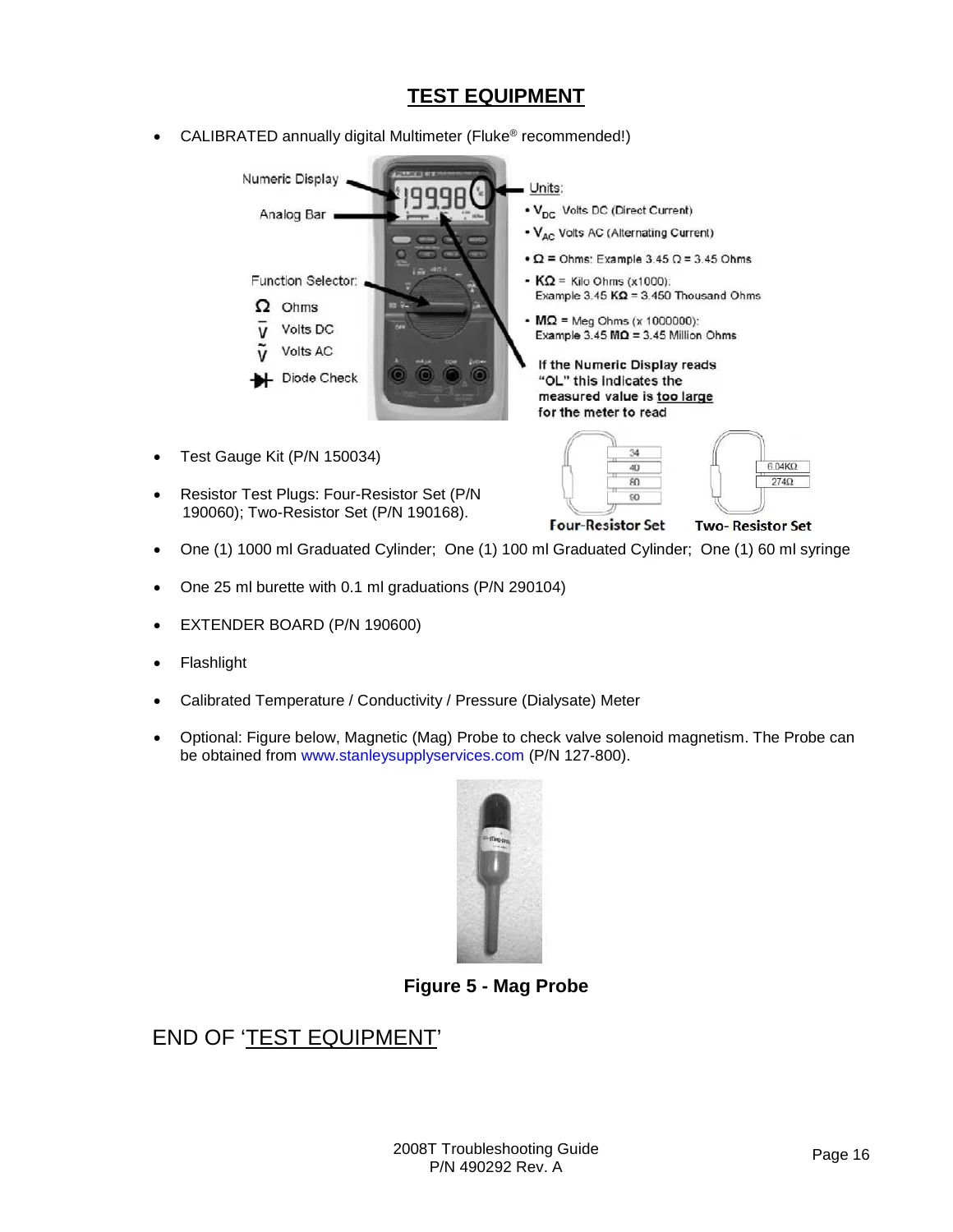
TEST EQUIPMENTp. 20
VOLTAGE DETECTOR CALIBRATIONp. 21
OPERATING MODESp. 23
Auto Flowp. 25
End of ‘How to Enter Dialysis Program’p. 25
+How to Enter a Cleaning / Disinfection Program:p. 25
SECTION 1 – FLOW ERRORS IN DIALYSIS PROGRAMp. 27
Yes [Temperature] window is red! See procedure number F- 2.0.13 (page 46).p. 50
d) Allow [Temperature] to stabilize to between 35.0 and 39.0 C AND Conductivity to between 13.0 and 14.5 mS.p. 50
e) Close the shunt door!p. 50
f) Call debug screen 0 and watch Valve #24’s ‘dot’ for up to three (3) minutes OR until if it turns blue. TWO (2) possible scenarios:p. 50
a) This procedure uses a psi gauge. ENSURE it reads 0 psi before installing it.p. 54
b) Return BOTH concentrate connectors to their RINSE ports!p. 54
c) Figure right, tee the gauge between the Flow Pump's OUTPUT nozzle and its WHITE tubing.p. 54
d) To prevent leaks and false readings, tie wrap both sides of the gauge tubing.p. 54
e) See procedure number F- 3.2.2 (page 50).p. 54
F- 3.2.2 ISOLATE FLOW PUMPp. 54
a) IMPORTANT! Place the machine in RINSE!p. 54
b) Watch for one (1) minute to ENSURE a “No Water” alarm NEVER occurs!p. 54
c) Call debug screen 0. If debug does not appear press ‘Esc’ then call screen 0.p. 54
d) Allow Valve #43’s ‘dot’ (Figure right) to turn blue then WHITE again! While white, does pressure CYCLE, about every three (3) seconds, to between 35 and 36 psi?p. 54
F- 9.0.4 INPUT FLOW PUMP FLOW LESS THAN 800 ML / ISOLATE V26 INPUT FLOWp. 109
Yes More than 800 ml! Good flow from Valve #24! See procedure number F- 9.0.43 (page 108).p. 111
No Less than 800 ml! See parts a THROUGH f below.p. 111
a) Per the Figure below, remove Valve #24’s INPUT tubing!p. 111
b) Direct it into the bucket.p. 111
c) Return to Calibrate Hydraulics → Flow Pressure.p. 111
d) Press ‘Enter’ THEN ENSURE the Flow Motor is rotating.p. 111
e) Measure from the tubing for one (1) minute.p. 111
f) Press ‘Enter’ to return to “Calibrate Hydraulics”.p. 111
g) More than 800 ml collected?p. 111
Yes More than 800 ml! A) Reconnect Valve #24’s tubing; B) NOTE ONLY VALVE #24 will be checked and proceed to page 210, TROUBLESHOOTING A VALVE.p. 112
F- 9.0.43 GOOD FLOW FROM VALVE #24p. 112
A restriction is indicated in the ‘from (red) Dialyzer line’.p. 112
a) ENSURE no tubing restrictions at the DiaSafe® filter.p. 112
b) Figure BELOW, open Dialysate Filter #73 housing and ENSURE the filter is clean!p. 112
c) Figure above touch Valve #25’s black solenoid. Is it warm?p. 112
Yes Solenoid warm! TWO possible bad components: 1) Bad Actuator-Test Board1; 2) Bad Valve #25. 1 To LOCATE the board refer to Figure 4A (page 10).p. 112
No Solenoid is not warm! NOTE ONLY VALVE #25 will be checked and proceed to page 210, TROUBLESHOOTING A VALVEp. 112
F- 9.0.5 GOOD FLOW PUMP PRESSURE / ISOLATE CFS CIRCUITp. 113
F- 9.0.6 ACFS = 0p. 114
F- 10.0.0 BAD ACFS SIGNALp. 115
F- 11.0.0 ACFS = BETWEEN 0 AND 3.0p. 116
F- 12.0.0 CALIBRATE/TROUBLESHOOT DIALYSATE PRESSUREp. 119
F- 14.0.0 ISOLATE 'OUT OF BYPASS' CIRCUITp. 124
1) IF (and ONLY if) MORE THAN 800 ml collected! Valve #24 is okay! See procedure number F- 14.0.4 (page 120).p. 124
2) IF LESS than 800 ml collected! Bad flow from Valve #24. Proceed to page 122, procedure number F- 14.0.6.p. 124
a) ENSURE no tubing restrictions at the DiaSafe® filter.p. 125
b) Per the Figure below, open Dialysate Filter #73’s housing and ENSURE the filter inside is clean!p. 125
c) Per the Figure below, touch Valve #25’s black solenoid. Is it warm?p. 125
Yes The solenoid is warm! TWO (2) possible bad components: 1) Bad Actuator-Test Board OR; 2) Bad Valve #25p. 125
No The solenoid is NOT warm! NOTE ONLY VALVE #25 will be checked and proceed to page 210, TROUBLESHOOTING A VALVEp. 125
F- 14.0.8 VALVE #26 OKAYp. 127
a) Remove the clamp from Valve #26!p. 127
b) Obtain a bucket!p. 127
c) Per the Figure below, remove the tubing from Valve #24’s INPUT and direct into the bucketp. 127
Yes More than 800 ml! See procedure number F- 14.0.81 (page 123).p. 127
F- 15.2.4 MORE THAN 130 ML PER MINUTE COLLECTEDp. 131
LEFT BLANK INTENTIONALLYp. 135
+F- 16.0.0 LESS THAN 150 ML COLLECTED / ISOLATE RESTRICTOR #48p. 136
SECTION 2 – “NO WATER” ALARMp. 156
+NW- 1.0.0 VALVE ERROR = 0p. 156
SECTION 3 – FLOW ERRORS IN A CLEANING / DISINFECTION PROGRAMp. 170
NOTE! If you placed the machine in RINSE because a Flow Error was occurring in Dialysis Program return to Dialysis Program and proceed to page 23, SECTION 1 – FLOW ERRORS IN DIALYSIS PROGRAMp. 170
These procedures troubleshoot Flow Errors that occur in Heat Disinfect, Rinse, etc. Alarm banners include “Flow Error”, “Flow Inlet Error” and “Flow Recirc Error 1”.p. 170
Yes Rotating CCW! See procedure number CLEAN- 1.2.5 (page 175).p. 179
No NOT rotating CCW! See parts a THROUGH c below:p. 179
a) ENSURE HEAT DISINFECT OR RINSE is running!p. 179
b) Turn the Heater Breaker Switch OFF!p. 179
c) NOTING ONLY the DEAERATION MOTOR will be checked proceed to page 141, TROUBLESHOOTING MOTORS.p. 179
CLEAN- 2.1.2 ISOLATE FLOAT SWITCH #5p. 192
CLEAN- 6.1.0 ‘AIR’ MOVING THROUGH VALVE #29p. 210
a) Turn the machine OFF and LEAVE IT OFF!p. 210
Yes Air moving through Valve #29! Valve #29 is bad (sticking open).p. 210
No Air IS NOT moving through Valve #29! The Actuator-Test Board is bad!p. 210
VE- 3.5.0 ISOLATE VALVE #43p. 221
VE- 5.0.0 VALVE ERROR AT BALANCING CHAMBER CYCLE 1p. 223
Valves #32, #33, #35, and #38 ‘dots’ REMAINING blue. One of these valve circuits is causing the problem and these procedures isolate between them!p. 223
Valves #31, #34, #36, and #37 ‘dots’ REMAINING blue. One of these valve circuits is causing the problem and these procedures isolate between them.p. 225
+TROUBLESHOOTING VALVE ERRORS IN CLEANING PROGRAMSp. 228
SECTION 4 – TEMPERATURE PROBLEMSp. 236
No Pin 7 is LESS THAN 4.0 volts! Proceed to page 286, procedure number T- 2.0.6.p. 287
1) IF MORE THAN 100.0 volts! The heater is on! See procedure number T- 2.0.4 (page 284).p. 288
2) IF LESS than 100.0 volts AC! Proceed to page 295, procedure number T- 2.6.0.p. 288
T- 2.0.4 HEATER ON (MORE THAN 100 VOLTS)p. 288
No Pin 7 is LESS THAN 4.0 volts! See procedure number T- 2.0.6 (page 286).p. 289
T- 2.0.6 PIN 7 LESS THAN 4.0 VOLTSp. 290
1) IF more than 100.0 volts AC! Return NTC #2’s connector to the 1st distribution board position from the left, “CON-NTC”. The new boards fixed the problem!p. 292
2) IF less than 100.0 volts AC! See procedure number T- 2.1.5 (page 288).p. 292
T- 2.1.5 HEATER VOLTAGE LESS THAN 10 VOLTS ACp. 292
No Pin 7 is 3.9 volts OR LESS! See (ABOVE) procedure number T- 2.0.6 (page 286).p. 293
T- 2.2.0 PIN 6 LESS THAN 9.5 VOLTS DC / ISOLATE POWER LOGIC BOARDp. 296
T- 2.2.1 LESS THAN 9.5 VOLTS AT PIN 6 / ISOLATE SENSOR BOARDp. 297
b) Turn the machine is OFF.p. 297
c) Swap in a known good Sensor Board*. * To LOCATE the board see Figure 4A (page 10).p. 297
T- 2.6.0 HEATER VOLTAGE LESS THAN 10.0 VOLTS / ISOLATE POWER SUPPLY COMPONENTSp. 299
T- 2.6.5 NO BURNING AT R10 AND R11 / ISOLATE HEATER SWITCHp. 301
T- 3.0.0 IN HEAT DISINFECT TEMPERATURE DID NOT REACH 80 Cp. 304
T- 4.0.0 TEMPERATURE EXCEEDS 39.0 C / ISOLATE TEMPERATURE CONTROLp. 310
T- 4.4.0 CHECK TEMP DISPLAY CALIBRATION (1)p. 315
+T- 4.5.0 ISOLATE TRIAC / POWER CONTROL BOARDp. 316
SECTION 5 – CONDUCTIVITY / ON LINE CLEARANCE PROBLEMSp. 339
1) IF (and ONLY if) the ACID PUMP continues to stroke BUT the BICARB PUMP stops: This is normal! See procedure number CO- 1.0.8.1 (page 359).p. 362
2) IF the BICARB PUMP is stroking AND the ACID PUMP stops: See parts a AND b below:p. 362
a) CAUTION! To prevent damage turn the machine OFF!p. 362
b) Figure above the acid (“Conc-P”) and bicarbonate pump (“Bic-P”) distribution board connectors are reversed!p. 362
Call the Home screen. What color is the [Conductivity] window (Figure right)? TWO (2) possible scenarios:p. 372
CO- 3.2.0 [CONDUCTIVITY] WINDOW = 10.0 mSp. 377
What color is the Home screen’s [Conductivity] window now? TWO (2) possible scenarios:p. 378
CO- 4.4.1 ISOLATE THE CONNECTORp. 382
CO- 5.0.0 UNSTABLE CONDUCTIVITY / ISOLATE PRESSURESp. 384
+CO- 9.0.0 BIC DOT IS WHITE / ISOLATE BICARB DEBUG SIGNALp. 413
SECTION 6 – CONCENTRATE PUMP ERRORSp. 445
The CONC (Acid) and Bic (Bicarbonate) pumps each have optical End Of Stroke (EOS) sensors that monitors the pump pistons when transported back and forth by their stepper motors. From debug screen 0, per the Figure below, if all systems are okay, the ‘…p. 445
EOS- 1.0.0 DETERMINE THE EOS ERRORp. 445
EOS- 2.0.0 ACID SYSTEM PROBLEM / ISOLATE THE ACID PUMPp. 446
EOS- 3.0.0 BICARBONATE (BIC) SYSTEM PROBLEM / ISOLATE THE BIC PUMPp. 447
+EOS- 4.0.0 PUMP SYMBOL REMAINS PINK / ISOLATE THE PUMP CIRCUITSp. 448
SECTION 7 – COND REF FAILURE OR COND OFFSET FAILUREp. 452
CR- 1.0.2 ISOLATE (-) 12 VOLT DC SUPPLYp. 453
b) Set your CALIBRATED volt meter to DC Voltage (VDC).p. 453
c) Connect the meter’s black lead to chassis ground (see Figure 2 (page 4)).p. 453
d) Turn the machine ON (Fan running)!p. 453
e) Measure at the EXTENDER BOARD’S -12V measuring point. Between -11.0 and -13.0 volts DC?p. 453
+CR- 1.0.9 ISOLATING NEGATIVE (-) TWELVE VOLTSp. 455
SECTION 8 – FILLING PROGRAM (AIR LEAK) PROBLEMSp. 456
Filling Programs NORMALLY occur when air is sensed by Chamber #69’s Air Sensor #6 i.e. Chamber #69’s text box says “Air”. They are indicated with a “Filling Program” or “10 Fill Pgm in 1 Hr” or “TMP Is Low” banner. Also, debug screen 1’s FILACT = 1.p. 456
+Yes ‘Bob’ moving! See procedure number FIL- 1.0.0 (page 453).p. 456
SECTION 9 – TMP PROBLEMSp. 487
A) If the drain tubing is transparent, look through its ENTIRE length for bio-growth restrictions.p. 487
B) Call the Home screen. [Venous Pressure] MUST BE between -10 and 10 mmHg!p. 487
C) The Treatment Clock (Figure right) MUST be off i.e. “Tx Paused”!p. 487
D) ENSURE [Dialysate Flow] has been on and set to at least 500 ml/min, for six (6) minutes.p. 487
E) If the Automated Tests are running (screen reads “Test:.…”) allow them to finish!p. 487
F) Remove the ‘dummy venous chamber’ from the Level Detector module till instructed!p. 487
G) Press the [Dialysate Flow] window!p. 487
H) Set [Dialysate Flow] to 500 ml/min and press ‘Enter’.p. 487
I) DO NOT reset alarms till instructed!p. 487
J) Is the external flow indicator’s ‘bob’ moving at least ¼ up the sight tube?p. 487
K) Call debug screen 0. WITHOUT LOOKING AWAY, watch Flow Error for two (2) minutes. If EVER = 1, even just once, indicates a masked Flow Error! TWO (2) scenarios:p. 487
P) Allow up to three (3) minutes for the Conductivity window to turn white i.e. no Cond alarms!p. 488
S) Call debug screen 0.p. 488
T) Figure right, allow Valve #24’s ‘dot’ to REMAIN blue BEFORE continuing to part U indicating no Temp, Cond or bibag alarms!p. 488
U) Is the flow indicator’s ‘bob’ moving at least ¼ way up in the sight tube now?p. 488
Figure right, TWO (2) possible scenarios:p. 491
1) IF (and ONLY if) NOT equipped with bibag Connector: See procedure number TMP- 1.0.4 (page 487).p. 491
2) IF equipped with a bibag Connector: Is a disposable bibag (pouch) attached? (Yes or No)?p. 491
c) Allow a “No Water” alarm to occur THEN, after one (1) minute, the deaeration motor stops.p. 493
d) Remove the Deaeration gauge and reattach the tubing!p. 493
e) Turn the water on and allow the “No Water” alarm to go away!p. 493
f) Remove the hydraulic compartment from the cabinet!p. 493
g) Return BOTH concentrate connectors to their rinse ports.p. 493
h) Place the machine into RINSE to pressurize the secondary hydraulic circuit! ENSURE a “No Water” alarm does NOT occur!p. 493
Figure 69 – Hydraulics Top View, Pumpsp. 495
c) Call debug screen 1. Is FILACT (middle column) = 1?p. 496
This procedure ENSURES Valve #43 is not sticking closed AND allows Conductivity to increase:p. 499
a) From the Home screen, press the [Dialysate Flow] window!p. 499
b) Set [Dialysate Flow] to 800 ml/min and press ‘Enter’!p. 499
c) Call debug screen 0. WITHOUT LOOKING AWAY, watch Flow Error for three (3) minutes. It should NEVER = 1! TWO (2) possible scenarios:p. 499
1) IF (and ONLY if) Flow Error EVER = 1 even if only once: Proceed to page 23, SECTION 1, FLOW ERRORS IN DIALYSIS PROGRAM.p. 499
2) IF Flow Error ALWAYS = 0! See parts a THROUGH e belowp. 499
a) From the Home screen, allow [Conductivity] to stabilize between 13.0 and 14.5 mS!p. 499
b) Call debug screen 1. Allow FILACT = 0 ALWAYS. NOTE! If FILACT DOES NOT = 0, after two (2) minutes, most likely the female Air Sensor connector IS NOT plugged in PROPERLY!p. 499
c) Open the shunt door and LEAVE IT OPEN till instructed!p. 499
d) Install a ‘dummy venous chamber’ in the Level Detector module!p. 499
e) TMP ALARM RESET SEQUENCE: i) Press and release the ‘Reset’ key then immediately press and hold it for three (3) seconds; ii) Allow thirty (30) seconds; iii) If ANY alarm occurs attempt RESET up to twice more BEFORE continuing to procedure number T…p. 499
From debug screen 10, based on PDIA (middle column). TWO (2) possible scenarios:p. 511
LEFT BLANK INTENTIONALLYp. 517
LEFT BLANK INTENTIONALLYp. 518
* To LOCATE Transducer #9 refer to Figure 6 (page 22).p. 519
LEFT BLANK INTENTIONALLYp. 519
+TMP- 9.0.0 VALVE #28 LEAKING / ISOLATE ACTUATOR-TEST BOARDp. 520
SECTION 10 – PRESSURE TESTS FAILINGp. 521
PHT- 1.0.0 “GET NEG TMP” LASTING FOREVER / ISOLATE UF PUMPp. 522
Check #1: Figure right, the ENTIRE length of the dialyzer lines ESPECIALLY the dialyzer quick connectors!p. 523
Check #2: The hydraulic compartment! Puddles on the compartment floor may indicate an active leak!p. 523
Check #3: Figure right, from the DiaSafe® filter housing and tubing connections!p. 523
Check #4: ENSURE the external flow indicator’s (sight tube) fittings are tight!p. 523
f) Allow two (2) minutes BEFORE continuing to part g.p. 530
g) Reset all alarms and repeat the Pressure Tests. Do they BOTH pass?p. 530
Yes Both Pass! The DiaSafe® filter MAY have been causing the problem HOWEVER, see procedure number PHT- 4.0.0 (page 527).p. 530
No Pressure test(s) Fail! Proceed to page 483, SECTION 9 – TMP PROBLEMSp. 530
A) Figure right, if the machine is equipped with a bibag Connector see part B. If NOT see procedure number PHT- 4.1.0 (page 527).p. 531
B) Is a disposable bibag (pouch) attached (Yes or No)?p. 531
f) Allow three (3) minutes BEFORE continuing to part g.p. 533
Yes On Line PHT Failed! See procedure number PHT- 4.7.0 (page 531).p. 535
+Automated Pressure Holding Test (PHT) Theory:p. 536
SECTION 11 – INDUCED AIR LEAK TESTSp. 538
The following procedures use negative dialysate pressure to locate a potential air leak. Use a flashlight to look THROUGH tubing. If air is seen continue, against the direction of flow (Figure below), to the next component until air bubbles are not se…p. 538
NOTE! Air is NORMAL in some locations, for example through the input tubing of Deaeration Pump #20 AND in the ‘To Drain’ circuit.p. 538
AIR- 1.0.0 ACHIEVE NEGATIVE DIALYSATE PRESSUREp. 538
Figure 76 – Hydraulics Top Viewp. 540
Figure below, ENSURING TMP is between 300 and 360 mmHg, for one (1) minute, watch through the INPUT tubing at the rear side of Chamber #69 (Location #10 (L10)). Air bubbles seen?p. 541
+AIR- 1.0.102 LEAK TEST HYDROCHAMBERp. 544
SECTION 12 – INDUCED POSITIVE PRESSURE TESTSp. 545
SECTION 13 – DEAERATION PROBLEMSp. 547
DAIR- 1.0.0 ISOLATE ACTUATOR-TEST BOARD CONTROLp. 547
DAIR- 4.0.0 ISOLATE VALVE #39p. 549
DAIR- 4.0.1 RECHECK VALVE #39p. 550
+DAIR- 6.0.0 ISOLATE THE DEAERATION MOTORp. 551
SECTION 14 – UF (ULTRAFILTRATION) PUMP PROBLEMSp. 552
THREE checks! Answer for all three at Check #3:p. 552
Check #1: Does the “UF Pump Alarm” banner appear?p. 552
Check #2: Call debug screen 0. Figure right, is the UF Pump ‘dot’ ALWAYS blue? (i.e. NEVER white)p. 552
Check #3: Figure right, is the UF Pump symbol PINK?p. 552
Figure 86 – UF Pump Adjustmentp. 554
UF- 2.1.0 UF PUMP CALIBRATES OKAY / ISOLATE UF CIRCUIT IN DIALYSISp. 554
Yes BOTH pressure Tests pass! Proceed to page 555, procedure number UF- 7.0.0.p. 555
No Proceed to page 483, SECTION 9- TMP PROBLEMS.p. 555
UF- 3.0.0 INADEQUATE UF PUMP OUTPUTp. 555
Check #1: Does the “UF Pump Alarm” banner appear?p. 557
Check #2: Call debug screen 0. Is the UF Pump symbol pink?p. 557
+Check #3: Is the UF Pump’s ‘dot’ ALWAYS blue? (i.e. NEVER white)p. 557
SECTION 15 – BLOOD LEAK PROBLEMSp. 560
BL- 1.0.5 BLOOD LEAK ALARM?p. 561
Is the Blood Leak alarm still present (Yes or No)?p. 561
BL- 1.0.6 BLOOD LEAK ALARM NOT PRESENT (CHECK FOR AIR)p. 561
1) IF (and ONLY if) air is seen! Proceed to page 559, procedure number BL- 3.0.0.p. 561
2) IF no air seen: Proceed to page 565, procedure number BL- 6.0.0.p. 561
Per the Figure right, using a flashlight, are air bubbles MOVING into the machine through the clear acid and / or bicarb Inlet Tubing?p. 563
Yes Air seen! A) If using a jugs ensure they are full AND the wands reach the bottom of the jugs; B) Check the acid and / or bicarb connector’s O-rings and plug; C) Check the pickup wand(s) tubing.p. 563
+No air seen! See procedure number BL- 3.0.1 (page 559).p. 563
SECTION 16 – CHECKING THE ACTUATOR BOARD CABLEp. 570
SECTION 17 – CHECKING THE SENSOR BOARD CABLEp. 573
SECTION 18A – DIAGNOSTIC VALVE LEAK TESTSp. 576
ANY external leak, however small, MAY be causing IOS failures and MUST be repaired!p. 577
a) Place the machine into RINSE PROGRAM.p. 577
b) Using a flashlight, THROUGHLY check for external leaks.p. 577
c) Check the ENTIRE length of the dialyzer lines for leaks (i.e. dialyzer quick connectors, external flow indicator, connections at the rear of the machine and (if equipped) the sample port.p. 577
d) Check the DiaSafe® filter tubing AND DiaSafe® housing for external leaks.p. 577
+e) If a leak is NOT located allow two (2) minutes then repeat parts a THROUGH d! If still NO LEAKS see procedure number AUTOTEST- 2.0.0 (page 573).p. 577
SECTION 18B – MANUAL BALANCING CHAMBER VALVE LEAK TESTSp. 582
B. Intensive work is done inside the distribution board, plugging and unplugging valves. Referring to Figure 95 (page 578), ensure that all balancing chamber valves (#31 through #38) have their distribution board connectors labeled correctly and are p…p. 582
+C. A leak is verified through the top balancing chamber valve OUTPUT nozzles (after the tubing is removed). Ignore small water crowns that may appear. If a valve is leaking it will continually drip.p. 582
SECTION 19 – TESTING FOR LEAKING BALANCING CHAMBER DIAPHRAGMp. 584
SECTION 20 – TROUBLESHOOTING OVERFLOW FROM THE VENT TUBINGp. 589
SECTION 21 – HYDRAULIC LEAKSp. 602
SECTION 22 – “WD: FAIL LONG PULSE” OR “WD: FAIL SHORT PULSE”p. 619
SECTION 23 – HEATER RELAY TEST FAILp. 625
SECTION 24 – “DIASAFE TEST FAILED”p. 633
A) If a DiaSafe® test is running allow it to finish BEFORE CONTINUING to part B. It is NORMAL for Flow Error = 1 WHILE a DiaSafe® test is runningp. 633
B) Using a flashlight, ENSURE no air bubbles are flowing into the machine through the Acid and Bicarbonate inlet tubing. If air is seen there is a problem with a concentrate connection.p. 633
C) From the Home screen, press the [Dialysate Flow] window.p. 633
E) ENSURE a “No Water” alarm NEVER occurs!p. 633
F) Call debug screen 0. WITHOUT LOOKING AWAY, watch Flow Error for two (2) minutes. If EVER = 1 indicates a Flow problem. TWO (2) possible scenarios below:p. 633
H) See procedure number DIASAFE- 2.0.0 (page 629).p. 633
+DIASAFE- 3.0.0 PRESSURE TESTS PASS / DIASAFE® TESTp. 634
SECTION 25 – TROUBLESHOOTING POWER DISTRIBUTIONp. 642
a) Per the Figure below, ENSURE the ribbon cable BETWEEN the Functional and UI-MICS board is plugged in securely i.e. P23 Functional board ↔ J6 UI-MICS board!p. 649
b) Turn the machine on (fan running).p. 649
c) Allow fifty (50) seconds! If (and ONLY if) the screen problem continues, proceed to page 646, procedure number P- E.0.0p. 649
P- E.0.0 PREPARE TO ISOLATE +12 AND +5 VOLT DC SUPPLIESp. 650
P- E.2.0 ISOLATE POWER LOGIC +12 AND +5 VOLT DCp. 650
P- F.4.0 BOTH +12 AND +5 VDC LOW / ISOLATE 24 VOLTS DC AT POWER LOGIC BOARDp. 657
P- F.5.0 ISOLATE +24V-Ap. 658
LEFT BLANK INTENTIONALLYp. 665
P- G.5.3 SYMPTOM STILL PRESENT / ISOLATE USB PORT #1p. 666
P- G.5.4 SYMPTOM REOCCURS / ISOLATE HYDRAULIC SENSORSp. 667
P- 1.0.5 POWER BUTTON OKAY / ISOLATE POWER LOGIC BOARDp. 694
P- 1.0.6 X2 / PIN 3 MORE THAN 6.0 VOLTS / ISOLATE POWER LOGIC BOARDp. 695
Figure right, is the fan running i.e. air felt from the fan vents?p. 695
No Fan is NOT running! Is the screen on OR is it remaining black (TWO (2) possible scenarios)?p. 695
1) IF (and ONLY if) the screen is on: The fan is bad!p. 695
2) IF the screen is remaining black: Unplug the machine and replace Main Relay K1* AND its four pin cable.p. 695
* To LOCATE K1 and its cable refer to Figure 132 (page 710).p. 695
.p. 695
P- 1.1.02 ISOLATE POWER LOGIC BOARD CABLE (PIN 4)p. 697
Figure 126 – Power Control Board Solder Sidep. 697
Figure 127 – Power Control Board / Fuses S12 and S16 / ST2 and ST1p. 698
P- 2.0.0 INITIALIZATION DOES NOT COMPLETE / ISOLATE PUMPSp. 701
P- 2.0.2 SYSTEM INITIALIZATION DOES BOT REACH 100% / ISOLATE +24 V-Ap. 703
LEFT BLANK INTENTIONALLYp. 707
P- 2.0.7 ISOLATE ‘WATCH DOG OUTPUT’p. 707
+P- 2.0.7 ISOLATE ‘WATCH DOG OUTPUT’p. 707
SECTION 26 – VALVE #1 OR VALVE #2 FAILp. 715
SECTION 27 – “ACT BLOOD PUMP FAILED”p. 724
SECTION 28 – HEAT EXCHANGER LEAKING EXTERNALLYp. 729
SECTION 29 – “BIBAG: VALVE 1 OR 2 ERROR”p. 731
SECTION 30 – “V104/V108 STUCK CLOSED” OR V104 ER C = 1p. 733
SECTION 31 – VALVE 104 OR VALVE 105 ERRORp. 748
SECTION 32 – “V105 STUCK CLOSED” OR V105 ER C = 1p. 750
SECTION 33 – “BIBAG: VENT TOO LONG”p. 758
APPENDIX A – TARGET DEAERATION PRESSURES PER GEOGRAPHICAL AREAp. 761
APPENDIX B – CALIBRATE IF REPLACED (non-bibag components)p. 762
APPENDIX C CALIBRATE IF REPLACED (bibag components)p. 763
APPENDIX D – BLOOD PUMP ERROR CODESp. 764

Reviews
There are no reviews yet.