
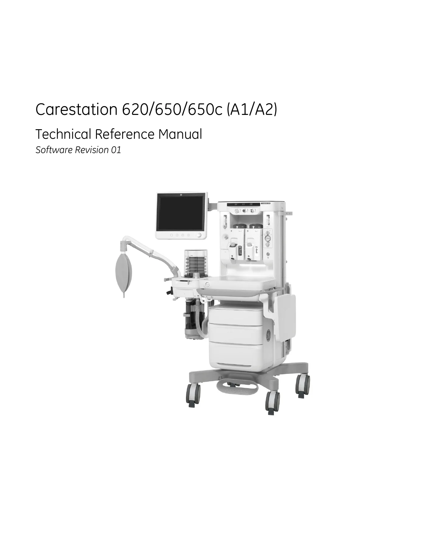
GE Carestation 620/650/650c (A1/A2) Technical Reference Manual – Anesthesia Machine Service PDF
Original price was: $39.95.$24.95Current price is: $24.95.
Complete GE Healthcare Carestation 620/650/650c (A1/A2) Technical Reference Manual for anesthesia machine service, calibration, troubleshooting, repair procedures, illustrated parts, schematics, and planned maintenance.
Description
GE Carestation 620/650/650c (A1/A2) Technical Reference Manual
This GE Carestation 620/650/650c (A1/A2) Technical Reference Manual is a detailed service document for the Carestation 620, Carestation 650, and Carestation 650c anesthesia systems in A1 and A2 configurations. It brings together theory of operation, checkout procedures, service menus, calibration steps, installation and functional checks, troubleshooting flowcharts, software download instructions, repair procedures, illustrated parts, schematics, PC service application guidance, and planned maintenance into one technical reference. The document is identified as 2076163-001 Rev P 11 2019 and shows Software Revision 01 on the cover.
File Details
- Manual type: Technical Reference Manual
- Brand: GE Healthcare
- Model series: Carestation 620/650/650c (A1/A2)
- Document number: 2076163-001
- Revision: Rev P
- Date shown: 11 2019
- Software revision shown: 01
- Language: English
- Page count: 522 pages
- File format: PDF
Chapters Covered
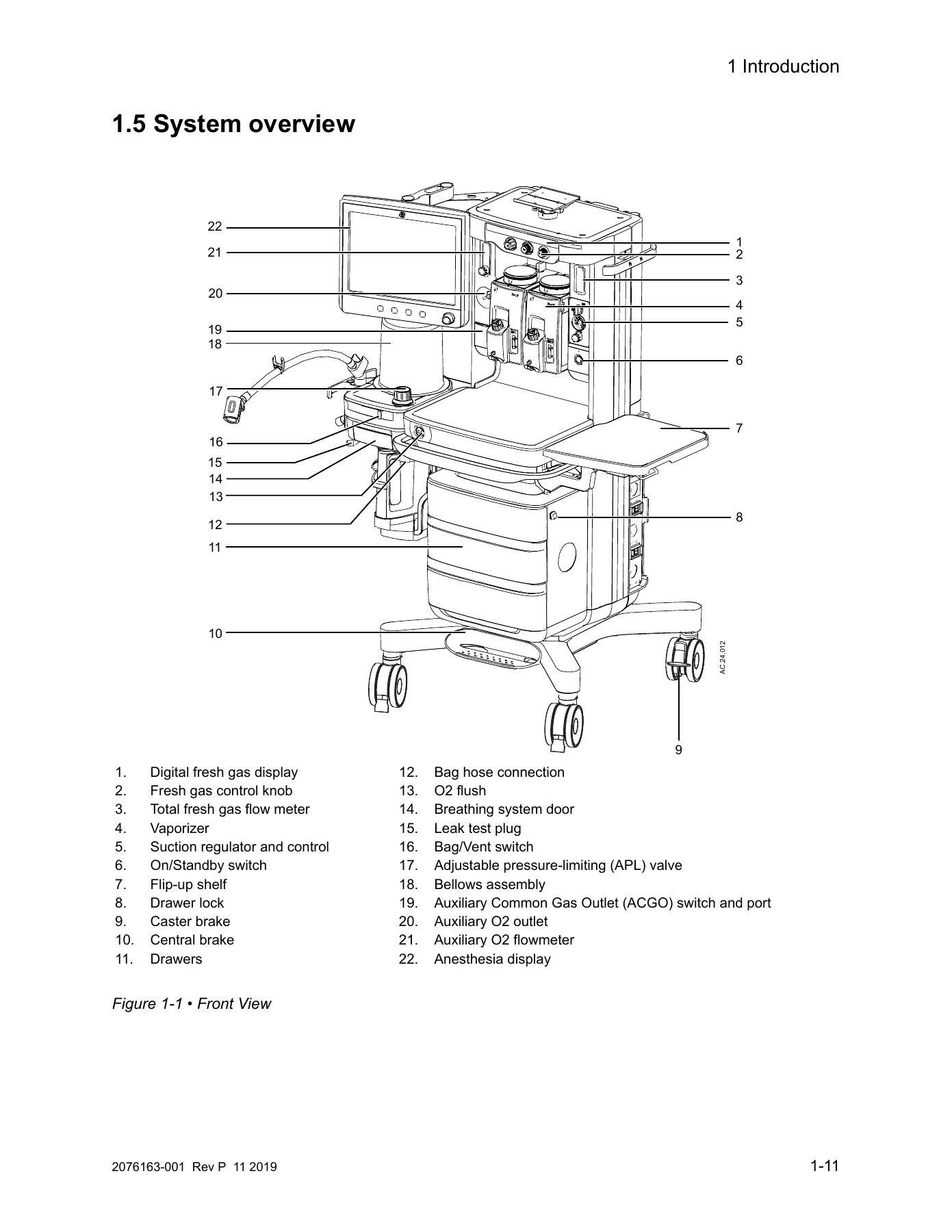
- 1 Introduction – general information, main machine model information, serial number information, UDI information, trademarks, manual scope, user reference manual, overview, system overview, feature overview, display control, anesthesia system display, display navigation, system information, symbols, and abbreviations.
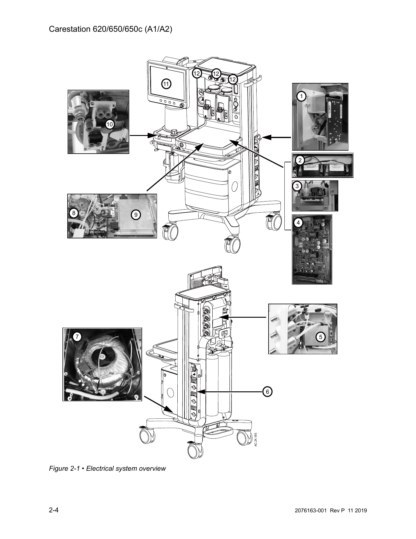
- 2 Theory of Operation – electrical system, power subsystem, AC-DC power supply, Power Management Board, battery, system communication, software POST, Display Unit, Anesthesia Control Board, Frame Interface Board, light and digital LED flow display boards, Sensor Interface Board, mixer solenoid valves, gas flow through the anesthesia machine, flow through the breathing system, ventilator, and ventilator mechanical subsystems.
- 3 Checkout Procedures – inspecting the system, verifying annunciators, system checkout overview, Full Test, test results, individual tests, low pressure leak tests, bellows drop test, pipeline and cylinder tests, flow sensing test, flow control test, flush flow test, vaporizer back pressure and interlock test, alarm tests, auxiliary O2 flowmeter tests, integrated suction regulator tests, power failure test, and electrical safety test.
- 4 Installation and Service Menus – menu structure, Super User settings, service menu, installation menu, configuration, units, leakage limits, factory defaults, options, key codes, installed options, options upgrade, copy configuration, configurable checklist, software and hardware information, service logs, calibrations, and display diagnostics.
- 5 Calibration – primary regulators, secondary regulators, flow control needle valves, Link system calibration, drive gas regulator adjustment, and ventilator calibrations including Manifold P Span, Inspiratory Flow Valve, Bleed Resistor, Paw Span, Paw and ACGO Span, Zero Gas Transducers, Mixer Flow Sensor Zero, and Zero ACGO or AGSS.
- 6 Installation and Functional Checks – installation checklist, free breathing valve maintenance, pressure limit circuit test, MOPV pressure relief valve test, ACGO pressure relief valve test, scavenger positive relief functional check, auxiliary O2 flowmeter tests, integrated suction regulator tests, battery capacity test, and secondary monitor installation.
- 7 Troubleshooting – troubleshooting guidelines, high pressure and low pressure leaks, Failed state, Startup Screen POST messages, display troubleshooting, breathing system leak test guide, system troubleshooting flowcharts, system malfunction and gas control failure flowchart table, technical alarms, SIB pneumatic sense tubing leak test, and flow sensor accuracy test.
- 8 Software Download – overview, main menu and system information, software download process, download complete, and software compatibility check.
- 9 Repair Procedures – safety information, circuit board replacement precautions, KEY and BID label, bleeding gas pressure, rear panels, tabletop, top shelf, power components, ACB, FIB, SIB, Vent Engine, pipeline inlet manifold, cylinder supply modules, O2 flush valve, breathing system components, bag arm, gas control components, vaporizer manifold, auxiliary O2 flowmeter, suction regulator, On/Standby switch, ACGO module, AGSS, task lights, casters, display unit, display arm, transformer, and Tec 7 filler cap or O-ring.
- 10 Illustrated Parts – service tools, software tools, test devices, adapters, lubricants and adhesives, touch-up paint, external components, tabletop, middle pan, Vent Engine assembly, top shelf, AC power cords, AC inlet and outlet components, drawers, display unit, light boards, auxiliary O2 assemblies, O2 flush, ACGO, vaporizer manifold, rear enclosure, pipeline fittings, cylinder supplies, breathing system, bag arm, AGSS, suction regulator, display arm, flip shelf, pendant, cables, tubing, Legris fittings, and vaporizer service parts.
- 11 Schematics and Diagrams – system pneumatic circuits, color coded system pneumatic circuits, electrical system block diagram, Anesthesia Control Board block diagram, Power Management Board block diagram, Sensor Interface Board block diagram, Frame Interface Board block diagram, cabling block diagram, and AC inlet module schematics.
- 12 Service Application – PC requirements, System Status startup screen, schematics, menu items, File menu, Tools menu, Power Diagnostics, Gas Delivery Subsystem, Vent Subsystem, Gas Monitor, Window menu, and Help menu.
- 13 Maintenance Procedures – planned maintenance, parts replacement intervals, planned maintenance checklist, visual inspection, breathing system inspection, ventilator checks, annunciator verification, power failure test, pipeline and cylinder tests, flow sensing, flow control, display diagnostics, ventilator tests, auxiliary O2 flowmeter tests, suction regulator tests, ACGO relief valve test, AGSS inspection, flush flow test, vaporizer back pressure and interlock test, airway module calibration, alarm tests, system checkout, electrical safety checks, and final machine checks.
Across these chapters, the Carestation 620/650/650c (A1/A2) Technical Reference Manual gives service personnel a structured path from system understanding to hands-on maintenance. The early theory chapters explain how the electrical, pneumatic, breathing, and ventilator subsystems interact. The checkout and calibration chapters then define how to verify performance and restore specified operation. Later chapters support fault isolation, board and assembly replacement, parts identification, and planned maintenance, with schematics and block diagrams to help trace circuits, gas paths, and communications.
What This Service PDF Supports
This manual is aimed at trained service personnel who need documented procedures for the Carestation 620, Carestation 650, and Carestation 650c anesthesia machines. It covers the Display Unit, integrated electronics, gas delivery components, breathing system components, frame components, optional auxiliary O2 flowmeter, optional ACGO, and optional suction regulator. It also documents the service menus, calibration routines, software download workflow, PC-based Service Application, and technical alarm information used during diagnosis and repair.
- Understanding system architecture, gas flow paths, breathing system flow, and ventilator mechanical subsystems.
- Running checkout procedures, Full Test, individual tests, leak tests, flow tests, alarm tests, and electrical safety checks.
- Performing ventilator calibrations, regulator adjustments, needle valve calibration, Link system calibration, and zeroing routines.
- Troubleshooting pressure leaks, startup messages, display issues, communication faults, gas control failures, flow sensor problems, and technical alarms.
- Replacing boards, power components, breathing system parts, gas control parts, ACGO components, AGSS components, display parts, casters, and other serviceable assemblies.
- Locating illustrated parts, tubing, fittings, harnesses, and service tools.
- Following planned maintenance intervals, inspection steps, and final machine checks.
Who This Manual Is For
The Carestation 620/650/650c (A1/A2) Technical Reference Manual is written for trained and authorized service personnel with experience in anesthesia device repair. It assumes access to proper tools, test equipment, and the latest revision of the manual. The procedures cover both routine service and more involved repair tasks, including board replacement precautions and required actions after installing replacement printed circuit boards. Because the document includes checkout, calibration, troubleshooting, repair, and maintenance content in one reference, it can support planned service visits as well as fault-driven service work.
Practical Coverage Beyond the Basics
Several sections go beyond general maintenance. The troubleshooting chapter includes flowcharts for display issues, inaccurate volume ventilation, no ventilation, high intrinsic PEEP, ACB faults, ACB to FIB communication, DU to ACB communication, FIB faults, LED issues, airway module issues, and system malfunction screens. The technical alarms table lists error log entries, alarm text, conditions, priority, source, enabling criteria, and actions. The repair chapter includes detailed removal and replacement sequences for major assemblies and notes where calibrations or checkout procedures must follow. The illustrated parts chapter supports parts identification across the breathing system, gas supplies, electrical components, display, suction, AGSS, and vaporizers. The schematics chapter provides pneumatic and electrical diagrams for tracing system operation.
Put This Carestation Service PDF to Work
IMAGES PREVIEW
With the GE Carestation 620/650/650c (A1/A2) Technical Reference Manual, a technician can move from system theory to checkout, calibration, troubleshooting, repair, and planned maintenance using one referenced source. Correct procedures and specifications matter on anesthesia equipment because gas delivery, ventilation, monitoring, and scavenging functions must work together predictably. This PDF is delivered as an instant download after purchase, with no physical shipment, and can be viewed on a computer or mobile device and printed for service reference.
Reviews
There are no reviews yet.