
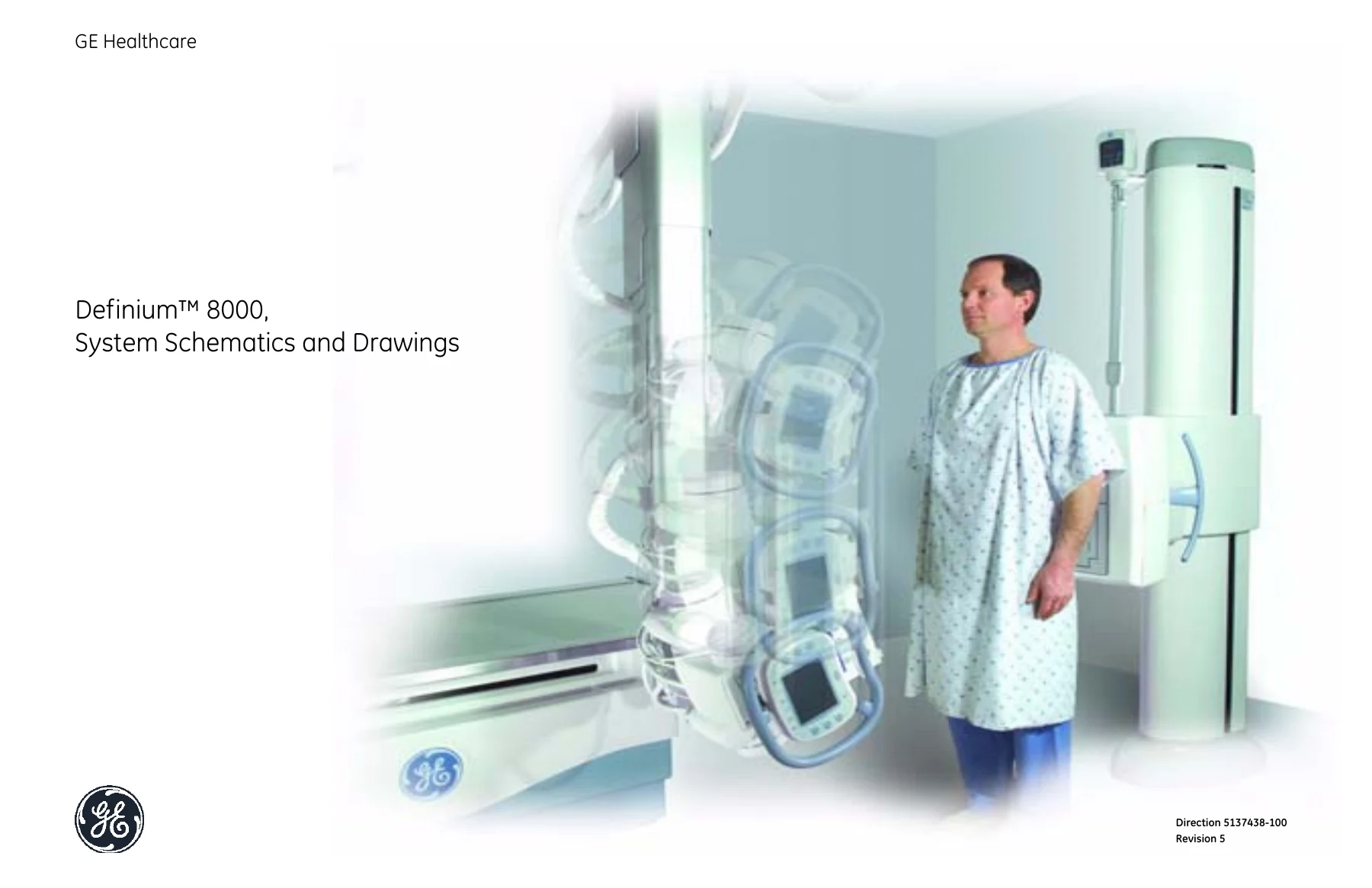
GE Healthcare Definium 8000 System Schematics and Drawings Manual – PDF Download
Original price was: $39.95.$24.95Current price is: $24.95.
Complete GE Healthcare Definium 8000 system schematics and drawings manual featuring block diagrams, CAN bus topology, board-level schematics for OTS, Table, Wall Stand and System Cabinet, plus full Master Interconnect Schematic (MIS) charts and grounding data.
Description
GE Healthcare Definium 8000 System Schematics and Drawings Manual
This GE Healthcare Definium 8000 System Schematics and Drawings Manual (Direction 5137438-100, Revision 5) is the complete schematic reference for the Definium 8000 radiographic system. It documents the electrical architecture of the OTS (Over-Head Tube Support), the patient Table, the Wall Stand, and the System Cabinet, together with the Master Interconnect Schematic (MIS) charts used for field installation and signal tracing. Every drawing is cross-referenced to its GE part number and board revision, so technicians can trace a signal from a bulkhead connector down to an individual IC, DIP switch, or jumper on a specific PWA.
File Details
- Manual type: System schematics and drawings service reference
- Brand / manufacturer: GE Healthcare (General Electric Company)
- Model: Definium 8000
- Document number: Direction 5137438-100
- Revision: 5 (Revision history through 24AUG2009, PCN 217574)
- Language: English
- File format: PDF
- Page count: 402 pages
Chapters Covered
- Chapter 1 — Introduction to Schematics (Content and Organization, Drawing Conventions, Rippers, Ports and Pages)
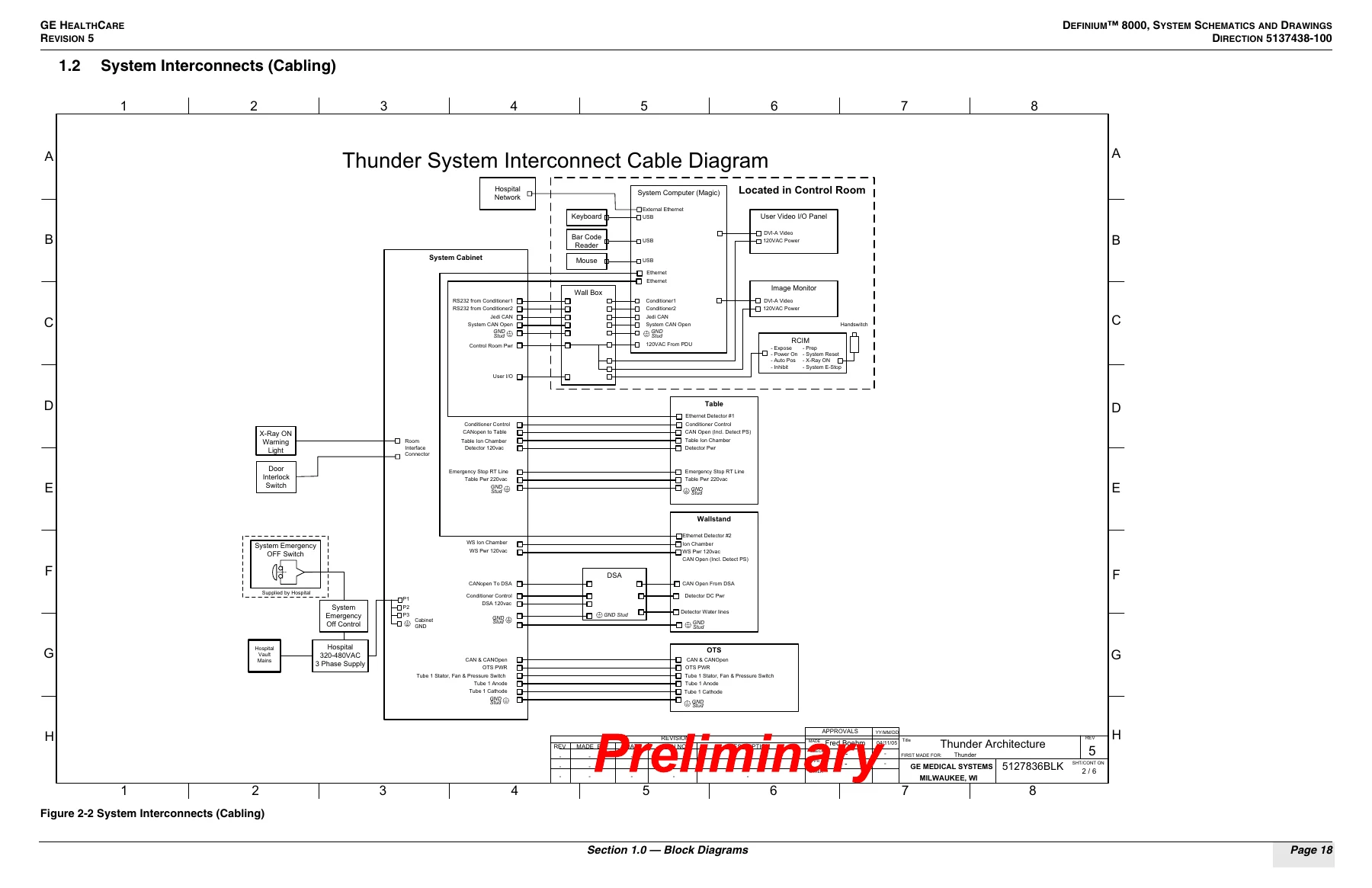
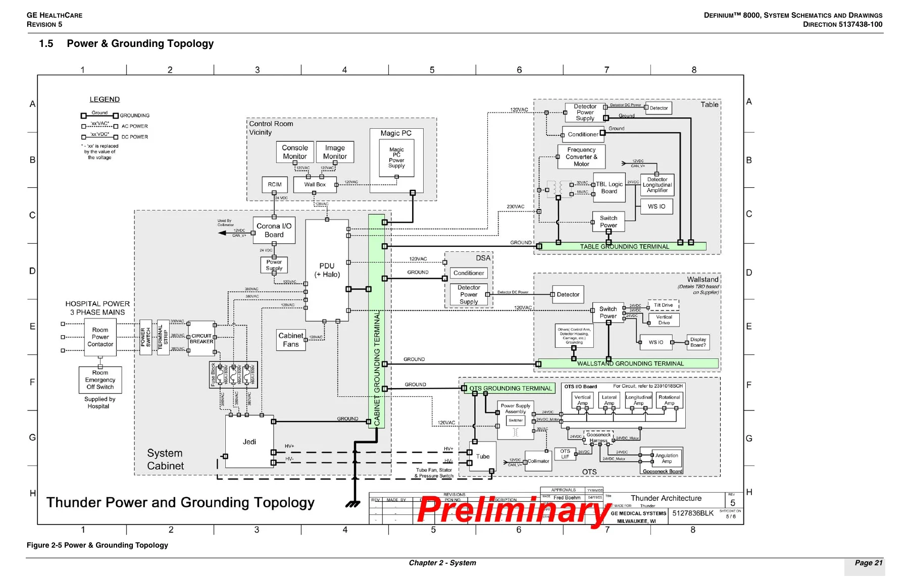
- Chapter 2 — System (Block Diagram, System Interconnects/Cabling, Serial Bus Communications Topology, Real Time Control Topology, Power & Grounding Topology, CAN Bus Topology for System/Wall Stand and Table/OTS, Jumpers, Switch Settings, and LEDs)
- Chapter 3 — Over-Head Tube Support (OTS Interconnect Diagram 5135678, Bulkhead Replacement Board 5117762, TSL Board 5135417, Gooseneck Board 2391155, User Interface Assembly 2383068, Power Supply Assembly 5138119)
- Chapter 4 — Table (Table Interconnect Diagram 5131070, Table I/O Board 5128333/2290188, Digital RAD Detector, DCB III Board, Table Interface Board 2336647, Table Logic Control Board 2336652, Motion Control Amplifier 2270267, Table Pedal Boards 2259298-25 and -24)
- Chapter 5 — Wall Stand (Wall Stand Interconnect, Bulkhead Connections and Signal Definition, Internal Cables 1 through 16, WSL Board 5135415, Bulkhead Replacement Board 5117762, Digital RAD Detector, DCB III Board)
- Chapter 6 — System Cabinet (5KV Power Distribution Unit 2293487, Halo Relay Board 2407245, Corona 2 Board 5138201, Jedi X-ray Generator 2374870 with Power Module, AEC Board, KV Control Board, Inverter Power Assembly, HV Tank, EMC/AC-DC Module and Auxiliary Module, System Cabinet Bulkhead 5134189)
- Chapter 7 — Master Interconnect Schematic (MIS) and Charts (Grounding and Wire Gauge Selection, Equal-Potential Grounding Rules, MIS Map Symbols, Power Distribution, Wire Gauge Guidelines, System MIS Map, and MIS Charts 11583A through 020072)
What this gives a technician is end-to-end electrical continuity of the entire Definium 8000. Block-level diagrams establish how the OTS, Table, Wall Stand, and System Cabinet connect; topology drawings show where each CAN node sits (with decimal node IDs called out); and the board-level schematics break those buses down to individual signals, connectors, and passive components. The switch and LED tables at the back of Chapter 2 let you confirm board health and DIP configuration before opening a schematic at all, while the MIS charts translate connector pinouts into the physical wire runs used during installation and site troubleshooting.
Board-Level Schematic Coverage in Detail
The OTS section includes the Tube Suspension Logic board with its power distribution, CAN interface and loopback wiring, amplifier headers, 24V-to-3.3V conversion stages, circuit breakers, and the fully protected MOSFET switch block for clutch and brake returns. The Gooseneck board section covers the angulation interface, load encoder receiver, CAN transceiver isolation, and its isolated 5V and CAN_VCC supplies. The Wall Stand Logic board schematics follow the same pattern for vertical and tilt drives, including the FPGA pinout, RS-422 to LVDS translation, and the CAN transceiver with its node-ID and baud-rate switch blocks. The Table drawings document the I/O board, logic control board, and motion control amplifier. The System Cabinet chapter is the deepest: the Corona 2 board is drawn across 40 sheets covering the Cyclone FPGA, DSP, CAN hub hardware, PDU relay control, E-stop conversion, and RCIM/Atlas RTB channels; the Jedi X-ray generator is documented from the generic interface board through the KV control board, inverter power assembly, HV tank, and EMC filter.
Practical Use and Audience
Field service engineers, biomedical equipment technicians, and installation teams use drawings like these to trace an intermittent CAN fault back to a specific loopback pin, to verify that a replacement board is set to the correct DIP configuration, or to confirm grounding and wire-gauge compliance during a room build. The Master Interconnect Schematic chapter supports that last task directly: it defines the equal-potential grounding rules, the maximum run lengths for each AWG size, and the voltage-regulation tables for 240 VAC and 120 VAC circuits at 1%, 3%, and 6% limits.
Because the material is organized by subsystem and then by assembly part number, the GE Healthcare Definium 8000 System Schematics and Drawings Manual works equally well as a desk reference for planned maintenance and as a bench document when a specific PWA is on the bench. The Chapter 2 LED tables, for example, describe heartbeat, safe-mode, CAN transmit, termination, and breaker-trip indicators for the Corona 2, WSL, OTS, Table Logic Control, and Detector Power Supply boards, so a technician can read board status before disconnecting anything.
What This Manual Enables
With this PDF on hand, a technician can follow a signal path through the entire Definium 8000 rather than guessing at connector pinouts or board revisions. Jobs that become practical include diagnosing CAN bus faults across the OTS, Table, Wall Stand, and System Cabinet; verifying DIP switch and jumper settings against the documented defaults; tracing power distribution from the 5KV PDU through the Halo relay board to each subsystem; checking grounding and wire gauge against the NEC-based MIS tables; and cross-referencing any schematic sheet to the exact GE part number and revision it documents. For a system of this complexity, correct procedures and correct part references are the difference between a clean repair and a repeat visit, and the manual supplies both.
IMAGES PREVIEW
Delivery is by instant PDF download after payment, with no shipping and no waiting. The file opens on any computer, tablet, or phone, and any page can be printed for use at the machine or on the bench.

Reviews
There are no reviews yet.