★ TRUSTED BY 321,897+ PROFESSIONALS WORLDWIDE
🏒
Trusted Business
Verified & Licensed
πŸ›‘οΈ
Virus Free Files
100% Safe Downloads
πŸ”’
Secure Payment
SSL Protected
⚑
Instant Delivery
Available Immediately
Sale!

GE HealthCare Giraffe Incubator Carestation CS1 Service Manual – 2077954-001 Rev T

Original price was: $44.95.Current price is: $25.95.

Complete 268-page GE HealthCare Giraffe Incubator Carestation CS1 Service Manual (2077954-001 Rev T, June 2024) covering calibration, troubleshooting, alarms, repair procedures, illustrated parts, and full specifications. Instant PDF download.

⚑
Instant PDF Download
Available immediately
πŸ’Ύ
Save to Your Device
Download & keep forever
πŸ›‘οΈ
Antivirus Scanned
100% virus-free
🌍
Trusted Worldwide
175,000+ customers

Description

GE HealthCare Giraffe Incubator Carestation CS1 Service Manual – 2077954-001 Rev T

This is the complete 268-page factory-format service manual for the GE HealthCare Giraffe Incubator Carestation CS1 (document 2077954-001, Revision T, dated June 2024). It is the manual biomedical engineers and hospital service technicians use to install, calibrate, troubleshoot, and repair this neonatal incubator down to component level.

File Details

  • Manual type: Full service/repair manual
  • Brand / Model: GE HealthCare Giraffe Incubator Carestation CS1
  • Document number: 2077954-001
  • Revision: T (June 2024)
  • Language: English
  • Page count: 268 pages
  • File format: PDF

Complete PDF Bookmark Tree

Complete Bookmarks

The complete bookmarks in the β€œGE HealthCare Giraffe Incubator Carestation CS1 Service Manual – 2077954-001 Rev T” are as follows:

Table of Contentsp. 5
List of Figuresp. 13
Service Language Disclaimerp. 17
Safety and Regulatory Informationp. 25
Warningsp. 25
Cautionsp. 32
Symbolsp. 34
Regulatoryp. 39
Standardsp. 39
User Responsibilityp. 39
About this Manualp. 41
Intended Audiencep. 41
Technical Competencep. 42
Conventionsp. 42
Chapter 1: Functional Descriptionp. 43
1.1 Control Boardp. 43
1.2 Relay Boardp. 45
1.3 Infant Care Single Board Computer (ICSBC)p. 46
1.4 Alarm Boardp. 46
1.5 Power Supplyp. 47
1.6 Peripheral Componentsp. 47
1.7 DataLinkp. 48
1.8 Servo Controlled Oxygen Optionp. 48
1.9 Humidifierp. 49
1.10 System Logsp. 50
1.11 Front Viewp. 51
1.12 Probe Panelp. 52
1.13 Side Viewp. 53
1.14 Rear Viewp. 54
1.15 Scales (Optional)p. 55
Chapter 2: Installation and Service Checkoutp. 57
2.1 Required tools and Personnel Protection Equipment (PPE)p. 57
2.2 Installationp. 57
2.3 Service Checkoutp. 58
2.3.1 Mechanical Checksp. 58
2.3.1.1 Power Cord Conditionp. 58
2.3.1.2 Partsp. 58
2.3.1.3 Wheel Operationp. 58
2.3.2 System Operationp. 59
2.3.2.1 Oxygen leak testsp. 60
2.3.2.2 Servo O2 performance testp. 61
2.3.3 Options Checksp. 62
2.3.4 Nurse Call Checksp. 62
2.3.5 Supply Valve Leak Testp. 62
2.4 Scale Installation and Service Checkout Proceduresp. 63
2.4.1 Installation Procedurep. 63
2.4.2 Scale Service Checkoutp. 64
2.4.2.1 Visual Inspectionp. 65
2.4.2.2 Center Weight Checkp. 65
2.4.2.3 Off Center Weight Checkp. 65
2.4.2.4 Load Cell Checkp. 66
Chapter 3: Calibration and Maintenancep. 67
3.1 Service Maintenance Schedulep. 67
3.2 Special Toolsp. 69
3.3 System Calibrationp. 69
3.4 Humidifier Calibrationp. 70
3.5 Servo Controlled Oxygen Calibrationp. 71
3.6 Scale Calibrationp. 71
3.7 Electrical Safety Testsp. 75
3.7.1 Groundp. 76
3.7.2 Earth Leakage and Chassis Leakage Currentp. 76
3.7.3 Leakage Currentp. 76
3.8 Line Voltage Calibrationp. 77
Chapter 4: Understanding the Service Interfacep. 79
4.1 Powering the Devicep. 79
4.2 Accessing Service Modep. 79
4.2.1 Change Passwordp. 80
4.2.2 Forgotten Passwordsp. 80
4.3 Understanding the Service Interface Layoutp. 81
4.4 Static Featuresp. 82
4.4.1 Pedalsp. 82
4.4.2 General Informationp. 83
4.5 Setupp. 83
4.6 Calibrationp. 85
4.7 Set Timep. 85
4.8 Upgradep. 86
Chapter 5: Troubleshootingp. 87
5.1 Troubleshooting Symptomsp. 87
5.2 Additional Troubleshooting Tipsp. 95
5.2.1 Raising and Lowering the Elevating Basep. 95
5.2.2 Incubator Heaters and Bed Safety Thermostatp. 95
5.2.3 Power Suppliesp. 96
5.2.4 Troubleshooting Harness Cables 6600-0701-700 and 2075837-001p. 97
5.3 Switches/Thermostatp. 97
5.3.1 Humidifier Heater/Safety Thermostatp. 98
5.3.2 Compartment Air Probe and Skin Temperature Probesp. 98
5.3.3 Heat Sink Sensor Thermistorp. 98
5.3.4 Elevating Base Motorp. 99
5.3.5 Troubleshooting the 50 Pin Ribbon Cablep. 99
5.3.6 Troubleshooting the Toroidal Transformerp. 99
5.4 Servo Controlled Oxygenp. 100
5.4.1 Statusp. 100
5.4.2 Components Controlp. 101
5.4.3 Servo Controlled Oxygen Alarm Messagesp. 102
5.4.4 Servo Controlled Oxygen Troubleshooting Tipsp. 106
5.4.4.1 Check Supply Valves and End Cap Safety Valvep. 106
5.4.4.2 Check Calibration Valve/Calibration Fanp. 106
5.4.4.3 Check Cooling Fanp. 106
5.4.4.4 Sensor Housing Temperature Sensor Temperature to Resistance Curvep. 107
5.5 Statusp. 107
5.6 Switchesp. 108
5.7 Errorp. 109
5.8 Alarm Testp. 110
5.9 Diagnostic Readingsp. 110
5.9.1 Statusp. 110
5.9.2 DAC Voltage Testp. 112
5.10 Scale Checksp. 112
5.10.1 Hardware Checkp. 112
5.10.2 Weight Checkp. 112
Chapter 6: Alarms and System Failure Codesp. 113
6.1 Alarmsp. 113
6.1.1 Compartment Sensor Failure Alarmp. 113
6.1.2 Patient Probe 1 Failure or Patient Probe 2 Failure Alarmp. 113
6.1.3 Patient Hot – Check Probe 1p. 114
6.1.4 Patient Cold – Check Probe 1p. 114
6.1.5 Bed Height Pedals Disabledp. 114
6.1.6 Bed Raise Pedal Pressedp. 115
6.1.7 Bed Lower Pedal Pressedp. 115
6.1.8 Bed Heater Failure Alarmp. 116
6.1.9 Bed Raise/Lower Pedal Failure Alarmp. 117
6.1.10 Fan Always in High Speed Alarmp. 117
6.1.11 Fan Failure Alarmp. 118
6.1.12 Humidity Failure Alarmp. 119
6.1.13 Motor Drive Failure Alarmp. 119
6.1.14 Power Failure (LED Indicator)p. 120
6.1.15 Temperature Out of Calibration Alarmp. 120
6.1.16 Up Pedal Pressed Alarmp. 120
6.1.17 Replace Clock Batteryp. 120
6.2 System Failure Codesp. 121
6.2.1 System Failure 0p. 121
6.2.2 System Failure 1p. 121
6.2.3 System Failure 2p. 122
6.2.4 System Failure 3p. 122
6.2.5 System Failure 5p. 123
6.2.6 System Failure 6p. 123
6.2.7 System Failure 7p. 123
6.2.8 System Failure 8p. 123
6.2.9 System Failure 11p. 124
6.2.10 System Failure 12p. 124
6.2.11 System Failure 13p. 124
6.2.12 System Failure 14p. 124
6.2.13 System Failure 15p. 124
6.2.14 System Failure 16p. 126
6.2.15 System Failure 18p. 127
6.2.16 System Failure 19p. 127
6.2.17 System Failure 20p. 127
6.2.18 System Failure 22p. 128
6.2.19 System Failure 23p. 128
6.2.20 System Failure 25p. 128
6.2.21 System Failure 26p. 129
6.2.22 System Failure 27p. 130
6.2.23 System Failure 28p. 130
6.2.24 System Failure 29p. 130
6.2.25 System Failure 30p. 131
6.2.26 System Failure 33p. 131
6.2.27 System Failure 34p. 131
6.2.28 System Failure 35p. 132
6.2.29 System Failure 36p. 132
6.2.30 System Failure 38p. 132
6.2.31 System Failure 55p. 133
6.2.32 System Failure 60p. 133
6.2.33 System Failure 61p. 133
6.2.34 System Failure 62p. 133
6.2.35 System Failure 63p. 133
6.2.36 System Failure 70p. 134
6.2.37 System Failure 71p. 134
6.2.38 System Failure 81p. 134
6.2.39 System Failure 82p. 134
6.2.40 System Failure 83p. 134
6.2.41 System Failure 85p. 135
6.2.42 System Failure 98p. 136
6.2.43 System Failure 99p. 136
Chapter 7: Repair Proceduresp. 137
7.1 Hood Removal for Replacementp. 137
7.2 Porthole Door Replacementp. 138
7.3 Display Head Removalp. 138
7.3.1 Rear Coverp. 138
7.3.2 Display Headp. 138
7.4 Right Rail Assembly Repair Proceduresp. 139
7.4.0.1 Removing the Old Harness from the Cable Carrier Channelp. 139
7.5 Uprights and End Capsp. 140
7.5.1 Re-installing the Uprightp. 141
7.6 Compartment Sensor Repairsp. 141
7.7 Lower Device Repairsp. 142
7.7.1 Removing the Chassis Cover with the Storage Drawer in Placep. 142
7.7.2 Incubator Fan, Fan Motor, and Optical Fan Sensorp. 143
7.7.3 Incubator Heater Replacementp. 144
7.7.3.1 Removing the Incubator Heater Closest to the Humidifier End of the Bedp. 144
7.7.3.2 Removing the Incubator Heater Closest to the Control Panel End of the Bedp. 144
7.7.4 Elevating Basep. 145
7.7.5 Chassis Replacementp. 147
7.7.6 Bed Raise/Lower Pedal Switchp. 148
7.8 Bed Tilt Brake Pad Replacementp. 148
7.9 Wheel Replacementp. 149
7.10 Humidifier Assembly Repairsp. 149
7.10.1 Disassemblyp. 149
7.10.2 Reassemblyp. 152
7.11 Control Panel and Display Module Proceduresp. 153
7.11.1 Probe Panelp. 153
7.11.1.1 Power Fail Batteryp. 154
7.11.2 Control Panel Componentsp. 154
7.12 Control Boardp. 154
7.13 Relay Boardp. 155
7.14 Solid State Relaysp. 155
7.15 Power Supplyp. 155
7.15.1 Toroidal Transformerp. 156
7.15.2 ISO Transformer, Circuit Breakers, Power Switches, and Power Outletsp. 156
7.16 Servo Controlled Oxygen Service Proceduresp. 157
7.16.1 Installing Oxygen Sensorsp. 157
7.16.2 Replacing the Vent Screenp. 157
7.16.3 Sensor Housing Repairsp. 158
7.16.3.1 Sensor Housing Repairs: Boards, Calibration Fan Assembly, and Sensor Plug Assemblyp. 158
7.16.3.2 Sensor Housing Repairs: Calibration Valve and Manifold Assemblyp. 159
7.16.4 Valve Housing Repairsp. 161
7.16.4.1 Valve Housing Repairs: Regulator Assemblyp. 162
7.16.4.2 Valve Housing Repairs: Supply Valvesp. 162
7.16.5 Servo Oxygen Board Repairsp. 162
7.17 Display Module Repairsp. 163
7.17.1 Rear Coverp. 163
7.17.1.1 Carrier Plate Hardwarep. 163
7.17.2 Alarm Lensp. 164
7.17.3 Alarm Boardp. 164
7.17.4 LCD Display Assemblyp. 166
7.17.4.1 LCD Display Disassemblyp. 166
7.17.4.2 LCD Display Assemblyp. 168
7.17.5 SBC (Single Board Computer) PCAp. 168
7.17.5.1 SBC Disassemblyp. 168
7.17.5.2 SBC Assemblyp. 171
7.18 Clock Battery Replacementp. 171
7.19 Display Harness Connectionsp. 172
7.20 Scale Repairp. 173
7.20.1 Scale Control Board Replacementp. 173
7.20.2 Load Cell Replacementp. 175
Chapter 8: Illustrated Partsp. 179
8.1 Probe Housingp. 179
8.2 Display Modulep. 181
8.3 Electrical Enclosurep. 183
8.4 Electronic Enclosure Ground Stackupp. 186
8.5 Harnessesp. 187
8.5.1 Relay Board Harness Connectionsp. 187
8.5.2 Control Board Harness Connectionsp. 188
8.6 Humidifier Transformer and RS-232p. 188
8.7 Bed and Side Panelsp. 190
8.8 Chassisp. 196
8.9 Humidifierp. 200
8.10 Elevating Basep. 202
8.11 Hood Latch, Wire Covers, and Uprightsp. 204
8.12 Hood and Compartment Sensorp. 206
8.13 Servo Control Oxygenp. 208
8.14 Storage Drawerp. 215
8.15 Optionsp. 216
8.16 Scale Part Numbers Listp. 224
8.17 Giraffe Scale Service Partsp. 225
8.18 Options PNsp. 226
8.19 Labelsp. 229
8.19.1 Label Illustrationsp. 229
8.19.1.1 Warning Label Setp. 230
8.19.1.2 Connector Panelp. 230
8.19.2 Raise/Lower Pedalp. 231
8.19.3 Rating Labelp. 231
8.19.4 Porthole Warningp. 231
8.19.5 Chassis Vent Servo O2p. 232
8.19.5.1 Servo O2 Maximum Pressure Labelsp. 232
8.19.5.2 Weight Limit Warningsp. 233
8.19.5.3 Port Coverp. 234
8.19.5.4 Branding Labelp. 234
8.19.6 Other Warningsp. 234
8.20 PCB Layoutsp. 235
8.21 Wiring Diagramsp. 238
Appendix A: Compartment and Skin Probe Characteristicsp. 245
Appendix B: Specificationsp. 247
Appendix C: RS-232 Serial Datap. 251
C.1 RS-232 Datalinkp. 251
C.2 Serial Data Interfacep. 252
C.3 Specificationsp. 252
C.3.1 Detailed description of data stream for Giraffe productsp. 252
C.3.2 Data streamp. 257
C.3.3 Alarm prioritiesp. 258
C.3.3.1 Understanding the Control panel displayp. 258
C.3.3.2 Understanding audio tonesp. 259
C.3.4 Alarm codesp. 259
C.4 Required characteristics of systems for support of Incubator RS-232 Datalinkp. 260
C.5 Nurse Call Interfacep. 261
C.6 Cable requirements for Datalink (Serial Comm and Nurse Call)p. 261
C.6.1 RS-232 pin definitionsp. 261
C.6.2 Nurse Call pin definitionsp. 262
C.6.3 Nurse Call signalsp. 262
C.7 Serial Data Interface cable connection requirementsp. 262
C.7.1 Cable requirementsp. 262
Indexp. 263

Chapters Covered

  • Safety and Regulatory Information – warnings, cautions, symbols, regulatory notes
  • Chapter 1: Functional Description – Control Board, Relay Board, Infant Care Single Board Computer (ICSBC), Alarm Board, Power Supply, DataLink, Servo Controlled Oxygen Option, Humidifier, System Logs, Front/Side/Rear views, optional Scales
  • Chapter 2: Installation and Service Checkout – required tools/PPE, installation, mechanical checks, system operation, oxygen leak tests, servo O2 performance test, options checks, nurse call checks, supply valve leak test, scale installation and service checkout
  • Chapter 3: Calibration and Maintenance – service maintenance schedule, special tools, system calibration, humidifier calibration, servo controlled oxygen calibration, scale calibration, electrical safety tests, line voltage calibration
  • Chapter 4: Understanding the Service Interface – powering the device, accessing service mode, password change/recovery, static features, setup, calibration, set time, upgrade
  • Chapter 5: Troubleshooting – troubleshooting symptoms, elevating base, incubator heaters and bed safety thermostat, power supplies, harness cable troubleshooting, switches/thermostats, servo controlled oxygen troubleshooting, diagnostic readings, scale checks
  • Chapter 6: Alarms and System Failure Codes – all patient and system alarms plus System Failure codes 0 through 99
  • Chapter 7: Repair Procedures – hood removal, porthole door, display head, right rail assembly, uprights and end caps, compartment sensor, lower device repairs, incubator fan/heater replacement, elevating base, chassis replacement, bed tilt brake pad, wheel replacement, humidifier assembly, control panel and display module, control board, relay board, solid state relays, power supply, servo controlled oxygen service procedures, display module repairs, LCD display assembly, SBC PCA, clock battery, display harness connections, scale repair
  • Chapter 8: Illustrated Parts – probe housing, display module, electrical enclosure, harnesses, humidifier transformer and RS-232, bed and side panels, chassis, humidifier, elevating base, hood latch/wire covers/uprights, hood and compartment sensor, servo control oxygen, storage drawer, options, scale part numbers, labels, PCB layouts, wiring diagrams
  • Appendix A: Compartment and Skin Probe Characteristics
  • Appendix B: Specifications – power requirements, operating and storage environment, system performance, weight scale performance, servo oxygen, humidity, mechanical dimensions and weight
  • Appendix C: RS-232 Serial Data – datalink and serial data interface specifications, alarm codes and priorities

Taken together, this GE HealthCare Giraffe Incubator Carestation CS1 Service Manual gives a technician everything needed to run a full service checkout, calibrate the humidifier, servo oxygen system, and scale, chase down a troubleshooting symptom to its root cause, cross-reference an alarm or System Failure code, and carry out a component-level repair using the illustrated parts and wiring diagrams.

What This Giraffe Incubator Carestation CS1 Manual Covers

The Giraffe Incubator Carestation CS1 troubleshooting chapter walks through symptom-based fault finding for the elevating base, incubator heaters and bed safety thermostat, power supplies, and the specific harness cables (6600-0701-700 and 2075837-001) known to cause intermittent faults. The Alarms and System Failure Codes chapter documents every patient alarm – from Compartment Sensor Failure through Bed Heater Failure and Motor Drive Failure – alongside the full System Failure 0-99 reference, so a tech can go from a code on the display straight to the corrective action.

Repair coverage in this GE Giraffe Carestation CS1 service manual is genuinely component level: hood and porthole door replacement, display head and rear cover removal, right rail assembly and upright/end cap work, compartment sensor repairs, chassis cover and elevating base service, incubator heater and fan motor replacement, humidifier assembly disassembly and reassembly, control panel and display module procedures (control board, relay board, solid state relays, power supply, toroidal transformer, ISO transformer), servo controlled oxygen sensor housing and valve housing repairs, LCD display and SBC (Single Board Computer) PCA replacement, and scale control board and load cell replacement.

IMAGES PREVIEW

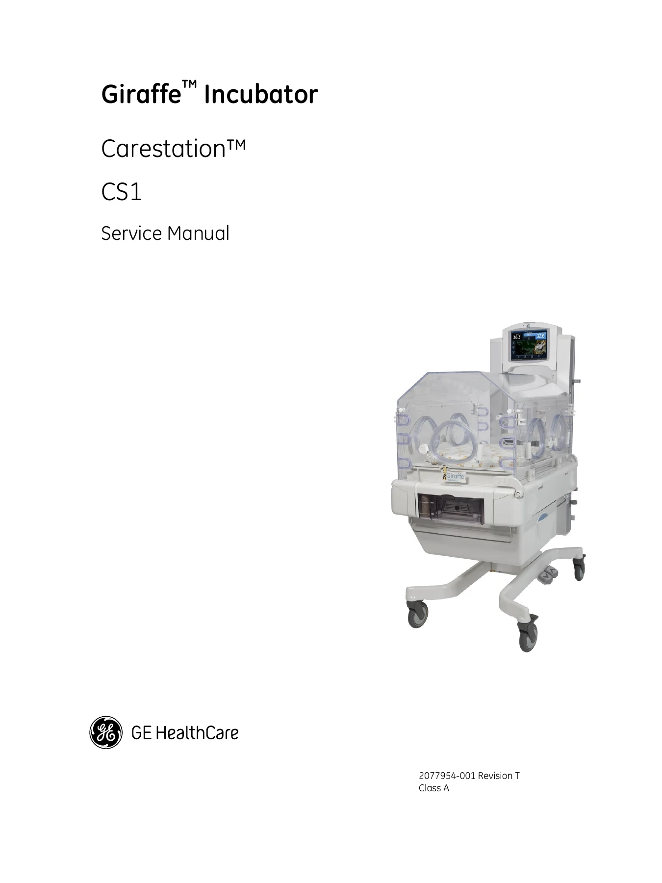
GE HealthCare Giraffe Incubator Carestation CS1 Service Manual - 2077954-001 Rev T β€” PDF page 1 preview
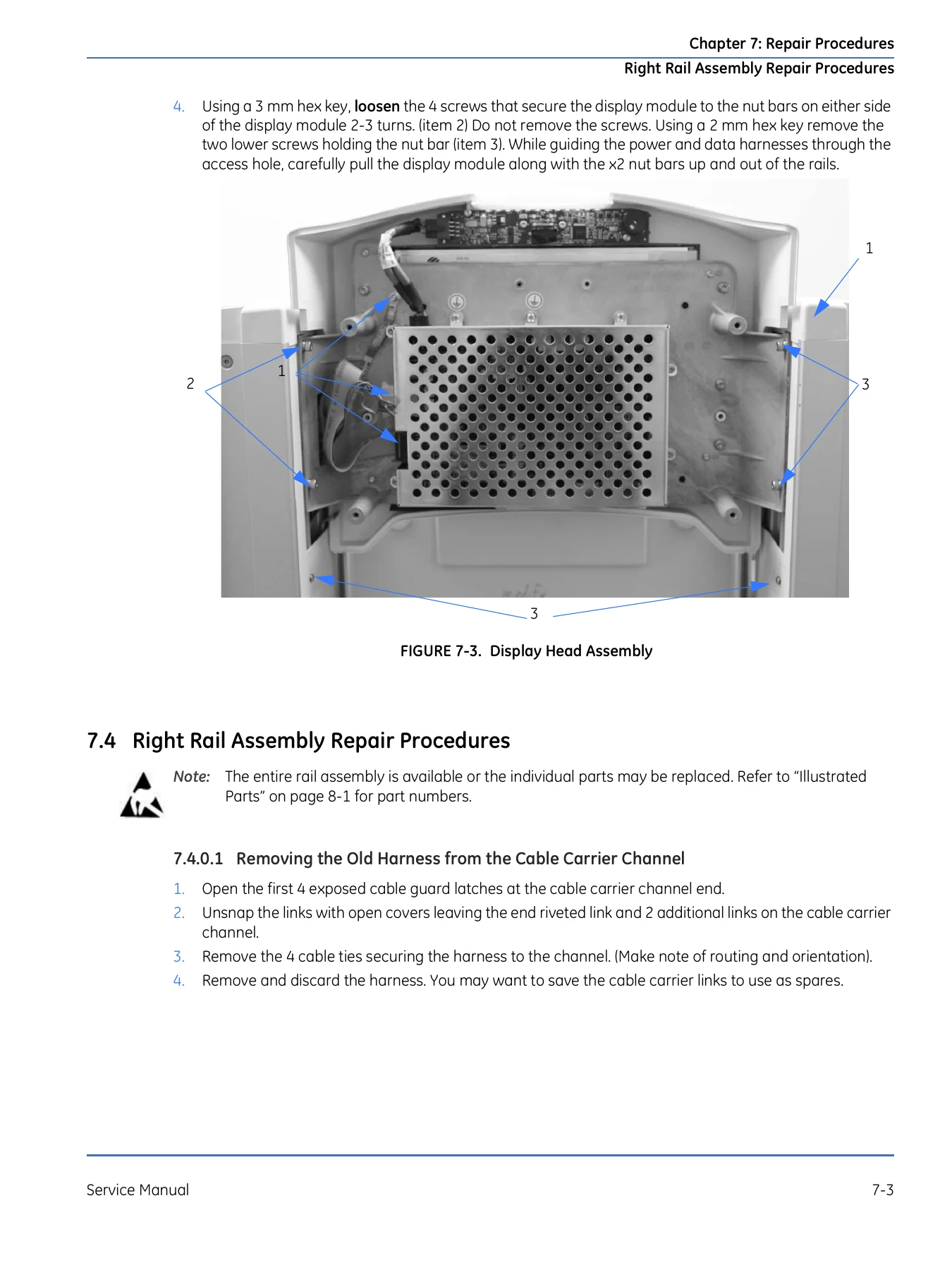
GE HealthCare Giraffe Incubator Carestation CS1 Service Manual - 2077954-001 Rev T β€” PDF page 139 preview
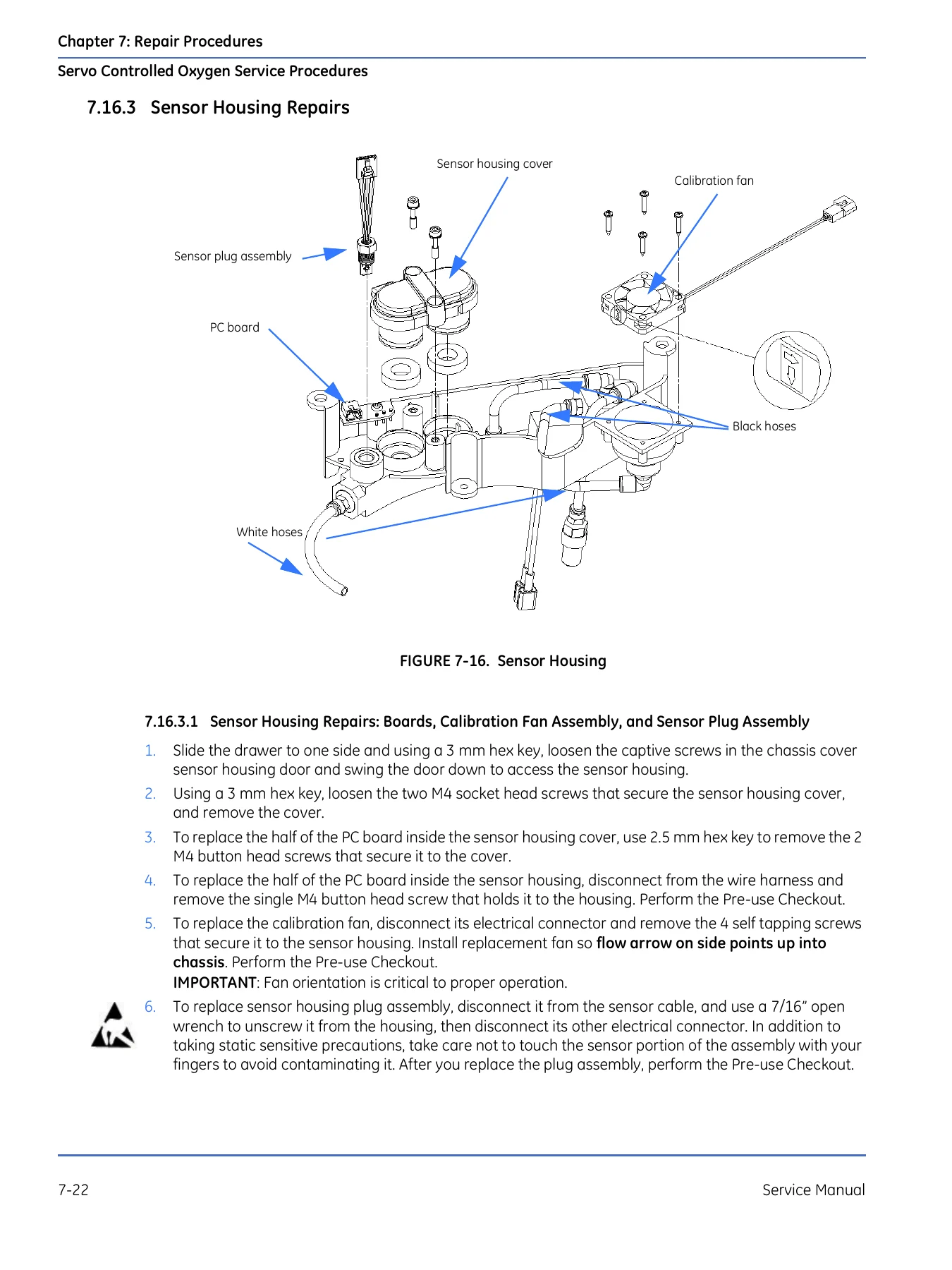
GE HealthCare Giraffe Incubator Carestation CS1 Service Manual - 2077954-001 Rev T β€” PDF page 158 preview

The Illustrated Parts chapter that follows gives exploded-view diagrams and part callouts for the probe housing, display module, electrical enclosure, harnesses, bed and side panels, chassis, humidifier, elevating base, hood and compartment sensor, servo control oxygen assembly, storage drawer, options, labels, PCB layouts, and full wiring diagrams – the reference a shop needs when ordering the correct FRU for a Giraffe Incubator Carestation CS1.

Specifications and Calibration Data

Appendix B lays out the complete specifications for the Carestation CS1: power requirements across 100V-240V mains, operating temperature and humidity ranges, patient temperature measurement and control accuracy, warm-up time, sound levels, weight scale performance (300g-8kg functional range, Β±10g accuracy), servo oxygen control range (21%-65%) and accuracy, humidifier ramp-up time and operating time without refill, and full mechanical dimensions and weight. Appendix C documents the RS-232 datalink output string field by field, together with the complete alarm code and priority tables, which is essential when integrating the incubator with a nurse call or remote monitoring system.

This level of factory-sourced calibration and specification detail is exactly what separates this Giraffe Incubator Carestation CS1 Service Manual from generic troubleshooting notes, and it is why hospital biomed departments and independent service organizations rely on the original documentation rather than guesswork.

Get Your Copy Instantly

With this GE HealthCare Giraffe Incubator Carestation CS1 Service Manual (2077954-001 Rev T) you can perform correct calibration and service checkout procedures, chase alarms and System Failure codes to a real fix, and complete component-level repairs using the correct FRU part numbers and wiring diagrams – all without waiting on a manufacturer service contract. Following the manufacturer’s own procedures and specifications protects the incubator, the patient, and your service warranty far better than improvising. This is a digital PDF download: there is no physical shipping, payment is followed by an instant download link, and the file opens on a laptop, tablet, or phone, or can be printed for the bench.

Reviews

There are no reviews yet.

Be the first to review “GE HealthCare Giraffe Incubator Carestation CS1 Service Manual – 2077954-001 Rev T”

What Our Customers Say

β˜…β˜…β˜…β˜…β˜… Live reviews from customers
Loading customer reviews...
0
    0
    Your Cart
    Your cart is emptyReturn to Shop
    πŸ›’
    Recently Purchased
    πŸ•’ verified order