
GE Millennium MG & MC Nuclear Medicine Imaging System Service Manual – Genie Acq 4.5 & EDI Edition
Original price was: $39.95.$24.95Current price is: $24.95.
Complete GE Healthcare service manual for the Millennium MG and MC nuclear medicine imaging systems, covering installation, calibration, repair, diagnostics, and planned maintenance for Genie Acq Version 4.5 with EDI detector interface. Direction 2412353-100 Revision 8.
Description
GE Millennium MG & MC Nuclear Medicine Imaging System Service Manual
This is the complete service documentation set for the GE Healthcare Millennium MG and MC nuclear medicine imaging systems, published under Direction 2412353-100 Revision 8. It covers the single-detector MC and dual-detector MG gamma camera platforms running Genie Acquisition software Version 4.5 with the Ethernet Detector Interface (EDI) board, and it is written for field engineers, biomedical technicians, and service personnel responsible for installing, calibrating, maintaining, and repairing these systems.
File Details
- Manual type: System Service Manual
- Brand / manufacturer: GE Healthcare
- Model series: Millennium MG & MC
- Document number: Direction 2412353-100
- Revision: 8
- Software coverage: Genie Acq Version 4.5, EDI (Ethernet Detector Interface)
- Language: English
- Format: PDF
- Approximate page count: 855 pages
- Latest revision entry: January 2019 (PM Mech. Stopper, Stop Block, and SW Checks; GALIC-01-0 Patch & V4.6 ITF references)
Chapters Covered
- Chapter 1 – Introduction: scope, manual set, symbols, CE conformity, system design, acquisition computer, gantry and table configurations, detectors, collimators, accessories, power requirements, responsibility, electrical installation, use of equipment, protection against electric shock, ambient temperature, external connections, service, catalog structure, technical specifications, tools, glossary
- Chapter 2 – Site Planning and Pre-Installation: general preparation, pre-installation checks and checklist, system shipping dimensions, technical specifications, packing list (gantry, IPS, collimators and cart, patient table, acquisition computer, mobile cart)
- Chapter 3 – Installation: equipment and tools, shipping dollies, patient table crate, system installation overview, installation timetable, on-site transportation, gantry installation and narrow-access procedures, patient table unpacking and positioning, collimator and cart unpacking, detector shipping bracket removal, gantry and table positioning, detector protectors, IPS installation and main power cable, Genie acquisition computer installation, SuperMicro computer connections and BIOS configuration, HHC installation, software configuration, system configurations, host name and IP, printer configurations, network configuration, InSite setup, database creation, software option licenses, table alignment program, gantry/table characterization, ECG monitor installation, functional checks, system backup, site cleanup, floor clearance marking, post-installation checklist
- Chapter 4 – Functional Checks: tool list, system shutdown, system start-up, gantry and table calibration, checking the gantry and HHC, detector rotate and radius buttons, table longitudinal, vertical, and lateral moves, radial detector selection, clear image display, acquisition start, speed selection, detector rotation, detector radius motion, patient table checks, IPS fans, HHC jacks, collimator exchange, safety features (E-stops, collision sensors, collision override, collimator ON/OFF sensor), accessories (bar phantom, IV pole holder, table extender, head holder), system functional checks, test scan and image quality, network check
- Chapter 5 – Theory of Operation: acquisition hardware, SuperMicro components, processor, memory, PCI bus, IDE disk controller, hard disk/diskette, core I/O, monitor, mouse, keyboard, ECG card, Ethernet communication, acquisition software (UNIX OS, GENIE commands, file structure, network capabilities, TCP/IP, processes and hardware, license keys, diagnostics, acquisition database), printing (local, network, remote, secondary capture), gantry/table electronics, motion control overview, HHC, E-stops, collision pads and override switches, motion controller, drive amplifiers, IPS (input/output voltage, circuit breakers, surge suppression, power supply board, power factor correction, step-down regulator, servo amplifier supply, add-on modules supply), MUX board (lock control, signal multiplexer, motor/brake multiplexer, connectors), safety circuits, motion control, service adjustments, detectors (PM-tube array, autotune, mechanics, electronics, PMTs, EDI interfaces, pre-amplifier, Dyncor driver and module, matrix board, power supply, EDI board)
- Chapter 6 – Calibration and Adjustments: gantry roll limit-switch adjustment, photo eye disk, radial limit-switch, table limit-switches (longitudinal, lateral, vertical), table/gantry characterization (all axes, longitudinal, vertical, lateral, gantry roll, detector 1 and 2 radial axes, final calibration), imaging detector calibration and adjustments (prerequisites, equipment, bipod, calibration flow, naming convention, quality control card, PMT tuning new and update, Dyncor settings and gain adjustments, energy calibration, GeoCal, energy correction, linearity correction, second order corrections, LINCOR mix with SOC), acquisition console
- Chapter 7 – PWB Configuration and Interconnects: system overview block diagram, gantry block and wiring diagrams, cart docking and roll brake wiring, docking switch wiring, roll lock assembly, roll limit-switch board and logic, encoder assembly, E-stop and HHC wiring, roll limit-switch connector SW2, roll motor cable, roll drive encoder wiring list, cable chain assembly and wiring, IPS wiring list (PSU board, MUX board, motor amplifier backplane, grounding, circuit breakers, CAN bus controller, drive DCL1091, filters, gantry and rear connector panels, AC lamps, LEDs, controller SB214, switches, fan power junction, transformer voltage selector, MEC board), detector wiring (block diagram, radial limit-switch board, internal detector cable, service collision override cable, illuminated override switch, detector cable assemblies, breakdown diagrams, EDI board, power supply board, matrix board, pre-amp, Dyncor module and driver), IPS (cabling survey, main power, HHC/E-stop/RS232, table motion, radial motion and roll lock, roll motion and collision, Ethernet and detector power, assembly drawings, MUX schematics, CAN handset control board, MEC board, motor amplifier board, transformer wiring), acquisition computer cables, patient table interconnects
- Chapter 8 – Repair Procedures: system power-off, computer shutdown, system start-up, safety considerations, removing the IPS, gantry/IPS repairs (circuit breakers, MOVs, fuse F5, power supply board, MUX board, handset CAN bus board, MEC board, 4-axis controller, motor amplifier backplane, amplifier drive boards, radial motor drive, radial-motion-limit switch board, roll motor drive, roll limit-switch board, SW2 assembly, roll-lock motor, cable chain, detector cables), detector repairs (special tools, removing the cover, replacing a detector, installing locking pins and identification dots, second detector, power supply board, EDI board, disconnecting matrix board cables, pre-amp/Dyncor/Dyncor driver, matrix board, PM tubes, crystal replacement or total re-grease, sealing the X-tal frame, contact PIN board, service collision override switch, collimator lock), HHC repairs, collimator and cart repairs (collision sensor, cart locating switch), troubleshooting guide, 3-axis table repairs (longitudinal drive belt and servo motor, limit switches, lateral drive, vertical drive, table chassis, casters, vertical actuator, E-stop boxes, junction box, stretcher, longitudinal roller)
- Chapter 9 – Software Installation: installation procedure flowcharts, preparation, recording acquisition computer configuration, full system backup, software installation (from CD or DAT tape, with or without installation settings diskette), patch installation procedure, restoring user data, manual site reconfiguration, motion controller initialization, automatic send, final system adjustments, system check out
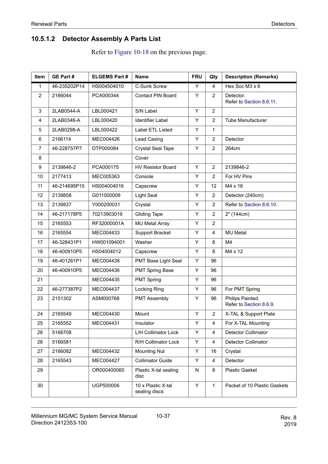
- Chapter 10 – Renewal Parts: FRU definition and codes, Genie acquisition computer and mobile cart, gantry parts (packing material, front, back, roll lock, radial drive, roll motor drive, roll drive gear, IPS assemblies A through H, gantry cable list), hand-held controller, detector assemblies A through D, collimators (LEGP, LEHR, MEGP, HEGP, LEUHS, LE Pinhole), collimator cart assembly, custom tools, collimator cart guide bushing and docking switch, detector interface, MG patient table (basic assembly, subassemblies, upper subassemblies, chassis, vertical drive, rear locating pedal, upper table, lateral plate, lateral motor, left and right E-stop boxes, composite top, longitudinal shade cover, cables)
- Chapter 11 – Troubleshooting and Diagnostics: diagnostic interface, EUI (system calibration, table/gantry status, multiple axis motion setup), Error Log Tool GUI (filters, search, system information), Proactive PMT Analysis (PPA) user interface, troubleshooting the detector (Dyncor analog test, DUI functional description, EDI board test), InSite hardware and software checks, ping and FTP tests, checking the 4-axis motion controller (inputs/outputs, motor servo amplifier LEDs), tightening roll motor encoder set screws, testing collimator locking mechanisms, collecting a GenieAcq error report
- Chapter 12 – Planned Maintenance: tool list, planned maintenance schedule (weekly, 3-month, 12-month, 24-month), procedures for gantry, table, acquisition computer, monitor, keyboard/mouse, mobile cart, detectors and image quality, collimator cart, collimators, gantry and table lubrication, PM procedural checklist
- Appendix A – DICOM Modality Worklist: description, configuring a worklist provider as a remote DICOM station, configuring Genie Acq as a remote station on the worklist provider
- Appendix B – Genie Acq – Vision Connectivity: configuring Genie Acq to Vision P&R station connections
- Appendix C – Genie Acq – eNTEGRA Connectivity: configuring Genie Acq to eNTEGRA P&R station connections
- Appendix D – Installation and Configuration of Other Computer Models: IBM x205, Dell PowerEdge 1400SC, Dell Optiplex GX-200, Dell PowerEdge 1300 – connections, BIOS configuration, ISA configuration, SMC Ethernet board configuration, DOS-based diagnostics, software installation, graphics card and keyboard configurations, monitor and mouse configuration
- Appendix E – 3-Axis Patient Table Specifications: table assembly, covers, chassis, front and rear locating pedals, vertical drive, table top, lateral motor, E-stop boxes, longitudinal drive, composite top, cables
- Appendix F – Preparing the Second Hard Drive: partitioning and formatting the secondary drive
What This Service Manual Enables
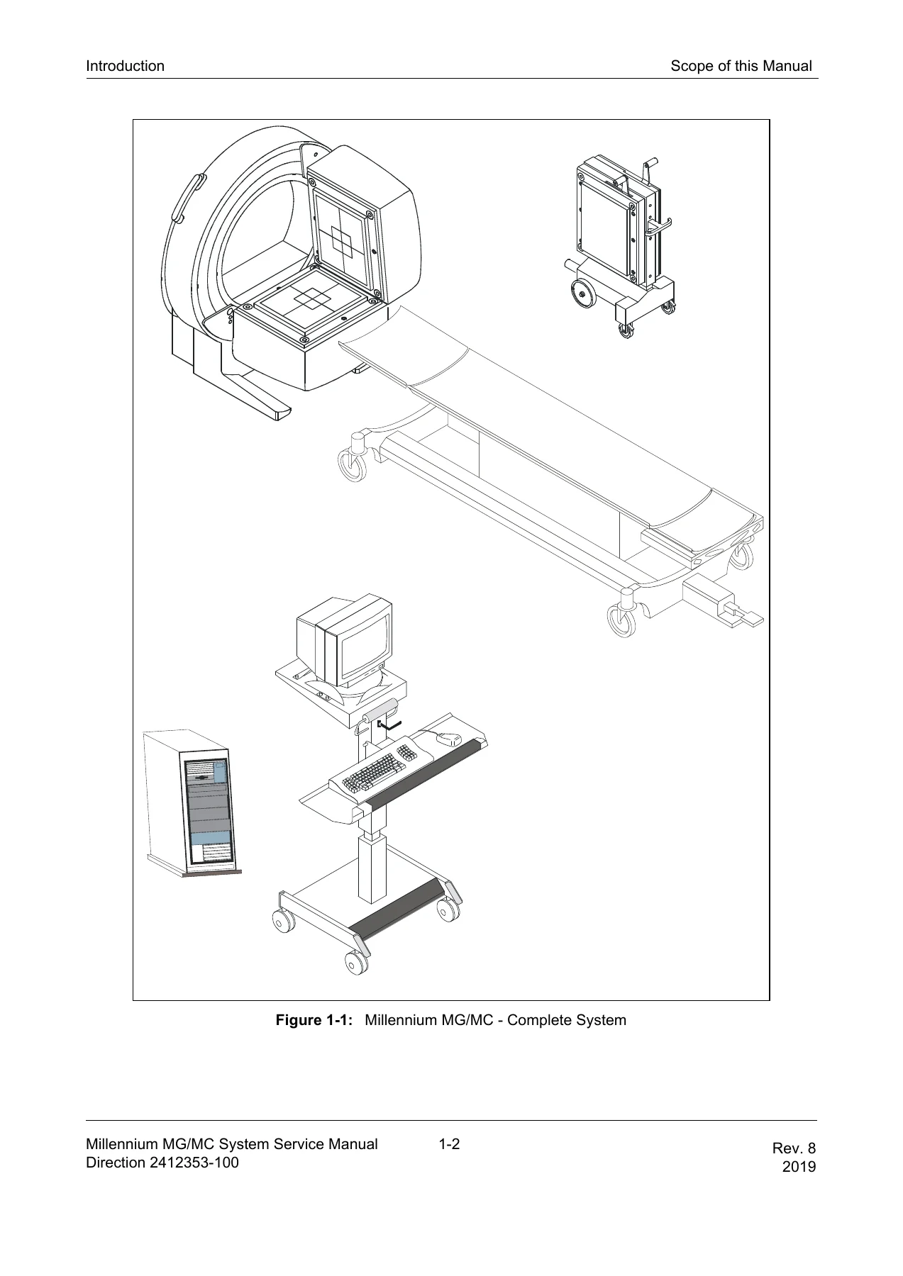
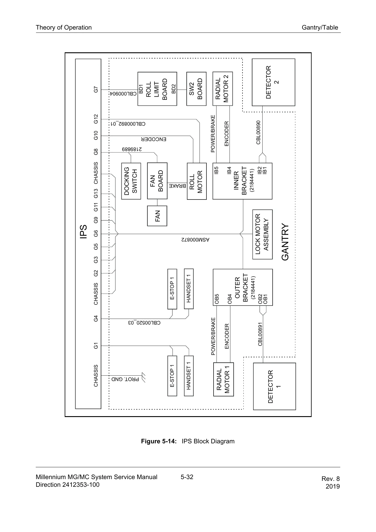
The Millennium MG and MC are ring-gantry nuclear medicine cameras with one or two large field-of-view detectors, a motorized patient table, and an integrated power supply. This manual is the document GE field engineers use to bring a system from delivery through acceptance testing, and to keep it running afterward. It is not a condensed overview — it goes down to board level. You get block diagrams and pinout lists for the gantry, detector, and IPS; torque values for structural fasteners; the full calibration sequence for PMT tuning, Dyncor, energy calibration, geometric calibration, linearity correction, and second-order corrections; and step-by-step procedures for replacing the EDI board, power supply board, matrix board, PMT, cable chains, radial drives, roll-lock assembly, and table drive components.
For a site running Genie Acq Version 4.5 with EDI detectors, the manual also covers the software side in full: installation from CD or DAT tape, patch installation, restoring user data, first-time configuration through the st_config utility, DICOM worklist setup, InSite connectivity, and network printer and remote station configuration. The troubleshooting chapter documents the Diagnostic User Interface, the Exerciser User Interface, the Error Log Tool, and the Proactive PMT Analysis tool, with test-point waveforms and controller LED interpretation tables so faults can be isolated to a field-replaceable unit rather than guessed at.
Who This Manual Is For
This is a working service document for qualified personnel — GE field engineers, third-party service companies with equivalent training, and hospital biomedical departments responsible for the Millennium MG or MC. The safety warnings throughout assume the reader understands electrical, mechanical, and radiation hazards. It is not an operator’s manual and not a training course; it does not replace the Operator’s Reference Manual or the Site Preparation Manual, both of which are referenced inside.
Systems and Software Covered
The procedures apply to the Millennium MG (dual-head) and Millennium MC (single-head) gamma camera systems with the Genie Acquisition computer and the EDI board. Detector and gantry calibration sections assume the EDI-based architecture; systems with earlier I/N boards are covered where the manual explicitly calls them out. The manual also documents configuration of several acquisition computer models that were shipped with this platform over its production life: SuperMicro, IBM x205, Dell PowerEdge 1400SC, Dell Optiplex GX-200, and Dell PowerEdge 1300.
Buy the GE Millennium MG & MC Service Manual
If you maintain a Millennium MG or MC, this manual is the reference that lets you install the system to specification, run the full calibration chain after a detector repair, diagnose a gantry fault from the controller LEDs, or plan a PM visit without hunting through separate documents. It covers the complete service lifecycle of the platform — site planning, installation, functional checks, theory, calibration, board-level interconnect, repair, software, parts, diagnostics, and planned maintenance — in one document.
IMAGES PREVIEW
The file is delivered as an instant PDF download after payment. There is no shipping, no waiting for a disc, and no separate viewer required. You can open it on a laptop at the gantry, print the pages you need for a repair, and search the table of contents by chapter. Every procedure, torque value, wiring list, and part number in this listing comes from Direction 2412353-100 Revision 8, the current revision of the GE Millennium MG & MC Nuclear Medicine Imaging System Service Manual.




Reviews
There are no reviews yet.