
Philips Achieva Multiva Ingenia CX MRI Body Coil 1.5T 3.0T Service Procedures PDF Download
Original price was: $29.95.$18.95Current price is: $18.95.
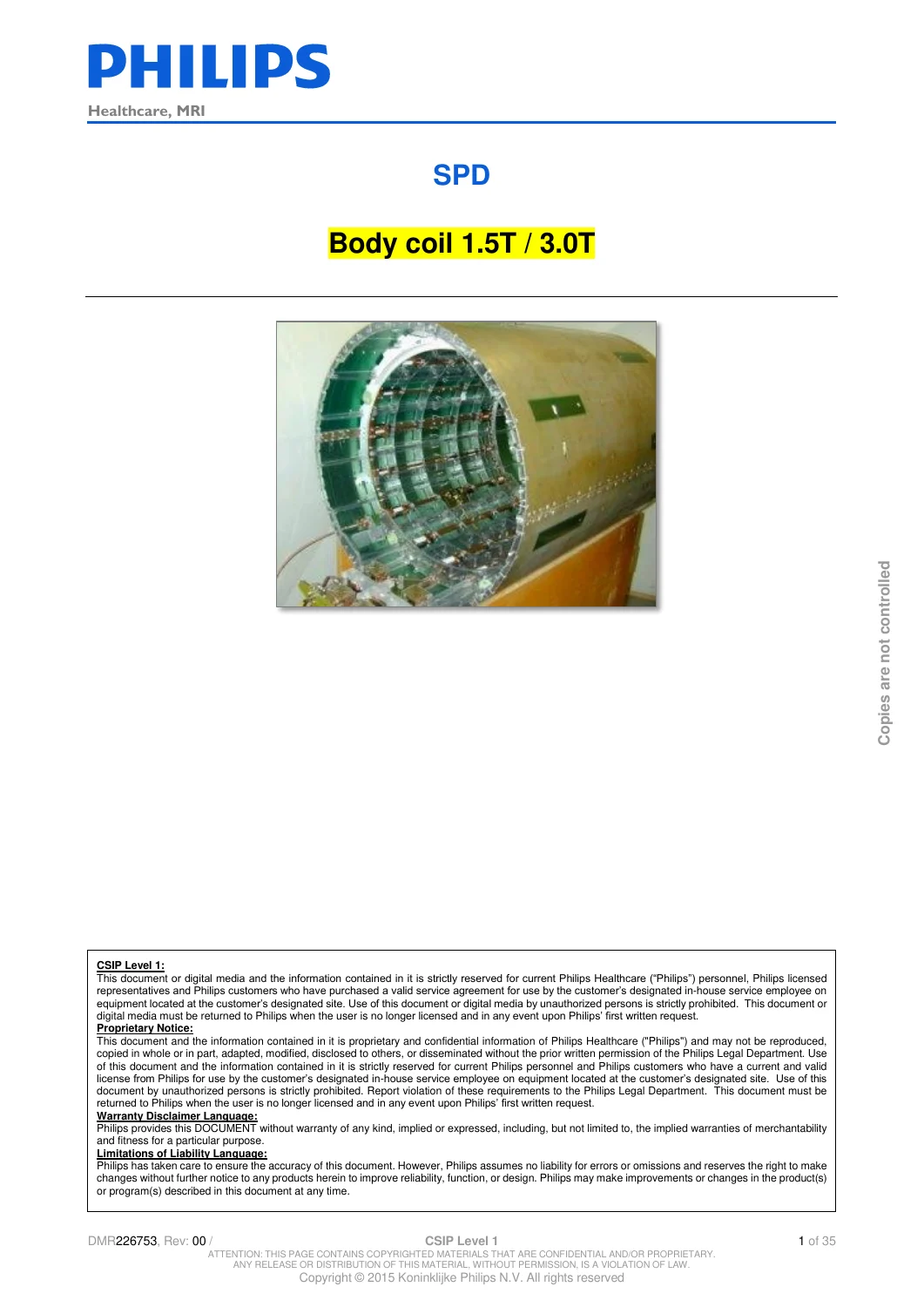
35-page Philips Healthcare MRI service procedure document for Quad Body Coil systems used with Achieva (dStream), Multiva and Ingenia CX 1.5T and 3.0T platforms. Covers detune-board diagnostics, tune and pickup coils, pin-diode and RF-load testing, 1.5T Hybrid Box adjustment, body-coil receive verification, QBC/Booster removal and installation, component replacement and post-repair testing. Instant PDF download.
Description
Philips MRI Body Coil 1.5T / 3.0T Service Procedure Manual
This 35-page Philips Healthcare MRI Service Procedure Document, identified as DMR226753, Revision 00, provides detailed test, diagnostic, adjustment and replacement procedures for the Quad Body Coil used in supported Achieva (dStream), Multiva and Ingenia CX 1.5T and 3.0T MRI systems.
Despite its relatively compact page count, this is a highly focused technical service document. It concentrates specifically on the MRI body-coil assembly and associated RF hardware, including detune boards, tune coils, pickup coils, Hybrid Box electronics, PIN diodes, pre-amplifier biasing, RF load, QBC/Booster assemblies and body-coil receive performance. It also provides extensive physical replacement procedures for 1.5T and 3.0T body-coil configurations.
The document is especially useful as a component-level companion to broader Philips MRI system documentation because it goes directly into the measurements, expected values, service-application menu paths, mechanical removal procedures and post-replacement checks required when working on the body-coil system.
Systems and Equipment Covered
The introduction states that this service procedure document describes procedures for the Quad body coil used in:
- Achieva (dStream)
- Multiva
- Ingenia CX
- 1.5T MRI systems
- 3.0T MRI systems
The procedures are divided according to field strength and body-coil configuration. The document also identifies specific 3.0T arrangements including the QBC/Booster used with the Titan magnet and a separate 3.0T Body Coil used with the REX magnet.
Not every procedure applies to every system configuration. The manual marks 1.5T-only, 3.0T-only and configuration-specific procedures where required. For example, one RF-load test is specifically stated as not applicable to 3T TX systems.
Document Identification
- Document title: Body coil 1.5T / 3.0T
- Document type: SPD – Service Procedure Document
- Product group: Healthcare, MRI
- Document number: DMR226753
- Revision: 00
- Revision date: 30 APRIL 2015
- Language: English
- PDF page count: 35
The document history states that this revision succeeds document 452298127354 and incorporates a newer SPD template, PSC-related menu entries and clerical changes.
Complete Technical Coverage
The manual is organized into four major service areas:
- Programming – Hybrid Box configurations for 1.5T and 3.0T systems
- Test Procedures – electrical and RF checks on body-coil components
- Adjustment Procedures – especially 1.5T Hybrid Box receive adjustment
- Replacement Procedures – physical replacement of body coils, Hybrid Boxes, QBC/Boosters and associated components
An additional appendix provides unpacking and installation instructions for the 3.0T QBC/Booster.
1.5T Body Coil Test Procedures
The 1.5T section contains several targeted diagnostic procedures designed to isolate problems within the body-coil and RF-chain hardware.
Checking the Detune Board
The document explains that each rod of the Quad Body Coil is equipped with a detune board and that a detune-board failure can activate the interlock circuit located on the QDD board.
The procedure includes:
- Accessing the front of the PFEI unit
- Entering the RF coil diagnostic functions through the Service Application
- Selecting Body Coil receive or Tune/Detune functions depending on software version
- Checking the nominal +300 V supply point
- Verifying approximately +275 V at the specified QDD-board measurement point
- Disconnecting MMC-X1 when a detune error is present
- Testing individual PIN diodes using a digital voltmeter in diode-test mode
- Comparing readings across the individual body-coil rods to locate the faulty detune board
The manual provides a rod-by-rod measurement table. Typical PIN-diode forward readings are listed at approximately 480 ± 20 mV. It also distinguishes the matching boards associated with rods 7 and 11.
The document states that the detune and matching boards can be replaced without adjustment in the applicable configuration, while also warning that the two matching boards are not identical.
Testing the 1.5T Tune Coils
The tune-coil test instructs the technician to disconnect the two tune coils from the T/R switch and measure resistance between the shielding and core of the coaxial cables.
The specified resistance is:
- 50 ohms ± 5 ohms
This gives the engineer a direct electrical check for continuity and loading of the tune-coil paths.
Testing PIN Diodes in the 1.5T Hybrid Box
The Hybrid Box contains PIN diodes associated with the RF transmit/receive switching function. The manual explains that these devices help protect the receive pre-amplifiers from transmit RF power.
The test procedure includes separate checks for:
- T/R switch PIN diode
- Input PIN diode switch
- Pre-amplifier biasing
Example diode-test values documented include approximately:
- 530 mV for the specified T/R switch PIN-diode measurement
- 500 mV and 580 mV for specified input PIN-diode measurements
The reverse-polarity checks are expected to show an open condition.
Pre-Amplifier Bias Diagnosis
The manual also provides a useful voltage-based check for the Hybrid Box pre-amplifier supply. The specified interpretations include:
- Approximately 9.7 V – pre-amplifier probably functioning correctly
- Approximately 15.3 V – possible open line, broken wire or defective FET inside the pre-amplifier
- Below 7 V – possible overloaded supply, wiring short or shorted FET
The associated coaxial cable can then be checked separately for shorts or open conductors.
Testing the Pickup Coils
The pickup-coil test uses a digital voltmeter to measure resistance between the core and shield. Both the combined circuit and individual pickup coils can be checked.
The specified value is:
- 50 ohms ± 5 ohms
Testing the RF Load / QBC Load
The 1.5T procedure also includes a direct test of the RF load, also called the QBC load. The coaxial cable is disconnected from the Hybrid Box and resistance is measured between the cable core and shield.
The specified resistance is:
- 50 ohms ± 5 ohms
3.0T QBC / Booster Test Procedures
The manual contains a separate technical sequence for the 3.0T QBC/Booster. The procedures recognize the different behavior and configuration of the 3T body-coil hardware rather than simply repeating the 1.5T instructions.
3.0T Detune-Board Diagnostics
As with the 1.5T system, each Quad Body Coil rod contains a detune board and failures may activate the QDD-board interlock circuit.
The procedure includes:
- PFEI access
- RF coil diagnostics through the Service Application
- Body Coil receive / Tune-Detune selection
- Checking the +300 V supply path
- Expected reading of approximately +275 V at the specified point
- Individual PIN-diode measurements across the QBC rod connections
- Comparison of forward-voltage values to identify an abnormal diode or detune board
The body-coil rod table again shows typical readings around 480 ± 20 mV.
3.0T Tune and Pickup Coil Testing
The 3.0T QBC/Booster section includes testing of the tune/pickup-coil circuit. Resistance is measured between the coaxial cable core and shield.
Specified resistance:
- 50 ohms ± 5 ohms
3.0T RF Load Test
A 50-ohm RF-load test is provided for applicable 3.0T configurations. The manual explicitly notes that this procedure is not for 3T TX systems.
Specified resistance:
- 50 ohms ± 5 ohms
3.0T Body Coil Receive Test
The manual contains a dedicated Body Coil Receive Test for the 3.0T QBC. This procedure examines receive-frequency offset and Q-factor using a linear flux probe positioned at two modes of the Quad Body Coil.
The manual explains that the unloaded 3.0T QBC receive frequency is normally shifted from the system resonance frequency and that the observed center frequency is affected by transceiver hardware limitations and whether the magnet is on field.
The procedure includes:
- Removing the inner bed where applicable
- Installing the linear flux probe in the QBC flux-probe holder
- Connecting the probe to the tune-A signal
- Positioning the probe at mode 3-11
- Running Body coil verification (RX) through the applicable service menu
- Recording frequency offset and Q-factor
- Moving the probe to mode 7-15
- Repeating frequency measurements
- Calculating the average Q-factor
- Comparing the results with the documented typical-value tables
3.0T Typical Values – Magnet Not On Field
- Probe position 3-11: -200 kHz ± 150 kHz
- Probe position 7-15: -100 kHz ± 150 kHz
- Calculated average Q-factor: greater than 210
3.0T Typical Values – Magnet On Field
- Probe position 3-11: -150 kHz ± 150 kHz
- Probe position 7-15: -100 kHz ± 150 kHz
- Calculated average Q-factor: greater than 280
The document also contains a correction note relating to the offset frequency used in R1.1 and explains how the resulting frequency-offset values should be corrected.
1.5T Body Coil Adjustment Procedures
The adjustment section makes an important distinction between permitted field adjustments and adjustments that are not intended to be performed on site.
The manual states that technicians must not readjust the separated modes by turning the trimmers in the QBC rods. After QBC replacement, the documented Hybrid Box adjustment (RX) is considered sufficient.
Tools Listed for 1.5T Hybrid Box Adjustment
- QBC flux probe holder: 4522 130 9622*
- Rotation knob: 4522 131 0740*
- 15 metre 50-ohm coaxial cable: 4522 131 6722*
Hybrid Box Receive Adjustment
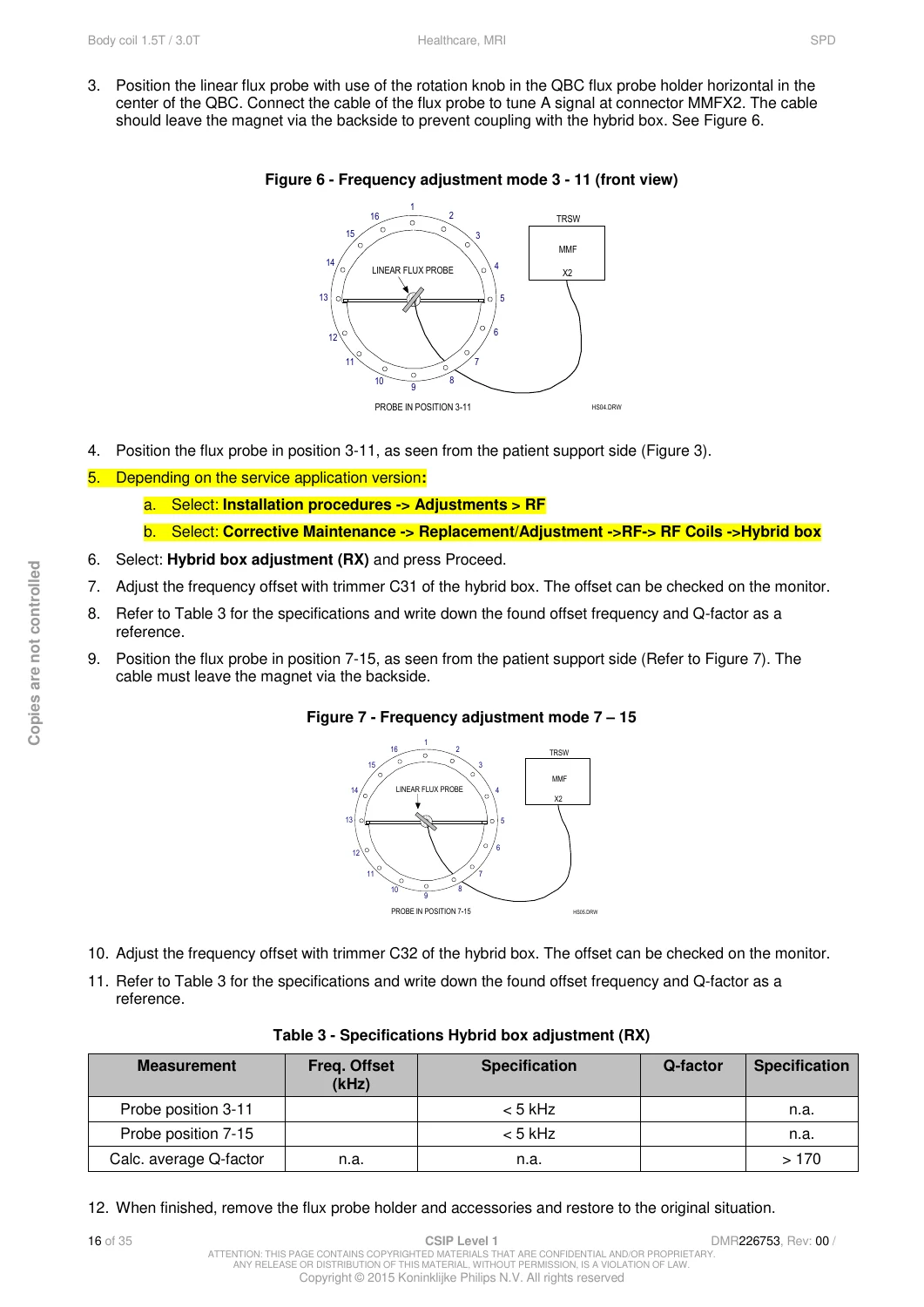
The Hybrid Box adjustment uses two trimmers, C31 and C32, to adjust the frequency offset of the two QBC modes.
The manual illustrates the Hybrid Box and identifies the physical location of the trimmers. The procedure then guides the technician through:
- Access to the Hybrid Box
- Use of the PHD where present
- Installation of a linear flux probe in the QBC
- Probe positioning at mode 3-11
- Entering the RF adjustment / Hybrid Box adjustment function in the Service Application
- Adjusting frequency offset using C31
- Recording frequency offset and Q-factor
- Moving the probe to mode 7-15
- Adjusting frequency offset using C32
- Recording the second measurement
- Calculating the average Q-factor
1.5T Hybrid Box Adjustment Specifications
- Probe position 3-11 frequency offset: less than 5 kHz
- Probe position 7-15 frequency offset: less than 5 kHz
- Calculated average Q-factor: greater than 170
If the calculated average Q-factor is below specification and the image-quality performance measurements are also outside specification, the manual states that adjustment of the complete body coil is necessary and that this complete adjustment cannot be performed in the field.
3.0T Adjustment Limitations
The 3.0T body-coil section clearly states that the body coil is factory adjusted. Frequency adjustment is described as unnecessary and not possible on site.
This is important for troubleshooting because it prevents technicians from attempting a field adjustment that the document does not support.
1.5T Body Coil Removal and Replacement
The replacement section provides a detailed mechanical sequence for removing the 1.5T Quad Body Coil from the MRI system.
Major steps include:
- Positioning the patient table
- Switching the FEPSU off
- Switching the Gradient System off
- Removing front and rear cone covers
- Removing dust strips and the bridge section
- Disconnecting Hybrid Box cabling
- Removing the Hybrid Box top plate
- Disconnecting the Hybrid Box from the QBC and gradient coil
- Releasing QBC/Hybrid cabling
- Disconnecting the PFEI-side cables
- Removing Hybrid Box mounting bolts
- Releasing front and rear QBC eccentric supports
- Removing rear QBC retaining screws
- Removing pickup coils
- Disconnecting the earth connection
- Removing the front gradient-carrier component
- Sliding the QBC out of the gradient coil
- Transferring applicable covers from the old QBC to the replacement assembly
Installing a Replacement 1.5T Body Coil
The installation procedure covers:
- Positioning the replacement QBC inside the gradient coil
- Checking that the QBC is correctly oriented
- Aligning the QBC with existing brackets
- Setting lower and upper eccentric supports
- Securing the body-coil position
- Reinstalling the gradient-carrier component
- Restoring the earth connection
- Reinstalling Hybrid Box mounting hardware
- Reconnecting the QBC to the Hybrid Box
- Restoring cables and covers
After physical QBC replacement, the manual directs the engineer into the Replacement/Adjustment Procedures → RF → RF Coils → Body Coil path and instructs that the complete sequence of applicable tests and adjustments be performed.
1.5T Hybrid Box Replacement
A dedicated procedure covers physical replacement of the 1.5T Hybrid Box.
The manual identifies its position in the magnet bore, under the bridge section and in front of the QBC. The replacement procedure includes:
- FEPSU shutdown
- Gradient System shutdown
- Removal of cone covers
- Removal of the bridge section
- Disconnecting all Hybrid Box cables
- Removing the Hybrid Box top plate
- Disconnecting the Hybrid Box from the QBC
- Removing it from the gradient coil
- Correct placement of isolation and metal washers during installation
- Attention to RF grounding/contact requirements
- Correct reconnection of cables
- Performing the complete Body Coil/Hybrid Box test and adjustment sequence afterward
The manual specifically warns that some connectors use the same connector type, making correct cable reconnection important.
3.0T QBC / Booster Replacement – Titan Magnet
The document includes substantial mechanical instructions for removing and installing the 3.0T QBC/Booster associated with the Titan magnet.
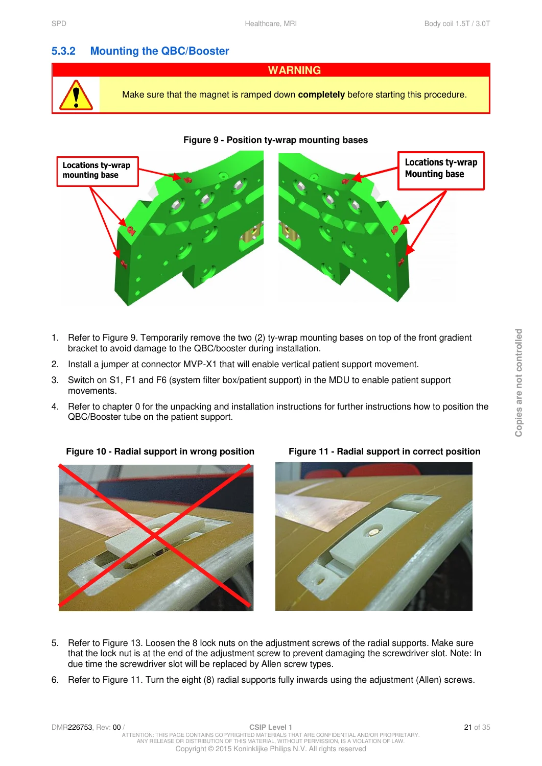
A prominent safety condition requires the magnet to be completely ramped down before this procedure is started.
The disassembly and installation procedures address:
- FEPSU shutdown
- Gradient System shutdown
- Removal of cone covers and bridge section
- Temporary patient-support movement configuration
- Protection of QBC/Booster hardware during movement
- Z-axis adjustable stops
- Disconnection of QBC cabling
- Removal of mounting hardware
- Protective film installation
- Radial-support adjustment
- Positioning of the QBC/Booster on the patient support
- Correct and incorrect radial-support positions
- Mechanical alignment of the replacement assembly
- Reinstallation and final testing
3.0T Body Coil Replacement – REX Magnet
A separate section covers dismounting and installation of the 3.0T Body Coil for the REX magnet. This is not treated as identical to the Titan QBC/Booster configuration.
The procedure includes detailed mechanical alignment requirements, positioning and radial-support adjustment. Documented dimensional checks include:
- An approximately 2-3 mm equal gap between the Body Coil tube and gradient coil at the specified adjustment stage
- Verification of a required 50 mm distance between the Body Coil tube and gradient carriers
The manual also provides instructions for securing the QBC connectors and references the appropriate data-acquisition-system drawing for restoring cabling after installation.
After exchange, the complete service-application Body Coil test and adjustment sequence must be performed.
3.0T Hybrid Box / QIB Replacement
The manual contains another dedicated procedure for Hybrid Box/QIB replacement on 3.0T systems.
Coverage includes:
- Location of the Hybrid Box below the gradient carrier at the front of the magnet
- FEPSU shutdown
- Gradient System shutdown
- Front-cover removal
- Cable disconnection
- Removal of the existing Hybrid Box
- Installation of the replacement Hybrid Box
- Reconnection of all cables
- Body Coil receive measurement following replacement
- Running the required RF Coil replacement and adjustment procedures
Pickup Coil Replacement Follow-Up
The manual notes that the physical replacement of the pickup coil is considered self-evident and therefore does not provide a long mechanical procedure. It does specify the required testing and adjustment after replacement.
Applicable service functions include:
- RF Power Reference Calibration – Body Coil
- Pickup Coil Triplevel Calibration – Body Coil
- Corresponding Corrective Maintenance / Replacement-Adjustment RF Coil functions depending on Service Application version
50-Ohm QBC Load Replacement
Following replacement of the 50-ohm QBC load, the manual instructs the technician to enter the RF Coil replacement/adjustment section, select the 50 Ohm load Body Coil procedure and complete the associated tests and adjustments.
Detune and Matching Board Replacement
The manual includes service guidance for detune and matching boards. It states that no adjustment or test is required after replacement in the specified procedure and notes that, for 3.0T systems, the matching boards are not defined as an FRU.
3.0T QBC / Booster Unpacking and Installation Appendix
The final section contains illustrated unpacking and installation instructions for the 3.0T QBC/Booster.
The sequence includes:
- Opening the shipping crate
- Removing crate sides and lid
- Locating the supplied couch platform
- Removing the couch platform from beneath the QBC module
- Removing foam packing components
- Positioning the QBC crate platform beside the patient table
- Using the patient table/couch platform to align the assembly
- Sliding the QBC platform into position
- Aligning the QBC with the gradient-tube bore
The appendix includes photographs that make the physical handling sequence considerably clearer than text-only installation instructions.
Important Specifications and Test Values Included
Among the useful values printed in the manual are:
- 1.5T detune PIN diodes: typical approximately 480 ± 20 mV
- 1.5T tune coil resistance: 50 ohms ± 5 ohms
- 1.5T pickup coil resistance: 50 ohms ± 5 ohms
- 1.5T RF/QBC load resistance: 50 ohms ± 5 ohms
- Hybrid Box pre-amplifier diagnostic: approximately 9.7 V normal indication; 15.3 V open-line indication; below 7 V overload/short indication
- 1.5T Hybrid Box adjustment frequency offset: less than 5 kHz at both measured modes
- 1.5T Hybrid Box calculated average Q-factor: greater than 170
- 3.0T QBC detune supply check: approximately +275 V at the specified measurement point
- 3.0T tune/pickup coil resistance: 50 ohms ± 5 ohms
- 3.0T RF load resistance: 50 ohms ± 5 ohms where applicable
- 3.0T average Q-factor, magnet not on field: greater than 210
- 3.0T average Q-factor, magnet on field: greater than 280
Illustrations and Technical Detail
The PDF includes photographs, component views, connection information, probe-position drawings and mechanical installation illustrations. Examples include:
- 1.5T Hybrid Box internal/component view
- 3.0T Hybrid Box view
- Hybrid Box trimmer locations C31 and C32
- QBC flux-probe positions for modes 3-11 and 7-15
- Rear bridge-carrier arrangement
- QBC/Booster support and mounting locations
- Correct versus incorrect radial-support positioning
- Mechanical alignment and installation details
- 3.0T QBC/Booster unpacking and transfer photographs
What This Manual Is
- A focused Philips MRI Quad Body Coil service procedure document
- A 1.5T and 3.0T body-coil diagnostic guide
- A detune-board and PIN-diode troubleshooting reference
- A tune-coil and pickup-coil test reference
- A Hybrid Box test and adjustment guide
- A body-coil receive-performance verification reference
- A QBC/Booster removal and installation guide
- A Body Coil and Hybrid Box replacement guide
- A post-replacement testing and adjustment reference
- A useful supplement for Achieva, Multiva and Ingenia CX service work where the Body Coil/RF subsystem is involved
What This Manual Does Not Cover
This PDF is deliberately focused on the Body Coil and closely associated RF hardware. It should not be mistaken for an entire MRI system service library.
- It is not a complete Multiva, Achieva or Ingenia CX system installation manual.
- It is not a general operator or scanning-protocol manual.
- It is not a complete MRI image-quality troubleshooting manual.
- It is not a magnet ramping or shimming manual.
- It is not a complete gradient-system service manual.
- It is not a comprehensive electrical schematic or circuit-board schematic collection.
- It is not a parts catalog.
- It does not provide every service procedure for every RF coil used on the supported MRI systems.
- For the 3.0T Body Coil, the document explicitly states that field frequency adjustment is not necessary and is not possible on site.
Why This Manual Is Useful
When an MRI Body Coil problem is suspected, broad system manuals can require considerable searching before the relevant tests are found. This SPD concentrates the essential Body Coil procedures into one technical reference: what to measure, where to measure it, which Service Application function to select, what readings are expected, which mechanical components must be removed and what tests must be completed after replacement.
For Philips Multiva 1.5T service work in particular, this document is a strong companion to the larger Multiva System Manual Installation because it adds focused Body Coil diagnostic and repair procedures that are not presented with this level of component-specific detail in the general system-installation workflow.
The combination of explicit electrical measurements, Hybrid Box adjustment procedures, body-coil receive verification and full physical replacement sequences makes this document useful when diagnosing or replacing a QBC, Hybrid Box, detune board, pickup coil, RF load or related body-coil hardware.
Technical Use and Safety
The procedures involve MRI RF hardware, high voltages, magnet-field conditions, system covers, patient-support movement and Service Application functions. The manual contains specific shutdown and safety requirements, including FEPSU and Gradient System isolation and, for the specified 3.0T QBC/Booster procedure, complete magnet ramp-down. These procedures are intended for appropriately trained service personnel working with the applicable equipment configuration.
Instant PDF Download
This product is supplied as a 35-page digital PDF. After payment is completed, the document is available for immediate download and can be retained as a technical service reference on a compatible computer, tablet or mobile device.
No printed book is shipped. You receive the downloadable PDF document described on this page.
Reviews
There are no reviews yet.