
GE Vivid E9 / Vivid E7 with XDclear BT’13 Service Manual – GB091046 Rev 2 PDF
Original price was: $49.95.$32.95Current price is: $32.95.
Service manual for GE Vivid E9 and Vivid E7 with XDclear BT’13, document GB091046 Rev 2. Covers site preparation, system setup, functional checks, theory, service adjustments, troubleshooting, replacement procedures, renewal parts, and care and maintenance.
Description
GE Vivid E9 / Vivid E7 with XDclear BT’13 Service Manual – GB091046 Rev 2
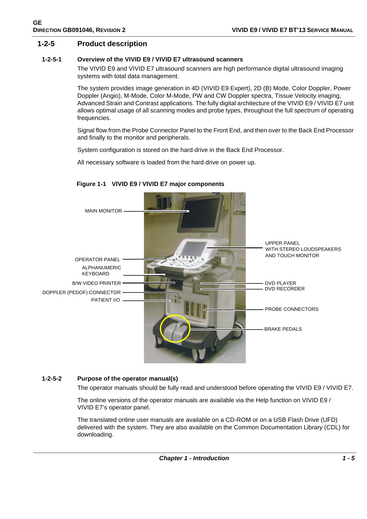
This GE Vivid E9 / Vivid E7 with XDclear BT’13 Service Manual – GB091046 Rev 2 provides installation, service, and maintenance information for the VIVID E9 and VIVID E7 ultrasound scanning systems. The document is identified as Direction GB091046, Revision 2, and is written in English. It is organized into ten chapters plus an index, with service safety warnings, system descriptions, procedures, replacement instructions, renewal parts listings, and care and maintenance guidance. The manual is intended for service personnel, hospital service personnel, and installation or architectural planners for the relevant sections.
File Details
- Manual type: Service Manual
- Brand: GE
- Equipment: VIVID E9 / VIVID E7 with XDclear BT’13
- Document number: GB091046
- Revision: 2
- Revision date: 2016-JAN-29
- Language: English
- Page count: 736
- File format: PDF
Chapters Covered
- Chapter 1 – Introduction: service manual overview, important conventions, safety considerations, dangerous procedure warnings, Lockout/Tagout requirements, returning and shipping probes and repair parts, electromagnetic compatibility, and customer assistance.
- Chapter 2 – Site preparations: general console requirements, environmental requirements, electrical requirements, EMI limitations, probe environmental requirements, time and manpower requirements, facility needs, purchaser responsibilities, required and desirable facility features, floor plan suggestions, and networking setup requirements.
- Chapter 3 – System setup: setup reminders, receiving and unpacking, preparing for setup, completing the setup, system and electrical specifications, I/O rear panel and Patient I/O connections, probe connection, power on and shut down, configuration, service screen setup, optional peripherals, software option configuration, connectivity overview and setup, DICOM and TCP/IP settings, DHCP setup, remote archive setup, dataflow creation, options setup, and setup paperwork.
- Chapter 4 – General procedures and functional checks: power on and boot up, power shut down, top console position adjustment, LCD monitor position adjustment, logging on as ADM, moving and transporting the system, recording important settings and parameters, cleaning the trackball, functional checks for 2D mode, M mode, color mode, PW/CW Doppler, Tissue Velocity Imaging, probes and connectors, ECG, cineloop, back end processor, operator panel, peripherals, mechanical functions, and site log.
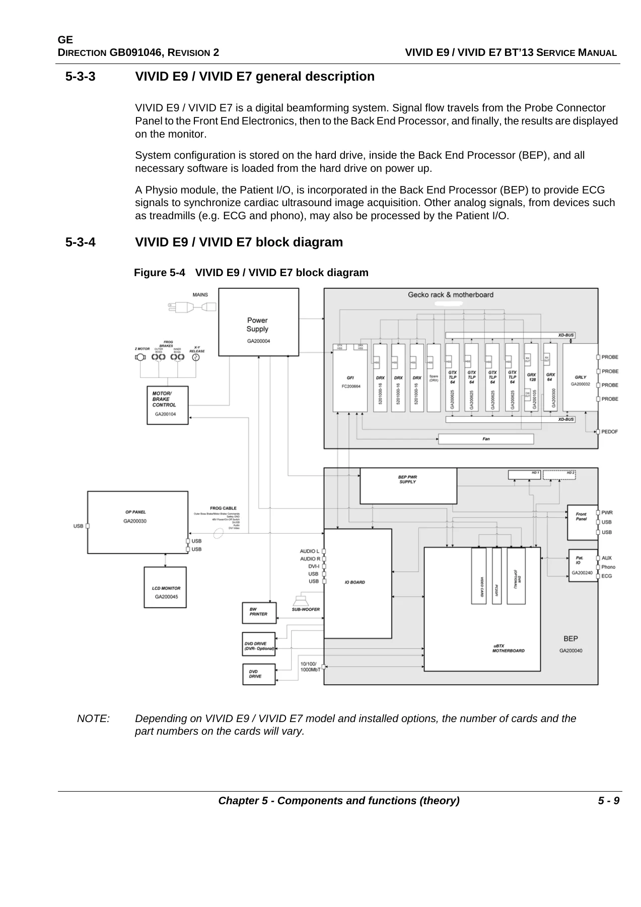
- Chapter 5 – Components and functions (theory): InSite ExC, VIVID E9 and VIVID E7 overview, block diagrams, signal flow, system configuration and software, electronics, interconnection diagram, operating modes, top console with LCD monitor and operator panel, main console, air flow control, casters and brakes, front end processor, transmitter and receiver subsystem, relay board, receiver board, front plane boards, digital receiver board, GFI board, FEP backplane, back end processor, power distribution, I/O modules, peripherals overview, product manuals, and common service desktop overview.
- Chapter 6 – Service adjustments: LCD monitor adjustments, LCD arm and monitor range of motion, backlight adjustment, touch screen calibration, DC offset calibration and front end alignment, XYZ mechanism adjustment, XY lock adjustment, XY manual release for lock and brake mechanism, park lock use, Z mechanism adjustment, and DICOM server time-out adjustment.
- Chapter 7 – Diagnostics and troubleshooting: service safety considerations, frequently asked questions, high system temperature error, resetting the BEP from a hang, releasing the top console when power is unavailable, troubleshooting tips, shortcut keys, image artifacts caused by front end boards, back end processor issues, operator panel issues, probe recognition, software issues, network connectivity troubleshooting, gathering troubleshooting data, screen captures, motor controller test, lock-up and unable-to-scan troubleshooting, XY lock and brake motor troubleshooting, Z movement failures, keyboard lock and release issues, USB footswitch and USB device issues, TEE probe temperature, system temperature, and noise troubleshooting.
- Chapter 8 – Replacement procedures: warnings and important information, definitions of left, right, front, and back, reloading the software, replacing covers and bumpers, top console parts replacement, replacing XYZ parts, main console parts replacement, casters and brakes replacement, front end processor and card cage parts replacement, back end processor parts replacement, main power supply replacement, I/O modules replacement, and peripherals replacement.
- Chapter 9 – Renewal parts: definitions, abbreviations, model and hardware/software compatibility, software overview, covers and bumpers, top console parts, LCD monitor parts, operator panel parts, top console PCBs, trackball parts, operator panel cable kit, button kits and knobs, alphanumeric keyboard parts, common top console parts, XYZ parts, main console parts, casters and wheels parts, front end processor card rack parts, back end processor spare parts, main power supply, I/O modules, peripherals, mains power cables, internal cables, ECG cables, Physio TX parts, options, and product manuals.
- Chapter 10 – Care and maintenance: periodic maintenance inspections, why maintenance is performed, keeping records, quality assurance, maintenance task schedule, tools required, system maintenance, preliminary checks, functional checks, physical inspection, cleaning, probe maintenance, electrical safety tests, leakage current limits, grounding continuity, chassis leakage current test, isolated patient lead leakage tests, probe leakage current test, and guidance when leakage current is too high.
- Index: a quick-reference index to topics throughout the service manual.
Across these chapters, the GE Vivid E9 / Vivid E7 with XDclear BT’13 Service Manual – GB091046 Rev 2 gives service technicians a structured path from site planning and system setup through functional verification, theory of operation, adjustments, diagnostics, replacement procedures, spare parts identification, and ongoing maintenance. The content is specific to the VIVID E9 and VIVID E7 platforms and includes safety warnings, Lockout/Tagout requirements, EMC considerations, electrical safety tests, and detailed replacement procedures for major assemblies and modules.
Coverage for VIVID E9 and VIVID E7 Systems
The manual lists VIVID E9 models GB000070, GB000080, GB000075, GB000085, GB000090, and GB000095, plus VIVID E7 models GB000099 and GB000100. It documents hardware and software compatibility tables, including front end processor card rack and back end processor details, and it references XDclear software version 113 and system software version 104.3.5 or higher where applicable. Vivid E9 Vet information is also referenced in the revision history. The service manual is available in English only, and the translation policy section states that translation services are the customer’s responsibility if another language is required.
How the Manual Supports Service Work
For technicians working on VIVID E9 or VIVID E7 ultrasound scanners, this service manual provides procedures for receiving and unpacking the equipment, verifying site requirements, connecting probes and peripherals, configuring network and DICOM settings, running functional checks, and performing service adjustments. The theory chapter explains the front end processor, back end processor, power distribution, I/O modules, and system signal flow. The diagnostics and troubleshooting chapter includes guidance for lock-ups, network connectivity, image artifacts, probe recognition, temperature issues, motor controller tests, and USB device problems. The replacement procedures chapter covers covers and bumpers, top console components, XYZ mechanisms, casters and brakes, front end processor boards, back end processor components, the main power supply, I/O modules, and peripherals.
Safety and Service Planning Content
Safety content appears throughout the manual, including electrical safety, mechanical safety, human safety, ESD prevention, Lockout/Tagout requirements, and dangerous procedure warnings. The care and maintenance chapter includes electrical safety tests such as grounding continuity, chassis leakage current, isolated patient lead leakage, and probe leakage current tests, with leakage current limits for different mains configurations. Site preparation content covers environmental requirements, electrical requirements, EMI limitations, facility needs, floor plan suggestions, and networking setup requirements. These sections support planning before installation and help service personnel follow safety and compliance practices during maintenance and repair.
Get the PDF Service Manual
IMAGES PREVIEW
The GE Vivid E9 / Vivid E7 with XDclear BT’13 Service Manual – GB091046 Rev 2 is delivered as an instant PDF download with no shipping. It can be viewed on a computer, tablet, or phone and printed for use in the service environment. This manual supports setup, maintenance, troubleshooting, adjustment, and replacement work on the covered VIVID E9 and VIVID E7 systems, giving technicians access to the documented procedures, safety warnings, component descriptions, renewal parts information, and electrical safety test guidance needed to carry out service tasks correctly.


Reviews
There are no reviews yet.