
GMM Calypso AFS X-Ray System Stand Table & Wall Stand Technical Manual Set
Original price was: $39.95.$23.95Current price is: $23.95.
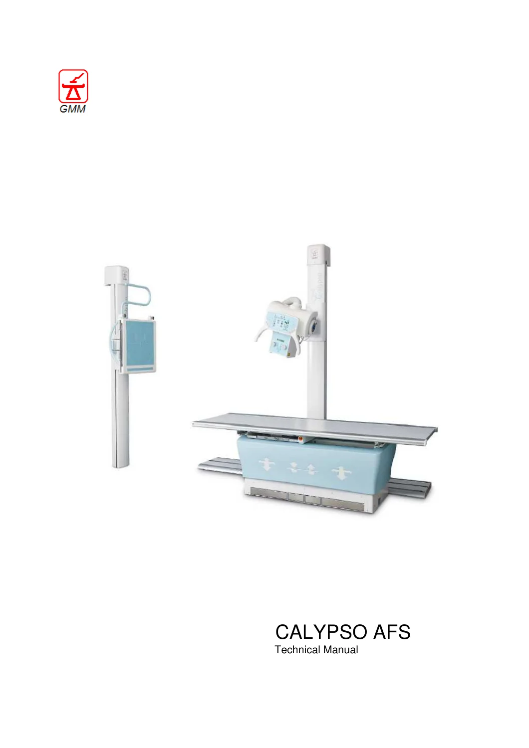
235-page technical manual collection for the GMM Calypso AFS radiographic system, covering the TS7630-ST floor-mounted X-ray tube support, ET8530/ET8532 elevating tables, BT7630/BT7632 fixed-height radiography tables and TRN/TRT wall stand configurations. Includes installation, mechanical assembly, adjustments, electrical connections, technical specifications, maintenance procedures, safety information and illustrated component guidance.
Description
GMM Calypso AFS X-Ray System Stand Table & Wall Stand Technical Manual Set
This GMM Calypso AFS X-Ray System Stand Table & Wall Stand Technical Manual Set brings together technical documentation for the principal mechanical support equipment used in the Calypso radiographic installation. The material covers the floor-mounted X-ray tube support, elevating and fixed-height radiography tables, and vertical wall stand, with detailed information intended for installation, setup, servicing, adjustment and scheduled maintenance work.
The collection is particularly useful when working on a complete installation rather than a single isolated component. The main Calypso technical manual explains how the tube stand, table and wall stand are planned, positioned, assembled and aligned as a system. Additional component-specific manuals then provide dedicated technical coverage for the BT7630/BT7632 fixed-height table, ET8530/ET8532 elevating bucky table and TRN430 vertical bucky stand.
File Details
- Manual type: Technical manual collection
- System: GMM Calypso AFS
- Language: English
- Page count: 235 pages
- File format: PDF
- Main manual: TM76301-EN Rev.0, 2018JUL
- Fixed-height table manual: BT7630MTE00, 19-06-2018
- Elevating table manual: ET85MTE30 Rev.0, 28/04/2017
- Vertical bucky stand manual: TRN4MTE3A, 22/02/2017
System and Equipment Coverage
The main technical manual identifies the TS7630-ST floor stand for X-ray tube support together with Calypso-F/M and Calypso/AFS applications. It also identifies compatible elevating table equipment including ET8530, ET8532 and MTOE/M, plus wall stand units TRN430, TRN43D, TRN43X, TRT430, TRT43D and TRT43X. The separate fixed-height table manual covers BT7630, BT7632 and MTOp.
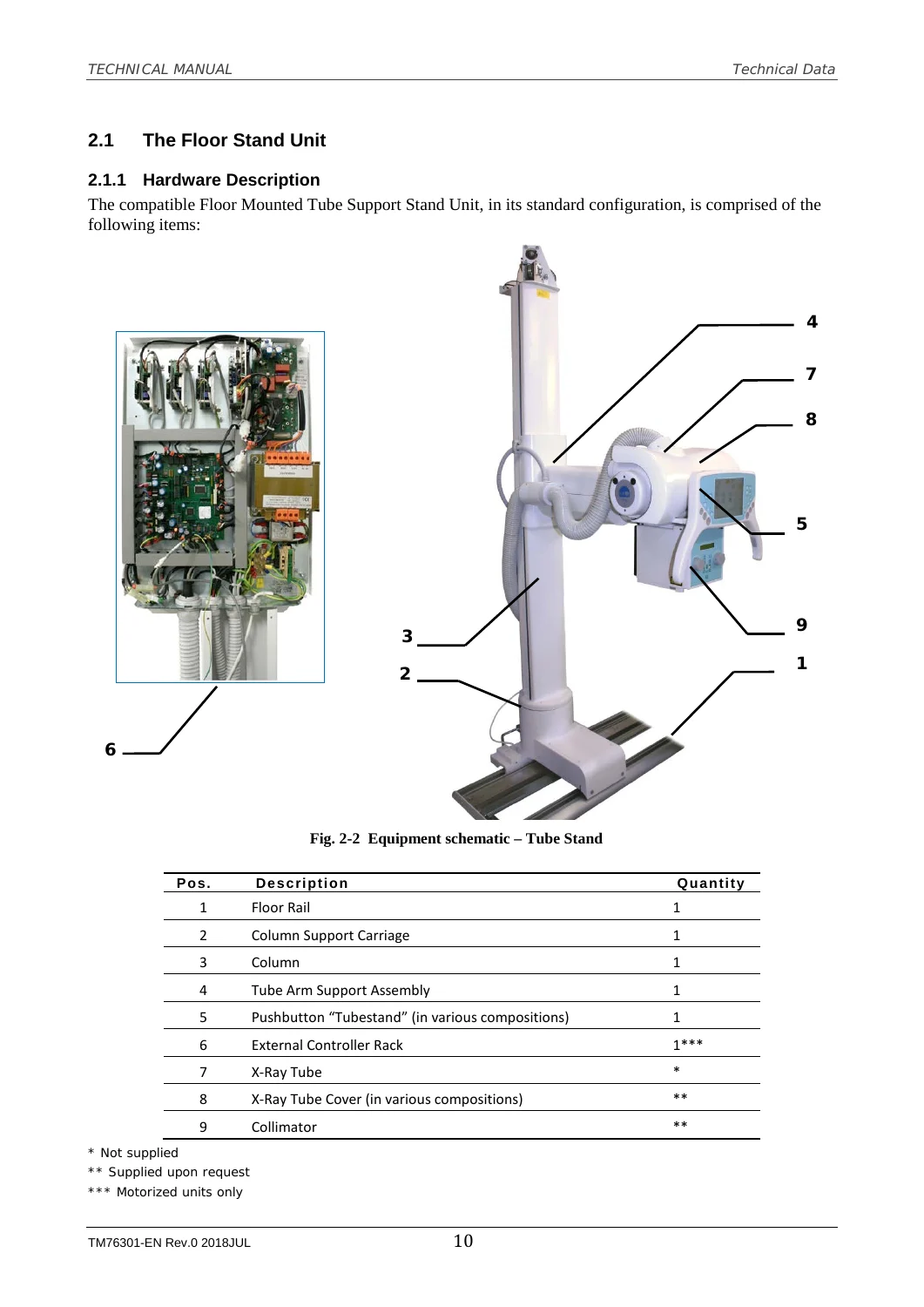
Technical data sections describe the physical construction and movement characteristics of the major assemblies. The TS7630-ST information includes its floor rail, column support carriage, tube arm, control station, optional motorized movement, electromagnetic braking, counterweight balancing and controller communication. Dedicated table and wall stand sections likewise document their receptor supports, movements, braking arrangements, electrical requirements, weights and installation conditions.
Chapters Covered
- Calypso / TS7630-ST system technical manual
- General information and manual conventions
- System description and technical data
- Floor stand hardware description and specifications
- Elevating table hardware description and specifications
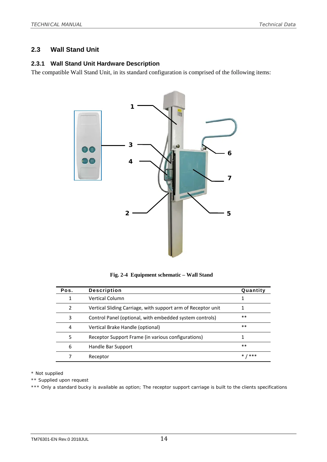
- Wall stand hardware description and specifications
- Transport, stocking and operating ambient conditions
- Technical designs and identification labeling
- Safety, electrical precautions and radiation hazards
- System installation and pre-planning
- Room preparation, receiving, inventory and unpacking
- Equipment positioning and technical drawings
- Floor rail and ET8530/ET8532 table installation
- Wall stand mounting and fixing arrangements
- Tube support stand mechanical assembly
- X-ray tube, headcuff, support and collimator mounting
- Electrical parts and high-tension cable assembly
- Tube stand balancing
- Table unit mechanical assembly and receptor installation
- AEC installation and table electrical connections
- Wall stand receptor and electrical connections
- Mechanical alignment and adjustments
- Primary beam, light field and receptor alignment
- Tube inclination and support-arm regulation
- Equipment decommissioning
- Maintenance, periodic controls, wire-rope inspection, cleaning and disinfection
- BT7630 / BT7632 fixed-height radiography table
- Equipment description and technical specifications
- Patient table top and bucky carriage
- Optional accessories and technical designs
- Safety measures and radiation precautions
- Room preparation and equipment receiving
- Positioning and fixing the bucky table
- Receptor, docking station and fixed-panel installation
- Guide-bearing and table-top brake adjustment
- AEC unit installation
- Mains and bucky electrical connections
- External OEM controller connections
- Decommissioning and maintenance
- ET8530 / ET8532 elevating bucky table
- General information and safety measures
- Equipment components and technical features
- Patient table top, bucky carriage and controls
- Additional components and optional accessories
- Installation, warehousing, transport and receiving
- Fixing and mounting procedures
- Bucky and patient table-top connections
- Guide and roller bearing regulation
- Maintenance schedule and general checks
- Equipment disassembly and maintenance register
- TRN430 vertical bucky stand
- General information and safety measures
- Equipment description and technical features
- Standard model variations and accessories
- Installation and room preparation
- Equipment receiving and positioning
- Support-base and wall/floor fixing
- Bucky mounting and vertical-carriage unlocking
- Vertical carriage balancing
- Electrical connections
- Maintenance schedule, wire ropes and suspension cables
- Cleaning, disinfection and equipment disassembly
Taken together, these sections give the installer or service technician a coordinated reference for the mechanical structure of the Calypso equipment, the preparation of the radiographic room, equipment placement, receptor installation, electrical interconnections, alignment and long-term maintenance. The manuals also contain technical drawings, equipment schematics, component illustrations, installation layouts and adjustment figures that support the written procedures.
Installation, Assembly and Alignment Information
A substantial portion of the GMM Calypso AFS X-Ray System technical manual is devoted to installation. It starts with room planning and construction requirements, cable routing, receiving and inventory checks, then progresses through positioning the main units. Procedures address fixing the TS7630-ST floor rails, inserting the tube stand into the rail, installing the table and mounting the wall stand.
The mechanical assembly material goes further into X-ray tube mounting, collimator installation, controller hardware, high-tension cables and balancing of the tube support. Table and wall-stand chapters cover receptor hardware, bucky arrangements, docking stations, fixed flat-panel configurations and associated interconnection cabling.
Mechanical adjustment procedures include centering the primary beam to the receptor, light-field to X-ray-field alignment, light-field to receptor alignment, tube inclination and support-arm regulation. These subjects are important when establishing the geometry of the installed radiographic equipment and correcting mechanical alignment within the procedures provided by the manufacturer.
Maintenance and Service Reference
The manuals include periodic control information rather than ending once installation is complete. Maintenance coverage addresses general inspections, braking and movement components, suspension wire ropes, bearings, cleaning and disinfection, along with maintenance registers for recording periodic work. The component manuals add service information specific to their respective tables and wall stand.
Safety information is integrated throughout the collection. The documentation addresses mechanical hazards, electrical safety, protective earth, radiation precautions, equipment movement and the requirement for qualified personnel when installing or maintaining the radiographic equipment. This is especially relevant where servicing involves moving counterweighted assemblies, electrical connections or work in a controlled radiological area.
Technical Data Included
Specifications are supplied for the major mechanical units. For example, the TS7630-ST section documents floor-rail dimensions, carriage travel, column dimensions, vertical travel, rotation, braking, optional motorized movement, CAN communication and electrical supply. Table specifications include table-top travel, patient load limits, vertical movement, receptor carriage characteristics and power requirements. Wall stand information includes column dimensions, receptor travel, braking, counterweight balancing, focal-point height range, electrical supply and weight.
The dedicated ET8530/ET8532 and TRN430 manuals add their own equipment-specific technical features, accessories and maintenance intervals. This makes the collection useful both when identifying a component and when checking how it is installed, connected, adjusted and maintained as part of the broader Calypso AFS arrangement.
Work With the Correct Procedures and Technical Data
The GMM Calypso AFS X-Ray System Stand Table & Wall Stand Technical Manual Set supports technicians working on installation, mechanical assembly, receptor mounting, equipment positioning, electrical connections, alignment, adjustment, inspection and scheduled maintenance of the covered stand and table assemblies. Having the relevant procedures, drawings and specifications available helps ensure that servicing and setup work is carried out using the documented dimensions, sequences, limits and safety precautions rather than relying on memory or approximate settings.
Delivered as an instant PDF download after payment, there is no physical shipping or waiting for a printed book. The manual can be opened on compatible computers, tablets and phones and pages can be printed when a paper reference is useful at the equipment or installation site.
Reviews
There are no reviews yet.