
Grove RT650E Crane Parts Manual 2016 – SN 227764 PDF Download
Original price was: $34.95.$20.95Current price is: $20.95.
Illustrated parts manual for the Grove RT650E crane with serial number 227764, published November 9, 2016. This 943-page PDF covers the boom, hydraulics, electrical systems, Cummins QSB6.7 engine, transmission, axles, cab, and carrier with exploded views and part numbers for accurate parts ordering.
Description
Grove RT650E Crane Parts Manual
This Grove RT650E Crane Parts Manual is the illustrated parts catalog for the RT650E crane with serial number 227764, published November 9, 2016. It covers the complete machine – from the four-section boom assembly and telescoping jib through the superstructure, hoist, hydraulics, electrical systems, cab, carrier frame, outriggers, axles, Cummins QSB6.7 engine, and transmission. Every major assembly is broken down into component parts with part numbers, quantities, and exploded-view illustrations, giving technicians, parts personnel, and owners a single reference for identifying and ordering the correct components for this exact serial number.
File Details
- Manual Type: Parts Manual
- Brand: Grove
- Model: RT650E
- Serial Number: 227764
- Date: November 9, 2016
- Language: English
- Format: PDF
- Pages: 943
Chapters Covered
- Boom Assembly – 4 Section (Complete Assembly)
- Cylinder Assembly – 8 1/4″ Telescope
- Shaft Installation – Boom Pivot
- Sheave Installations and Assemblies
- Boom Extension Installation and Assembly – Telescoping Jib
- Nose Assembly – Boom / Auxiliary Boom Nose
- Bottle Jack (Modified)
- Ball Assembly – Overhaul
- Weight and Chain Assembly
- Hook Block Assembly – 50 Ton
- Kit Installation – iFlex 5 LMI Boom
- Cable Reel LWG508 – iFlex 5
- Roller Guide Assembly
- Junction Box Assembly
- Flag Assembly – A2B Retainer
- Connector Assembly – Dummy Plug
- LMI Boom Install Kit – iFlex 5
- Superstructure Drive Installation – Turntable (ROTEK)
- Turntable Section
- Drive Assembly – Swing
- Socket, 3/4″ Open Wedge
- Counterweight Installation – Fixed
- Swing Lock Installation and Assembly
- 19mm Rope (Hoisting) 35x7x138M
- Cylinder Installation – Lift / Cylinder Assembly – 10″ Lift
- Swivel Installation – Electric, Water and Hydraulic
- Swivel Assembly – Electric, Water and Hydraulic
- Swivel Assembly – 10 Port Hydraulic / 2 Port Water
- Ring Assembly – Slip 15 Conductor
- Hoist Installation – Main and Auxiliary
- Hoist Assembly
- Cable Assembly – Auxiliary Hoist Hi Speed
- Indicator Installation – Hoist Rotation
- Mirror Installation – Hoist
- Valve Installation – Control Main and Auxiliary Hoist
- Valve Assembly – Directional Control
- Valve Assembly – 6 Station LMI Lockout
- Accumulator Assembly – Hydraulic Oil
- Hydraulic Lines Installation – Supply, Pressure and Return
- Hydraulic Lines Installation – Main and Auxiliary Hoist
- Hydraulic Lines Installation – Telescope
- Hydraulic Lines Installation – Swing
- Hydraulic Lines Installation – Lift
- Hydraulic Lines Installation – Steer
- Hydraulic Lines Installation – Brake
- LMI Hydraulic Lines Installation
- Cooler Installation – Hydraulic Oil
- Cover Installation – Valve
- Superstructure Cab Installation / Cab Assembly
- Seat Installation / Seat Assembly – Control
- Switch Assembly – Proximity
- Controller Assembly – Single Axis
- Handle, with Solenoid Assembly
- Harness Assembly – Seat / Console
- Air Conditioning Installation
- Panel Installation / Assembly – Front Console
- Electrical System Installation – Superstructure Cab
- Lever Installation – 360 Degree
- Heater/Cooler Installation – Cab
- Pedal Installation – Telescope / Brake / Throttle
- Valve Assembly – Treadle / Steering Control / with Treadle
- Screen Installation – Sun
- Shifter Installation – Transmission
- Rod Installation – Lock Pin
- LMI Internal Lightbar Kit
- Frame Assembly – Carrier
- Beam Installation / Assembly – Outrigger
- Cylinder Assembly – Outrigger Jack / Extension
- Tray Installation – Fender and Storage
- Decking Installation
- Hood Installation – Engine
- Cover Assembly / Cover Installation – Battery Box
- Extension Installation – Step
- Hookblock Tie-Down Installation
- Mirror Installation – Rear View
- Electrical System Installation – Carrier
- Panel Assembly – Engine Relays
- Tank Installation – Hydraulic / Fuel
- Filter Assembly – Return
- Axle Installation – Rear / Front
- Axle Assembly – Drive/Steer
- Drive Line Installation – Cummins
- Engine Installation – Cummins QSB6.7
- Transmission Assembly – 3 Speed 12 Volt
- Radiator Installation – Cummins
- Battery Installation
- Exhaust System Installation
- Cleaner Installation – Air
- Outrigger Float Stowage Installation
- Exterior Lights & Alarm Installation
- Tire and Wheel Installation
- Strainer Installation – Coolant
- Decal Installations and Kits
- Electrical Schematic – RT600E3
- Hydraulic Schematic – RT600E3
- Hydraulic Pressure Setting Procedure
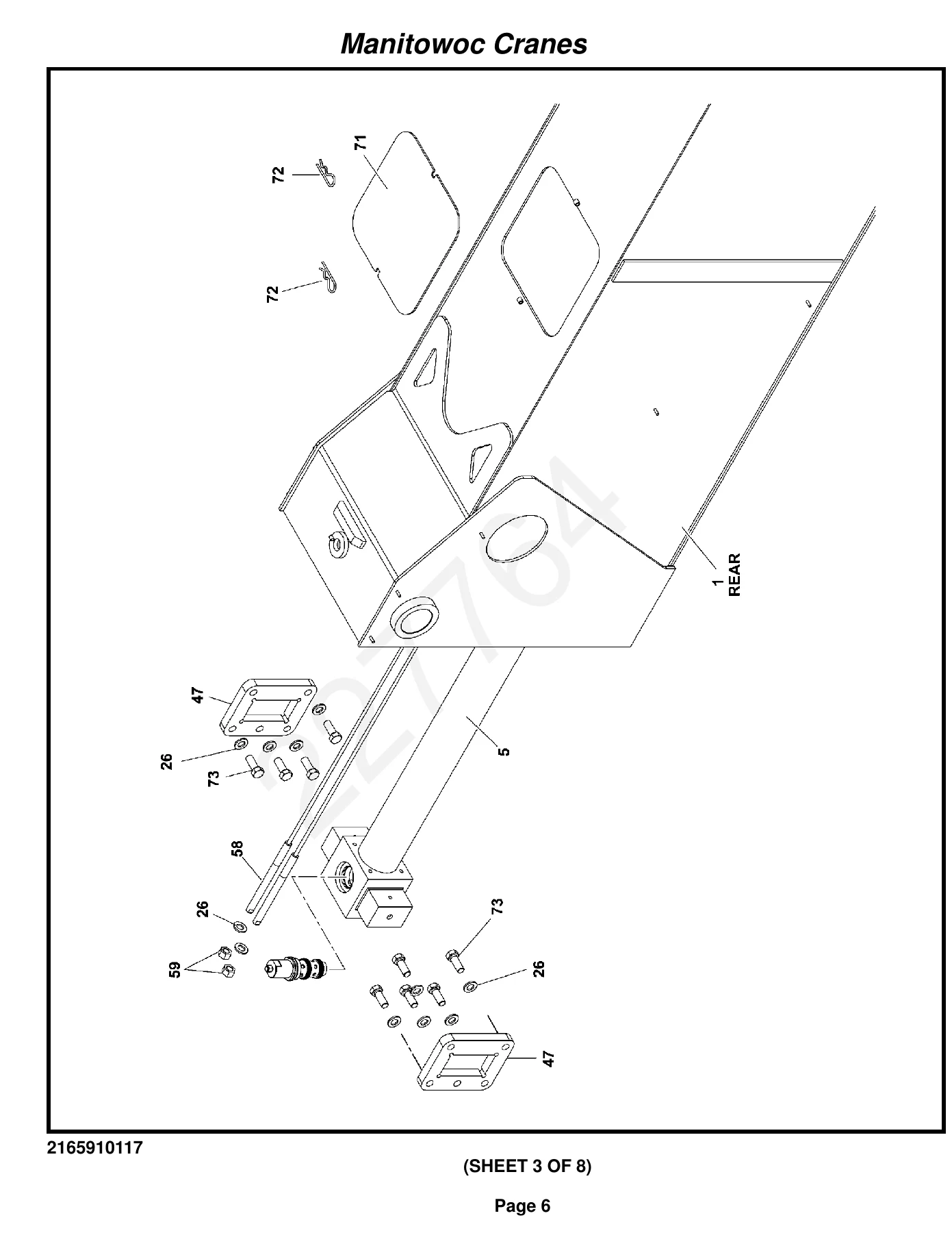
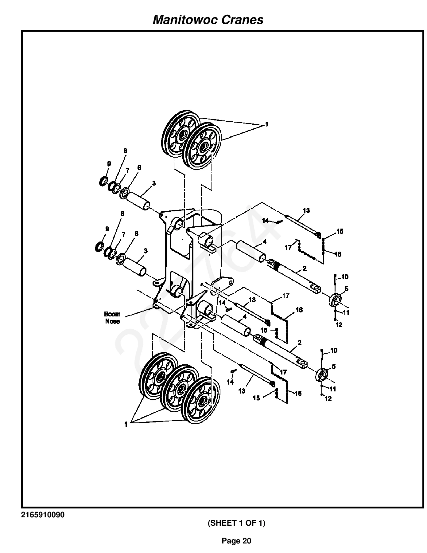
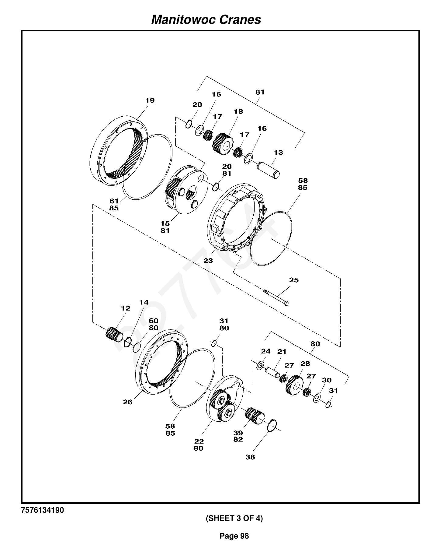
IMAGES PREVIEW
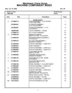
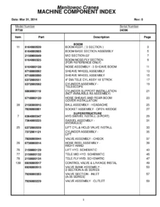
This parts manual goes far beyond a simple index. Each section provides exploded-view illustrations with itemized part numbers, descriptions, and quantities, allowing you to trace every component from the top-level assembly down to individual fasteners, seals, bearings, and fittings. Whether you are rebuilding a telescope cylinder, replacing a swing drive bearing, ordering a new sheave assembly, or tracking down a hydraulic hose for the main hoist circuit, the illustrations and parts lists in this manual give you the exact reference you need.
For the RT650E owner or fleet maintenance team, having the correct parts manual for the exact serial number is critical. Grove built the RT650E across a production range with running changes to components, part numbers, and assemblies. A manual matched to serial number 227764 ensures the part numbers you order are the ones that actually fit your machine – not a superseded or discontinued equivalent from an earlier or later build.
What This Manual Helps You Do
- Identify and order replacement parts for the boom, jib, sheaves, and hook block
- Rebuild or reseal the telescope, lift, outrigger, and steer cylinders
- Service the swing drive, turntable, and swing lock assemblies
- Trace hydraulic lines for supply, pressure, return, hoist, telescope, swing, lift, steer, and brake circuits
- Work on the Cummins QSB6.7 engine installation, cooling system, exhaust, and air cleaner
- Reference the 3-speed 12-volt transmission, drive lines, and axle assemblies
- Locate electrical components, harnesses, relays, fuses, switches, and LMI/iFlex 5 connections
- Find cab, seat, console, HVAC, and control handle part numbers
- Identify carrier frame, outrigger beam, jack cylinder, and fender/tray components
- Match decals, warning labels, and nomenclature markings
- Reference the electrical and hydraulic schematics for troubleshooting
- Use the hydraulic pressure setting procedure for system checks
Why This Manual Matters
Ordering the wrong part costs time, money, and downtime. With this Grove RT650E parts manual, you cross-reference every component against the exact assembly drawing and part number list for serial number 227764. That means fewer returns, fewer incorrect orders, and faster turnaround on repairs. The exploded views also make reassembly easier by showing how parts fit together – washers, seals, spacers, pins, and fasteners included.
The manual covers both the superstructure and the carrier in detail. On the superstructure side, you get the complete boom assembly with all four sections, the 8 1/4″ telescope cylinder, boom pivot shaft installation, sheave assemblies for the 2-over-3 and 5-groove configurations, the telescoping jib and auxiliary boom nose, the 50-ton hook block, the iFlex 5 LMI system with cable reel, roller guide, junction box, and A2B switch components, the turntable and swing drive assembly with complete gearbox breakdown, the counterweight and swing lock, the hoisting rope specification, the 10″ lift cylinder, the electric/water/hydraulic swivel assembly, the main and auxiliary hoist installation with the hoist assembly and overrun clutch, all directional control valve assemblies, the hydraulic oil accumulator, and the full hydraulic line routing for every circuit.
On the carrier side, the manual covers the carrier frame assembly, outrigger beam and jack cylinder assemblies, outrigger extension cylinders, fender and storage tray installation, decking, engine hood and cover assemblies, battery box cover, step extensions, hookblock tie-down, rear-view mirror, carrier electrical system with harness and engine relay panel, hydraulic and fuel tank installations, return filter assembly, front and rear axle installations with complete differential carrier, housing, hub and shaft, and brake group breakdowns, the Cummins drive line installation, the Cummins QSB6.7 engine assembly with all mounts, hoses, tubes, and accessories, the 3-speed 12-volt transmission with converter housing, case and cover, torque converter, gear groups, clutch packs, control valve, and output shaft groups, the radiator and cooling package, battery installation with cable kit, exhaust system, air cleaner assembly, outrigger float stowage, exterior lights and alarm, tires and wheels, and the coolant strainer installation.
The cab section covers the complete cab assembly including door installation, skylight, rear window, wiring, fan, seat and control assembly with single-axis controllers and solenoid handles, proximity switches, seat harness, acoustics installation, air conditioning installation with hydraulic A/C unit, front console panel assembly with gauges and switches, console harness and potentiometer harness, electrical system installation for the superstructure cab, 360-degree lever installation, heater/cooler installation, telescope and brake pedal installations, treadle valve assemblies, steering control valve, sun screen, transmission shifter, lock pin rod, LMI internal lightbar, electric throttle pedal, and the RT”E” series cab standard components kit.
The decal section provides complete decal installation drawings for the RT600E3 standard cab and carrier, RT600E2 standard superstructure and standard configurations, RT600E nomenclature, and miscellaneous decals. The schematics section includes the electrical schematic for RT600E3, hydraulic schematic for RT600E3, and the hydraulic pressure setting procedure.
Delivery
This Grove RT650E parts manual is delivered as an instant PDF download. No shipping, no waiting. Open it on any computer, tablet, or smartphone, search through the pages, and print only the sections you need for the job at hand. Whether you are in the shop, in the field, or at the parts counter, the manual is right there when you need it.

Reviews
There are no reviews yet.