
Grove RT9000E Crane Parts Manual 2009 – Serial 230559 PDF Download
Original price was: $39.95.$23.95Current price is: $23.95.
Complete parts manual for the Grove RT9000E crane with serial number 230559, dated January 16, 2009. Covers outriggers, boom, cab, Cummins QSC engine, transmission, axles, hydraulics, electrical systems and more with part numbers, exploded views and illustrations.
Description
Grove RT9000E Parts Manual – Serial Number 230559
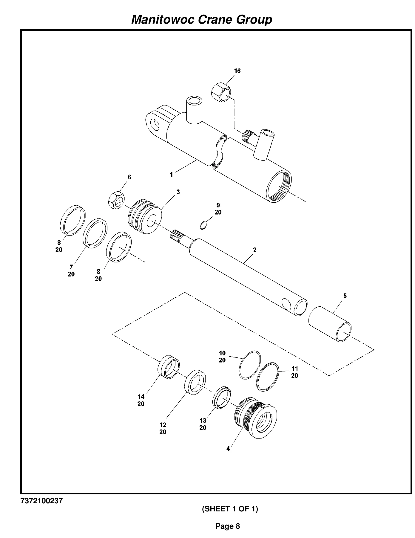
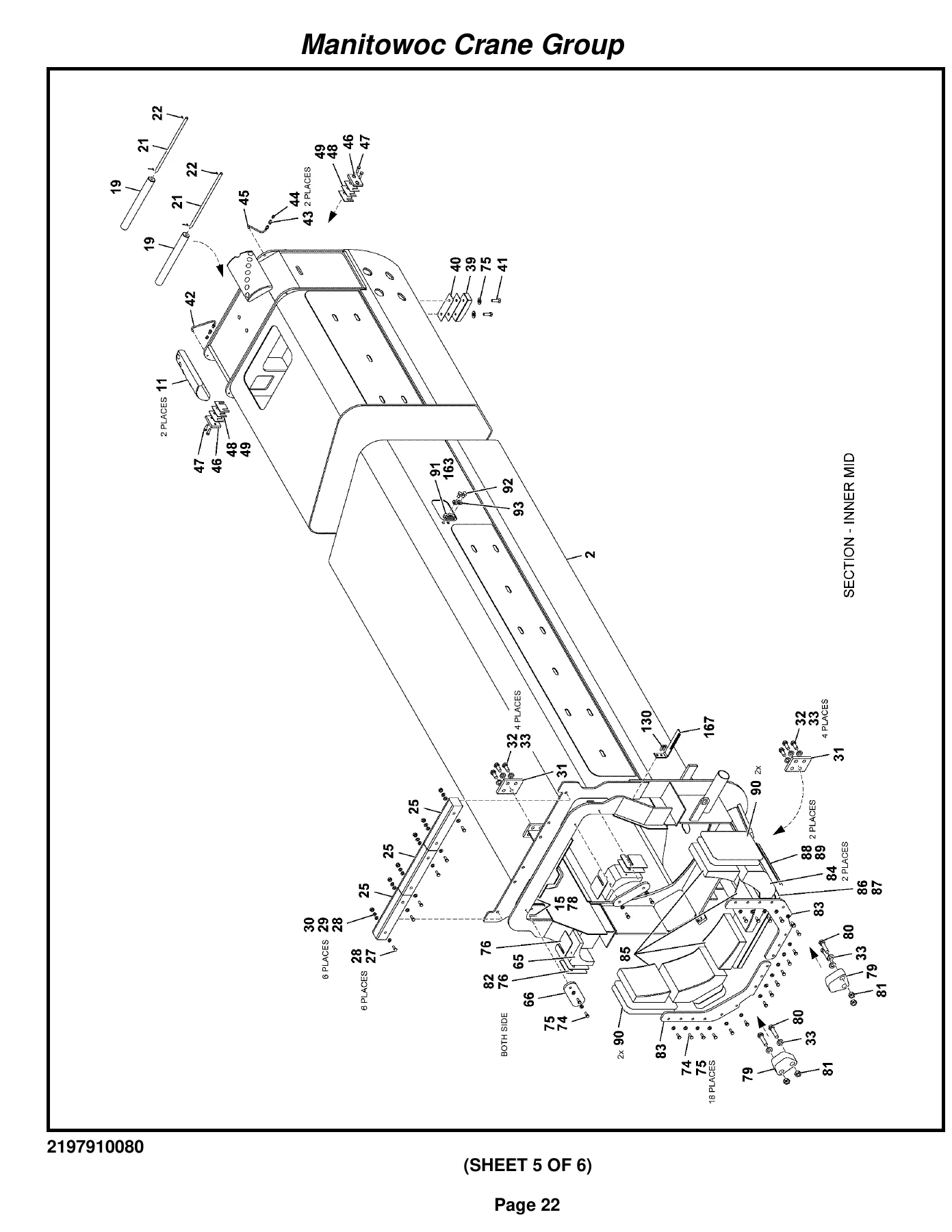
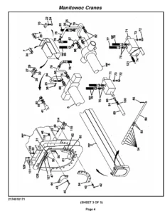
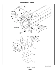
This Grove RT9000E Crane Parts Manual is the definitive illustrated parts reference for machines with serial number 230559, published on January 16, 2009. Whether you are ordering replacement components, verifying part numbers before a repair, or rebuilding a system after a failure, this manual provides the complete breakdown of every major assembly on the RT9000E. Organized by system and sub-assembly, it lists part numbers alongside descriptions and quantities, with exploded-view illustrations that show exactly how components fit together.
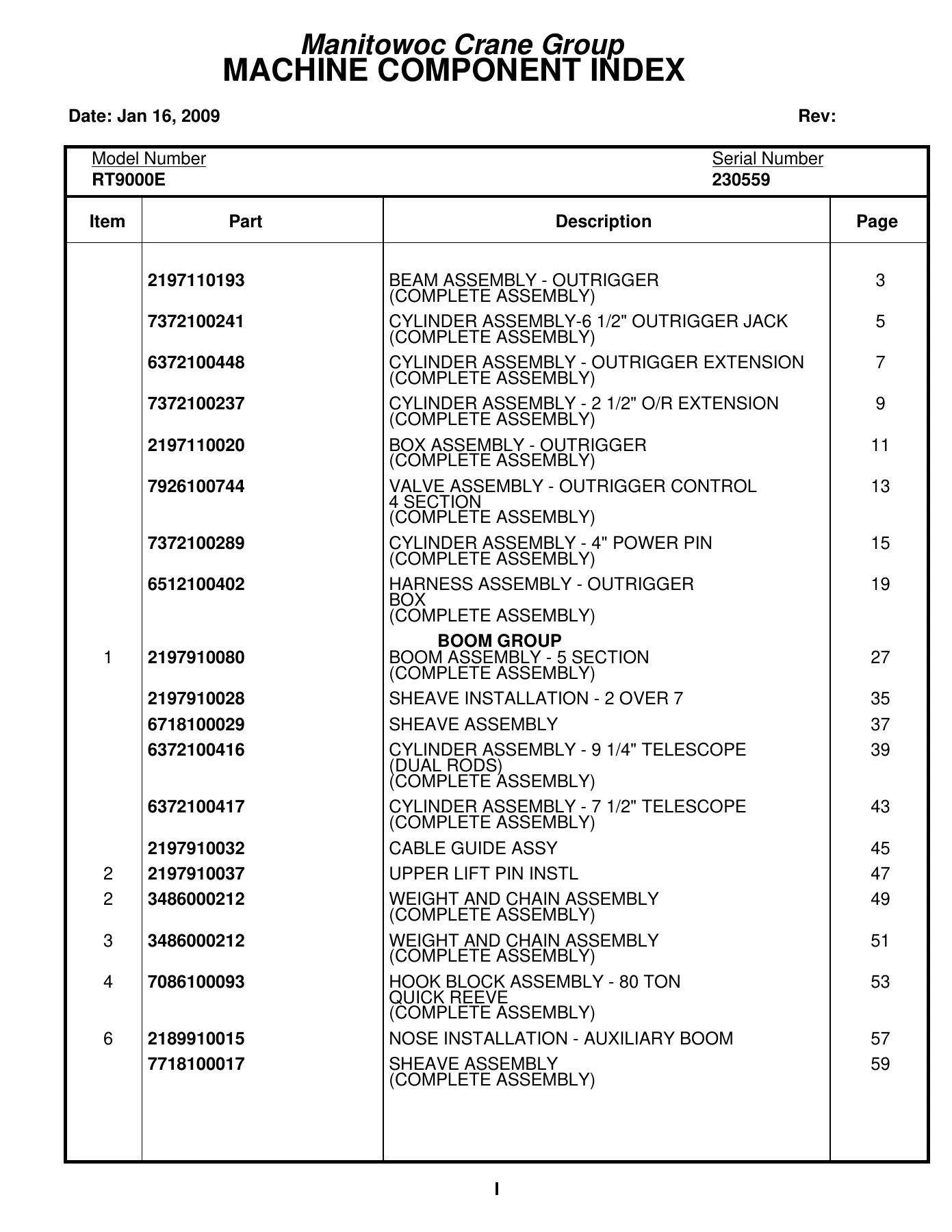
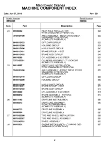
The manual opens with a master table covering all major assemblies – from the outrigger beams and jack cylinders to the five-section boom, hook block, cab group, engine installation, transmission, axles, and hydraulic valve assemblies. Each assembly is then broken down further into individual part listings with item numbers that correspond directly to the illustrations. This structure lets you trace any component from the top-level system right down to the individual seal, O-ring, or fastener.
For anyone maintaining or repairing a Grove RT9000E, having the correct parts manual is not optional – it is the difference between ordering the right part the first time and wasting days on returns, incorrect fitment, and unnecessary downtime. This PDF gives you the same parts data used by the professionals, organized in a searchable format that you can print or view on any device.
File Details
- Manual Type: Parts Manual
- Brand: Grove (Manitowoc Crane Group)
- Model: RT9000E
- Serial Number: 230559
- Date: January 16, 2009
- Language: English
- Page Count: 931
- File Format: PDF
Chapters Covered
This Grove RT9000E parts manual covers the complete machine, organized into the following major groups and assemblies:
- Outrigger System
- Beam Assembly – Outrigger (Complete Assembly)
- Cylinder Assembly – 6 1/2″ Outrigger Jack
- Cylinder Assembly – Outrigger Extension
- Cylinder Assembly – 2 1/2″ O/R Extension
- Box Assembly – Outrigger
- Valve Assembly – Outrigger Control (4 Section)
- Cylinder Assembly – 4″ Power Pin
- Harness Assembly – Outrigger Box
- Float Installation and Assembly
- O/R Hydraulic Lines – Carrier
- Boom and Lifting Equipment
- Boom Group – 5 Section Boom Assembly
- Sheave Installation – 2 Over 7
- Sheave Assembly
- Cylinder Assembly – 9 1/4″ Telescope (Dual Rods)
- Cylinder Assembly – 7 1/2″ Telescope
- Cable Guide Assembly
- Upper Lift Pin Installation
- Weight and Chain Assembly
- Hook Block Assembly – 80 Ton Quick Reeve
- Nose Installation – Auxiliary Boom Sheave Assembly
- Ball Assembly – Overhaul 10 Ton Swivel
- Socket, 3/4″ Open Wedge
- Wedge Socket Adapter Kit
- Boom Removal Kit
- Cylinder Assembly – 2″ Pin Removal
- Cab and Operator Station
- Cab Group – Cab Installation
- Cab Assembly
- Cab Weld (With Door Install)
- Door Installation – Cab
- Skylight Assembly – Sliding
- Window Assembly – Rear
- Cable Assembly
- Valve Assembly – Brake with Treadle Pedal
- Fan Assembly – 12 Volt Cab
- Acoustics Installation – RT”E” Series
- Front Console Installation
- Console Assembly – Front
- Panel Assembly – Front Console
- Harness Assembly – Front Console
- Harness Assembly – Potentiometer
- Electrical System Installation – Superstructure Cab
- 360 Lever Installation
- Air Conditioning and Heater Installation (Cab)
- Kit – Cab Heater and Air Conditioner
- Pedal Installation – Telescope
- Valve Assembly – Treadle (Telescope)
- Screen Installation – Sun
- Binder Installation
- Cab Tilt Installation
- Cylinder Assembly – 2 1/2″ Steer
- Cover Installation – Cab Rear
- Air Conditioning Installation – Superstructure
- Kit – Hydraulic Air Conditioner Unit 12 Volt
- Pedal Installation – Brake
- Shifter Installation – Transmission
- Steer Valve Installation
- Steering Control Valve
- Pedal Installation – Throttle (Electric)
- Switch Installation – Air Conditioner
- Lines Installation – Air Conditioning (Cab)
- Kit – Air Conditioner Hose
- Pole Installation – Jib Release
- Hydraulic Control Systems
- Control Valve Group – Upper Valve Installation
- Valve Assembly – Control
- Valve Assembly – Counterweight
- Valve Assembly – Selector
- Valve Assembly – Pressure Reducing Sequence
- Valve Assembly – Directional Control
- Accumulator Assembly – Hydraulic Oil
- Valve Assembly – Dual Pilot Operated Check
- Valve – Manual Bleed Off Pressure
- Hydraulic Lines Installation – Supply, Pressure and Return (With Air Conditioning)
- Lift Hydraulic Lines Installation – Superstructure
- Hydraulic Lines Installation – Main and Auxiliary Hoist
- Cylinder Installation – Lift
- Cylinder Assembly – 14″ Lift
- Hydraulic Lines Installation – Telescope (Superstructure)
- Switch Assembly – Pressure (Modified)
- Valve Assembly – Solenoid
- Valve Assembly – Shuttle
- Swing Hydraulic Lines Installation – Superstructure
- Valve Assembly – Residual Check
- LMI Hydraulic Lines Installation – Superstructure
- Hydraulic Lines Installation – Counterweight Removal (With Luffing Jib)
- Hydraulic Lines Installation – Telescope (Cab)
- Swing and Swing Brake Hydraulic Lines Installation
- Main and Auxiliary Hoist Hydraulic Lines Installation
- Lift Hydraulic Lines Installation – Cab
- Steer Hydraulic Lines Installation – Cab
- Brake Hydraulic Lines Installation – Cab
- Lines Installation – Motor Case Drain Air Conditioner
- Hydraulic Reservoir Installation
- Hydraulic Reservoir Assembly
- Hydraulic Reservoir
- Filter Assembly
- Valve Installation – Hydraulic Without Differential Lock (Carrier)
- Valve Assembly – Integrated Outrigger/Rear Steer
- Valve Assembly – Axle Disconnect and Park Brake
- Valve Assembly – Solenoid
- Switch Assembly – Pressure (Normally Closed)
- Valve – Manual Bleed Off Pressure
- Valve Assembly – Double Solenoid
- Hoist and Turntable
- Hoist Group – 19mm Hoisting Rope 35X7X214M
- Counterweight Installation – 24000 LB
- Cylinder Assembly – 4″ Counterweight Removal
- Hoist Installation – Main and Auxiliary
- Cylinder Assembly – 3″ Hoist Pin Removal
- Indicator Installation – Hoist Rotation
- Control Assembly – Hoist Rotation Indicator
- Turntable Group – Swivel Installation – Electric, Water and Hydraulic
- Swivel Assembly – Electric, Water and Hydraulic
- Swivel Assembly – 11 Port Hydraulic
- Swivel Assembly – 2 Port Water
- Ring Assembly – Slip 15 Conductor
- Lever Installation – Counterweight Removal
- Bolt Installation – Bearing
- Heavy Counterweight Installation
- Pin Assembly
- Valve Cover Installation
- Lock Pin Installation – Turntable
- Hose Retainer Installation
- Lock Installation – Swing 360 Degree
- Lock Assembly – Swing
- Engine and Power Train
- Engine Group – Hood Installation
- Front Sub Assembly – Hood
- Engine Installation – Cummins QSC (With Air Conditioning)
- Engine Assembly – Cummins QSC (With Air Conditioning)
- Converter Assembly – Torque
- Torque Convertor Group
- Charge Pump and Regulating Valve Group
- Pump Assembly
- Dual Pump Disconnect Group
- Pump Assembly – 2 Section Gear
- Pump Assembly – Gear with Flow Control
- Hydraulic Lines Installation – Engine (Carrier)
- Electrical System Installation – Engine
- Kit – Cable (Engine)
- Transmission Installation
- Transmission Assembly
- Input Shaft and Cover Group
- Case and Rear Cover Group
- Drive Group – Low Speed
- Forward Clutch and Shaft Group
- Shaft Group – Reverse and Second
- Shaft Group – First Clutch
- Idler Group – Forward High
- Shaft Group – Forward High and Third
- Idler Shaft Group
- Shaft Group – Output
- Control Valve Mounting Group
- Valve Assembly – Control
- Flange Group
- Radiator Installation
- Radiator Assembly
- Cooler Assembly – Radiator/Charge Air
- Tank Assembly – Surge
- System Installation – Exhaust
- Cleaner Installation – Air
- Cleaner Assembly – Air
- Strainer Installation – Coolant
- Disconnect Installation – Pump
- Heater Installation – Block
- Drive Train Group
- Trans Filter/Lines Installation
- Filter Assembly
- Axles and Drive
- Axle Group
- Front Steer Hydraulic Lines Installation – Carrier
- Axle Installation – Rear Standard Differential
- Axle Assembly – Rear Drive Steer Standard Differential
- Differential Carrier Group
- Housing Group
- Hub and Shaft Group
- Brake Group, 4 Set
- Brake Assembly Group
- Cylinder Assembly – 7″ Lockout
- Switch Assembly – Proximity (Normally Open)
- Axle Installation – Front Standard Differential
- Axle Assembly – Front Drive Steer Standard Differential
- Cylinder Assembly – 3 1/2″ Steer
- Brake Assembly – Parking
- Tire and Wheel Installation
- Tire and Wheel Assembly
- Wheel Assembly
- Rear Steer Hydraulic Lines Installation – Carrier
- Frame and Carrier
- Frame Group – Fender Installation
- Exterior Lights and Alarm Installation
- Hookblock Tie-Down Installation
- Cover Installation – Battery Box
- Mirror Installation – Rear View
- Stand Installation – Counterweight
- Cooler Installation – Hydraulic and Transmission Oil
- Cooler Assembly – Hydraulic and Transmission Oil
- Hardware Kit – Decal
- Lift Cylinder Travel Support Installation
- Lift Cylinder Travel Support Assembly
- Bottle Jack (Modified)
- Cylinder Assembly – Bottle Jack
- Tank Installation – Fuel
- Tank Assembly – Fuel 100 Gallon
- Mounting Kit – Oil Cooler
- Battery Installation
- Cable Kit – RT9000E Batteries
- Electrical System Installation – Carrier
- Harness Assembly – Carrier
- Panel Assembly – Engine Relays
- Harness Assembly – Engine Relay Panel
- Box Assembly – Outrigger Pin Controls
- Cable Assembly – LH Remote O/R Remote
- Hydraulic Lines Installation – Carrier Supply, Pressure and Return
- Valve Assembly – Solenoid
- Solenoid Valve 2 Way N.O.
- Hydraulic Lines Installation – Rear Axle Lockout (Carrier)
- LMI and Safety Systems
- LMI Boom Kit – iFlex 5 (BCS)
- Cable Reel Assembly – iFLEX 5 176′
- Cable Reel Assembly – iFLEX 5 87′
- Slipring Assembly – 11 Conductor
- Flag Assembly – A2B Retainer
- LMI Boom Kit Installation – iFlex5 BCS
- Kit Installation – LMI System (Superstructure)
- LMI Aux Nose Kit
- Kit Installation – Auxiliary Nose LMI
- Kit – LMI Wireless Anemometer
- Kit Installation – LMI Wireless Anemometer
- LMI Internal Light Bar Installation
- ESI – Superstructure
- HA – Superstructure
- Switch Assembly – Proximity (Normally Open)
- Kit – LMI iFLEX 5 Cab (For BCS Machines)
- Central Unit – iFLEX 5
- Graphic Console (Version) – iFLEX5
- Kit Installation – iFLEX5 LMI Cab
- Indexes and Reference
- Alphabetical Index
- Numerical Index
- Recommended Spare Parts List
- Belt and Filter Maintenance List
- Foot Note Index
With over 900 pages of part numbers, illustrations, and exploded views, this Grove RT9000E parts manual gives you the complete picture of the machine’s construction. Every major assembly is broken down into its individual components with part numbers you can use to order replacements, verify fitment, or cross-reference during a rebuild. The alphabetical and numerical indexes at the end of the manual let you look up any part number and find exactly where it is used, which is invaluable when you have a part in hand and need to know what it belongs to.
The manual also includes a recommended spare parts list organized by year of service, and a belt and filter maintenance list that tells you what to replace and when. For a crane of this size and complexity, that kind of structured maintenance information is essential for keeping the machine in service and avoiding unexpected failures.
What This Parts Manual Enables You to Do
This is not a general guide or a simplified overview – it is the complete parts breakdown for the Grove RT9000E with serial number 230559. With this manual, you can:
- Identify and order the correct part number for any component on the crane, from the largest assembly down to individual seals, O-rings, and fasteners
- Verify that a part is correct for your specific machine before you buy it, eliminating the cost and delay of returns and incorrect fitment
- Trace components through the exploded-view illustrations to understand how systems assemble and disassemble
- Use the alphabetical and numerical indexes to look up any part number and find exactly where it is used
- Reference the recommended spare parts list to plan maintenance and stock critical components
- Follow the belt and filter maintenance schedule to keep the Cummins QSC engine and hydraulic systems running reliably
For a crane like the RT9000E, using the wrong part or guessing at a component can lead to costly damage, safety issues, and extended downtime. The correct parts manual is the foundation of any professional repair or maintenance program. This PDF gives you that information in a convenient, printable format that you can keep on your computer, tablet, or phone, or print out the pages you need for the job.
IMAGES PREVIEW
After purchase, the manual is delivered instantly as a downloadable PDF – no shipping, no waiting, no physical book to lose. You can view it on any device, search through the pages, and print only the sections you need. Whether you are a crane owner, fleet maintenance manager, or field technician, having the Grove RT9000E parts manual for serial number 230559 on hand means you can tackle any repair with confidence and get the right parts the first time.
Reviews
There are no reviews yet.