★ TRUSTED BY 321,897+ PROFESSIONALS WORLDWIDE
🏢
Trusted Business
Verified & Licensed
🛡️
Virus Free Files
100% Safe Downloads
🔒
Secure Payment
SSL Protected
⚡
Instant Delivery
Available Immediately
Sale!

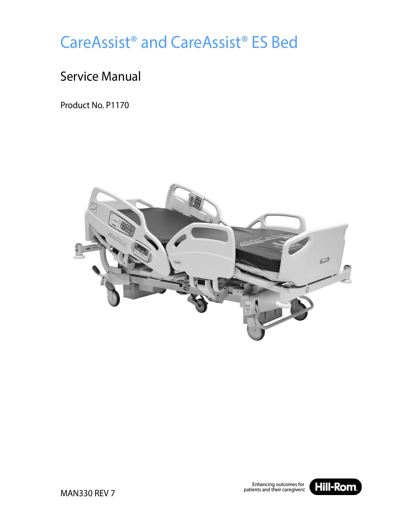
Hill-Rom CareAssist & CareAssist ES Bed Service Manual (MAN330 Rev 7) – P1170A Through P1170G

Original price was: $39.95.Current price is: $22.95.

Complete seventh-edition Hill-Rom service manual for the CareAssist and CareAssist ES beds, product number P1170. Covers troubleshooting RAPs, theory of operation, component replacement procedures, parts lists, preventive maintenance, and full fold-out wiring schematics in one 379-page PDF.

⚡
Instant PDF Download
Available immediately
💾
Save to Your Device
Download & keep forever
🛡️
Antivirus Scanned
100% virus-free
🌍
Trusted Worldwide
175,000+ customers

Description

This Hill-Rom CareAssist and CareAssist ES Bed Service Manual (MAN330 Rev 7) is the seventh-edition service documentation for the P1170 series of CareAssist and CareAssist ES beds. Inside you get troubleshooting repair analysis procedures, theory of operation, step-by-step component replacement procedures, illustrated parts lists, cleaning and preventive maintenance schedules, and the complete set of fold-out schematics. It is written for facility-authorized service personnel and trained users who maintain these beds in a clinical environment.

File Details

  • Manual type: Service Manual
  • Brand: Hill-Rom
  • Product number: P1170
  • Document number: MAN330
  • Edition: Seventh Edition, March 2017 (first printing 2003)
  • Language: English
  • Page count: 379 pages
  • File format: PDF
  • Reference documents: CareAssist Bed and CareAssist ES Bed User Manual (USR116); CareAssist Bed Unpacking Instructions (IS869)

Chapters Covered

  • Chapter 1: Introduction
    • Purpose, Audience, and Reference Documents
    • Document Symbols
    • Specifications (dimensions, environmental conditions, electrical, fuses, auxiliary outlet)
    • Nurse Call Connection Requirements
    • Regulation, Standards, and Codes
    • Electromagnetic Emissions and Immunity Guidance
    • Model Identification
    • Safety Tips and Warning/Caution Labels
  • Chapter 2: Troubleshooting
    • Initial Actions and Problem/Solution Tables
    • Function Checks and Scale and Bed Exit Function Check
    • RAP 2.1 No Functions Work through RAP 2.12 Steering Malfunction
    • Scale Error 0 through Scale Error 5 (B model beds and C model and newer beds)
    • Service Required LED Flashes and Siderail Detection Switch Malfunction
    • IntelliDrive Transport System diagnostics: battery check, steer switch check, PACM board power/deployment/drive checks, motor check, handle enable switch check, throttle check, handle gauge checks, controller check, junction board debugging
  • Chapter 3: Theory of Operation
    • Mechanical System: retractable head section, emergency CPR release, extendable foot section, hilow system, casters, braking, steering, head and footboards
    • Electrical System (A model beds): power supply characteristics, power stage, function control, battery circuit, control logic, patient pendant, motor management
    • Electrical System (B model and newer beds): power stage, function control, battery circuit, control logic
    • Scale and Bed Exit Systems (B model beds; C model and newer beds)
    • Electrical System Wiring Diagrams
  • Chapter 4: Procedures
    • Tool and Supply Requirements, Component Handling, P.C. Board
    • Sleep Deck; AC Power Cord and Power Cord; Power Supply; Batteries
    • Head Section Motor, CPR Cable, Knee Section Motor, Foot Section Motor
    • Head Hilow Column and Foot Hilow Column
    • Brake Detection Switch, Brake/Steer Bar, Caster
    • SideCom Communication System P.C. Board, Interface P.C. Board, Siderail Interface P.C. Board
    • Fuses, Siderail Control P.C. Board, Patient Pendant, Patient Pendant Mount
    • Bed Exit Switch, Load Beams, Scale Control Pod, Scale Control Pod P.C. Board, Scale Calibration
    • Motor Control P.C. Board, Line Filter, Scale P.C. Board, Transformer
    • Fifth Wheel, Head-End Brake/Steer Pedal, Auxiliary Outlet, SafeView Alerts
    • IntelliDrive Transport Handles, IntelliDrive Batteries, IntelliDrive Interface P.C. Board, IntelliDrive PACM Board, IntelliDrive Motor Controller, IntelliDrive Drive Box, Drive Motor, Drive Unit
    • Traction Frame Support Module, Infusion Support System, Oxygen Tank Holder, IV Pole, Mattress Pad Extender, Mattress
  • Chapter 5: Parts List
    • Service Parts Ordering and Exchange Policy
    • Recommended Spare Parts
    • Base Frame, Articulating Frame, Foot Extension
    • Head Siderail, Head Siderail Mounting, Foot Siderail
    • Footboard and Headboard, Plastic Sleep Deck, CPR Cables
    • Motor Control Box, Control Cables, Interface Control Box
    • Auxiliary Outlet, SafeView Alerts, 5th Wheel, IntelliDrive Transport System
  • Chapter 6: Cleaning and Preventive Maintenance
    • Clean and Disinfect
    • Lubrication Requirements
    • Preventive Maintenance and Specified Checks
    • Preventive Maintenance Checklist
  • Schematics: SideCom Communication System (A through E and F model beds), Siderail Interface P.C. Board variants, Caregiver Control and Signal Conditioning, Bed Control Board power, phase, battery, clock, relay/FET and PLD diagrams, motor current limiter, bed wiring schematics by model, and IntelliDrive Transport System wiring.

Read as a whole, the manual gives a technician a complete service loop: identify the bed model, work the symptom through the troubleshooting flow charts, confirm the theory behind the fault, then follow the matching disassembly and replacement procedure and finish with the function checks and preventive maintenance schedule. Because the same document carries the parts lists and fold-out schematics, you are not left hunting a second source for a connector number or a replacement part.

Complete PDF Bookmark Tree

Complete Bookmarks

The complete bookmarks in the “Hill-Rom CareAssist & CareAssist ES Bed Service Manual (MAN330 Rev 7) – P1170A Through P1170G” are as follows:

Table of Contentsp. 5
Chapter 1 Introductionp. 15
Purposep. 15
Audiencep. 15
Reference Documentsp. 15
(Specifications)p. 15
Document Symbolsp. 16
Specificationsp. 16
Physical Descriptionp. 16
Table 1-1. Dimensionsp. 16
Table 1-2. Specificationsp. 17
Table 1-3. Environmental Conditions for Transport and Storagep. 17
Nurse Call Connection Requirementsp. 17
Table 1-4. Environmental Conditions for Usep. 17
Electrical Specificationp. 17
Table 1-5. AC Power Requirementsp. 17
Table 1-6. Auxiliary Outlet Power Specifications (120 V Beds Only) (Beds with the Optional Auxiliary Outlet)p. 18
Table 1-7. Fuse Specificationsp. 18
Regulation, Standards, and Codesp. 18
Table 1-8. Regulation, Standards, and Codesp. 18
Electromagnetic Emissions and Immunity Guidancep. 19
Table 1-9. Electromagnetic Emissions Guidancep. 19
Table 1-10. Electromagnetic Immunity Guidancep. 20
Model Identificationp. 21
Table 1-11. Model Identificationp. 21
Safety Tipsp. 21
Beds with an Auxiliary Outletp. 22
Warning and Caution Labels (Sheet 1 of 2)p. 23
Figure 1-1. Warning and Caution Labelsp. 23
Warning and Caution Labels (Sheet 2 of 2)p. 24
Chapter 2 Troubleshootingp. 25
Getting Startedp. 25
Initial Actionsp. 25
Problem/Solution Tablep. 26
Table 2-1. Problem/Solution Tablep. 26
Table 2-2. Scale Display Errors—B Model Bedsp. 26
Table 2-3. Scale Display Errors—C and Newer Model Bedsp. 26
Table 2-4. SafeView® Alertsp. 27
Table 2-5. IntelliDrive® Transport Systemp. 28
Function Checksp. 29
Scale and Bed Exit Function Checkp. 32
Final Actionsp. 33
2.1 No Functions Workp. 34
2.2 Lockout Malfunctionp. 36
2.3 Hilow Malfunctionp. 37
2.4 Knee Section Malfunctionp. 38
2.5 Head Section Malfunction (excluding Automatic Contour)p. 39
2.6 Battery Backup Malfunctionp. 40
2.7 Foot Section Malfunctionp. 41
Figure 2-1. 4-pin Connectorp. 41
2.8 Trendelenburg/Reverse Trendelenburg Malfunctionp. 43
2.9 Bed Connected to AC Power, Brakes Not Applied Detection Malfunctionp. 44
Figure 2-2. 8-pin connectorp. 44
2.10 CPR Malfunctionp. 46
2.11 Braking Malfunctionp. 47
2.12 Steering Malfunctionp. 48
2.13 Scale Error 0—B Model Bedsp. 49
2.14 Scale Error 1—B Model Bedsp. 50
2.15 Scale Error 2—B Model Bedsp. 51
2.16 Scale Error 3—B Model Bedsp. 52
2.17 Scale Error 5—B Model Bedsp. 53
2.18 Scale Error 0—C Model and Newer Bedsp. 54
2.19 Scale Error 1—C Model and Newer Bedsp. 55
2.20 Scale Error 2—C Model and Newer Bedsp. 56
2.21 Scale Error 3—C Model and Newer Bedsp. 57
2.22 Scale Error 4—C Model and Newer Bedsp. 58
2.23 Scale Error 5—C Model and Newer Bedsp. 59
2.24 Service Required LED Flashes—C Model and Newer Bedsp. 60
2.25 Siderail Detection Switch Malfunction—F Model and Newer Bedsp. 61
2.26 Bed Will Not Drivep. 62
2.27 Bed Will Not Drive, Wheel is Downp. 63
2.28 Wheel Will Not Stowp. 64
2.29 Battery Checkp. 65
2.30 Steer Switch Checkp. 66
2.31 PACM Board Power Checkp. 67
2.32 PACM Board Deployment Checkp. 68
2.33 PACM Board Drive Checkp. 69
2.34 Motor Checkp. 70
2.35 PACM to Junction Board Cable Checkp. 71
2.36 Handle Enable Switch Checkp. 72
2.37 Throttle Checkp. 73
2.38 Handle Gauge Check (Sheet 1 of 3)p. 74
2.39 Handle Gauge Check (Sheet 2 of 3)p. 75
2.40 Handle Gauge Check (Sheet 3 of 3)p. 76
2.41 Controller Check—IntelliDrive® Transport Systemp. 77
Table 2-6. Controller Error Codesp. 77
2.42 Visual Inspection—IntelliDrive® Transport Systemp. 79
2.43 Junction Board Debugging—IntelliDrive® Transport Systemp. 80
Enable Switchesp. 80
Throttle Debuggingp. 81
Chapter 3 Theory of Operationp. 83
Introductionp. 83
Mechanical Systemp. 83
Retractable Head Sectionp. 83
Emergency CPR Releasep. 83
Extendable Foot Sectionp. 83
Hilow Systemp. 84
Castersp. 84
Brakingp. 84
Steeringp. 84
Head and Footboardsp. 84
Electrical System (A Model Beds)p. 85
Table 3-1. Specificationsp. 85
Power Supply Unit Characteristicsp. 85
Table 3-2. Power Supply Unit Characteristicsp. 85
Power Stagep. 86
Function Controlp. 86
Battery Circuitp. 86
Battery Characteristicsp. 87
Table 3-3. Battery Backup Characteristicsp. 87
Control Logic and Specific Functionsp. 87
Patient Pendantp. 88
Motor Characteristicsp. 88
Table 3-4. Motor Characteristics and Dimensionsp. 88
Management of the Motorsp. 88
Detection of Bed Not in Low Positionp. 88
Automatic Contourp. 89
Dining Chair® Positionp. 89
Detection of Bed Connected to AC Power but Brakes Not Setp. 89
Trendelenburg/Reverse Trendelenburgp. 89
Electrical System (B Model and Newer Beds)p. 90
Table 3-5. Specificationsp. 90
Table 3-6. Voltage and Frequencyp. 90
Power Supply Unit Characteristicsp. 90
Table 3-7. Power Supply Unit Characteristicsp. 90
Table 3-8. Maximum Power Loadp. 91
Power Stagep. 91
Function Controlp. 92
Battery Circuitp. 92
Battery Characteristicsp. 92
Table 3-9. Battery Backup Characteristicsp. 92
Control Logic and Specific Functionsp. 93
Patient Pendantp. 93
Motor Characteristicsp. 93
Table 3-10. Motor Characteristics and Dimensionsp. 93
Management of the Motorsp. 94
Detection of Bed Not in Low Positionp. 94
Automatic Contourp. 94
Dining Chair® Positionp. 94
Detection of Bed Connected to AC Power but Brakes Not Setp. 94
Trendelenburg/Reverse Trendelenburgp. 94
Scale and Bed Exit Systems—B Model Bedsp. 95
Scale and Bed Exit Alarm System—C Model and Newer Bedsp. 95
Electrical System Wiring Diagramp. 98
Figure 3-1. SideCom® Communication System (A through E Model Beds)p. 98
Figure 3-2. Siderail Interface P.C. Board—P/N 72207 and 71514 (Beds without the SafeView® Alerts or the NaviCare® Patient Safety Module)p. 98
Figure 3-3. Caregiver Controlp. 98
Figure 3-4. Caregiver Signal Conditioningp. 98
Figure 3-5. Bed Control Board Power and Phase Controlp. 98
Figure 3-6. Bed Control Board Power Managementp. 98
Figure 3-7. Bed Control Board Battery Managementp. 98
Figure 3-8. Bed Control Board Clock and Dividerp. 98
Figure 3-9. Bed Control Board Relay, FET and Driversp. 98
Figure 3-10. Bed Control Board PLD and Connectorp. 98
Figure 3-11. Bed Control Board Motor Current Limiter (A, B and C Model Beds)p. 98
Figure 3-12. Bed Wiring Schematic (A Model Beds)p. 98
Figure 3-13. Bed Wiring Schematic (B Model Beds)p. 98
Figure 3-14. Bed Wiring Schematic (C Model and Newer Beds without the SafeView® Alerts or the NaviCare® Patient Safety Module)p. 99
Figure 3-15. Bed Control Board Motor Current Limiter (D Model and Newer Beds)p. 99
Figure 3-16. SideCom® Communication System (F Model Beds)p. 99
Figure 3-17. Siderail Interface P.C. Board (Beds with the SafeView® Alerts or the NaviCare® Patient Safety Module)p. 99
Figure 3-18. Bed Wiring Schematic (Beds with the SafeView® Alerts or the NaviCare® Patient Safety Module)p. 99
Figure 3-19. Wiring Schematic IntelliDrive® Transport Systemp. 99
Figure 3-20. IntelliDrive® Transport System Power Supplyp. 100
Chapter 4 Proceduresp. 101
Tool and Supply Requirementsp. 101
Component Handlingp. 102
P.C. Boardp. 102
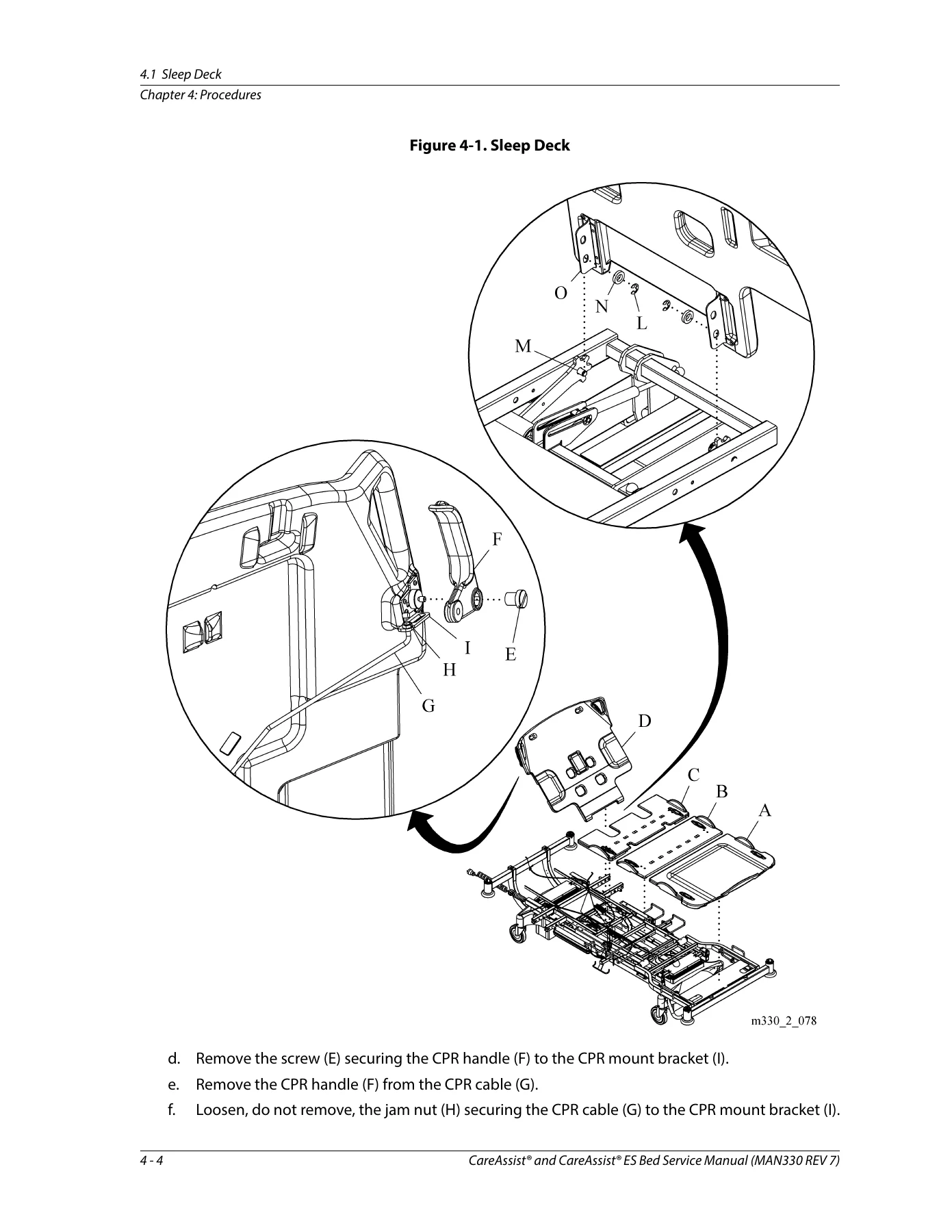
4.1 Sleep Deckp. 103
Figure 4-1. Sleep Deckp. 104
4.2 AC Power Cord (A Model Beds)p. 106
Figure 4-2. Power Cordp. 107
4.3 Power Cord (B Model and Newer Beds)p. 108
Figure 4-3. Power Cordp. 109
4.4 Power Supply (A Model Beds)p. 110
Figure 4-4. Power Supplyp. 110
Figure 4-5. Cable Routingp. 111
Table 4-1. Power Supply Connectionsp. 111
4.5 Battery (A Model Beds)p. 113
Figure 4-6. Batteryp. 113
4.6 Batteries (B Model and Newer Beds)p. 115
Figure 4-7. Batteriesp. 115
4.7 Head Section Motorp. 116
Figure 4-8. Power Supplyp. 116
Figure 4-9. B Model Bedsp. 117
Figure 4-10. Head Motorp. 118
4.8 CPR Cablep. 119
Figure 4-11. CPR Cablep. 119
Figure 4-12. CPR Cable Adjustmentp. 120
Adjustmentp. 120
4.9 Knee Section Motorp. 122
Figure 4-13. Power Supplyp. 122
Figure 4-14. B Model Bedsp. 123
Figure 4-15. Knee Motorp. 124
4.10 Foot Section Motorp. 125
Figure 4-16. Power Supplyp. 125
Figure 4-17. B Model Bedsp. 126
Figure 4-18. Foot Motorp. 127
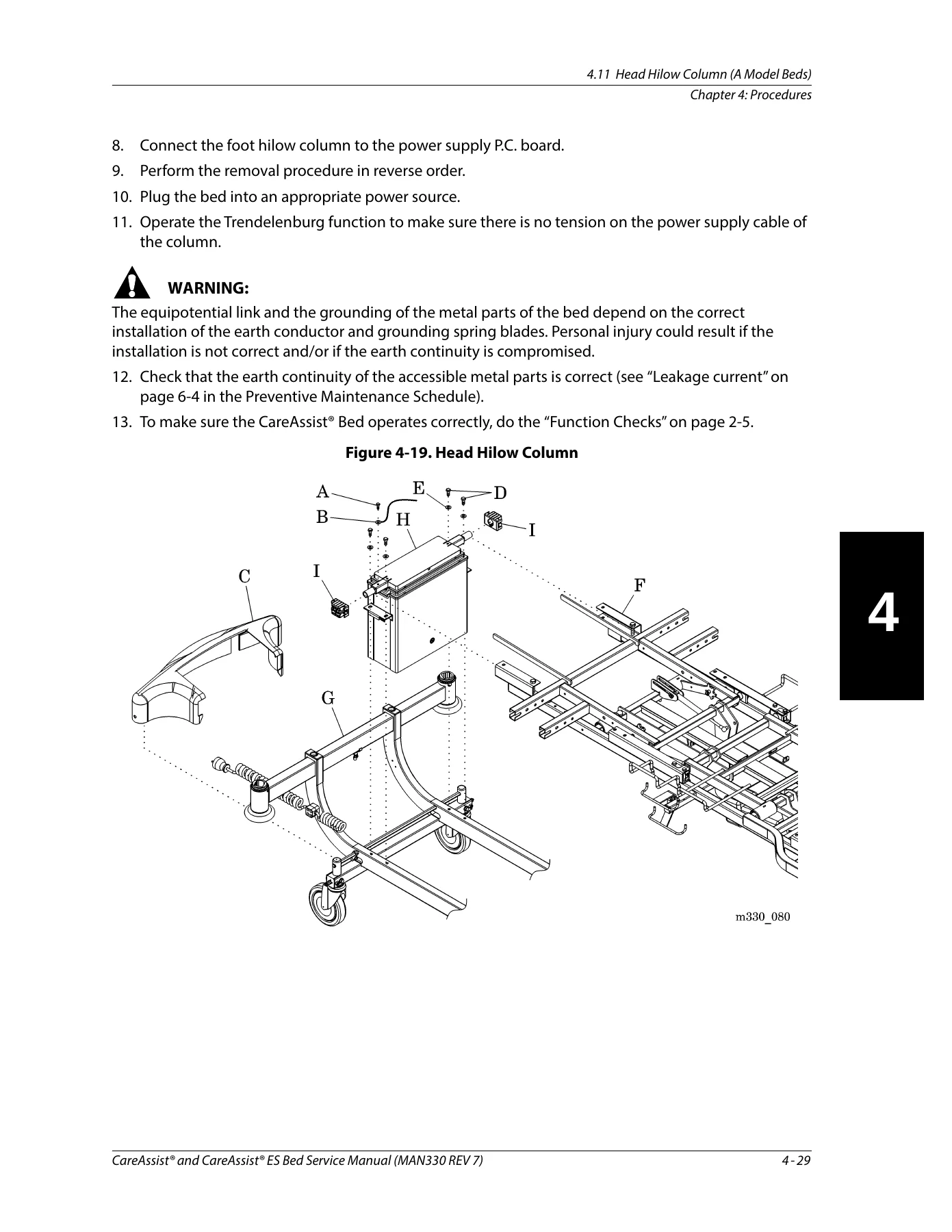
4.11 Head Hilow Column (A Model Beds)p. 128
Figure 4-19. Head Hilow Columnp. 129
4.12 Head Hilow Column (B Model and Newer Beds)p. 130
Figure 4-20. Power Supply Coverp. 131
Figure 4-21. Head Hilow Columnp. 132
4.13 Foot Hilow Column (A Model Beds)p. 134
Figure 4-22. Foot Hilow Columnp. 135
4.14 Foot Hilow Column (B Model and Newer Beds)p. 137
Figure 4-23. Power Supply Coverp. 138
Figure 4-24. Foot Hilow Columnp. 139
4.15 Brake Detection Switchp. 141
Figure 4-25. Brake Detection Switchp. 142
4.16 Brake/Steer Barp. 143
Figure 4-26. Brake Barp. 144
4.17 Casterp. 146
Figure 4-27. Casterp. 147
4.18 SideCom® Communication System P.C. Board (A Model Beds)p. 148
Figure 4-28. SideCom® Communication System P.C. Boardp. 149
4.19 SideCom® Communication System P.C. Board (B Model and Newer Beds)p. 150
Figure 4-29. Communication P.C. Boardp. 151
4.20 Interface P.C. Board (A Model Beds)p. 152
Figure 4-30. Interface P.C. Boardp. 152
4.21 Siderail Interface P.C. Board (B Model and Newer Beds)p. 154
Figure 4-31. Interface P.C. Boardp. 155
4.22 Fuses (A Model Beds)p. 156
Figure 4-32. Fusesp. 157
4.23 Fuses (B Model and Newer Beds)p. 158
Figure 4-33. Power Supply Coverp. 159
Figure 4-34. Fusesp. 160
4.24 Siderail Control P.C. Boardp. 161
Figure 4-35. Siderail Control P.C. Boardp. 162
4.25 Patient Pendantp. 163
4.26 Patient Pendant Mountp. 164
4.27 Bed Exit Switchp. 165
Figure 4-36. Bed Exit Switchp. 166
Figure 4-37. B Model Bedsp. 167
4.28 Load Beams (B Model and Newer Beds)p. 169
Figure 4-38. Load Beamsp. 170
4.29 Scale Control Pod (B Model and Newer Beds)p. 172
Figure 4-39. Control Podp. 173
4.30 Scale Control Pod P.C. Board (B Model and Newer Beds)p. 174
Figure 4-40. P.C. Board Replacementp. 175
4.31 Scale Calibrationp. 176
Figure 4-41. Scale Calibration Switchp. 177
Figure 4-42. Calibration Weight Positionp. 178
4.32 Motor Control P.C. Board (B Model and Newer Beds)p. 180
Figure 4-43. Motor Control P.C. Boardp. 181
4.33 Line Filter (B Model and Newer Beds)p. 182
Figure 4-44. Line Filterp. 183
4.34 Scale P.C. Board (B Model and Newer Beds)p. 184
Figure 4-45. Scale P.C. Boardp. 185
4.35 Transformer (B Model and Newer Beds)p. 186
Figure 4-46. Transformerp. 187
Replacementp. 187
4.36 Fifth Wheelp. 188
Figure 4-47. Fifth Wheelp. 189
Adjustmentp. 190
Figure 4-48. Cable Adjustmentp. 190
4.37 Head-End Brake/Steer Pedalp. 191
Figure 4-49. Head-End Brake/Steerp. 192
4.38 Auxiliary Outletp. 193
Figure 4-50. Outlet Power Cord Removalp. 193
Figure 4-51. Outlet Removalp. 194
Figure 4-52. Outlet Power Cord Routingp. 195
4.39 SafeView® Alertsp. 196
Figure 4-53. Cover Removalp. 196
Figure 4-54. Lights Installationp. 197
Figure 4-55. Cable Connectionp. 198
Configure the Siderails for the Safe Bed Conditionp. 199
4.40 5th Wheel Installationp. 200
Procedurep. 200
Figure 4-56. 5th Wheel Installationp. 201
Figure 4-57. 5th Wheel Connectionp. 202
4.41 IntelliDrive® Transport Handlesp. 204
Figure 4-58. Transport Handlesp. 205
4.42 IntelliDrive® Batteriesp. 206
Figure 4-59. Batteriesp. 206
4.43 IntelliDrive® Interface P.C. Boardp. 208
Figure 4-60. Interface P.C. Boardp. 209
4.44 IntelliDrive® PACM Boardp. 210
Figure 4-61. PACM Boardp. 211
4.45 IntelliDrive® Motor Controllerp. 212
Figure 4-62. Motor Controllerp. 212
4.46 IntelliDrive® Drive Boxp. 213
Figure 4-63. Drive Boxp. 214
4.47 IntelliDrive® Drive Motorp. 215
Figure 4-64. Drive Motorp. 216
4.48 IntelliDrive® Drive Unitp. 217
Figure 4-65. Drive Unitp. 218
Figure 4-66. Drive Beltp. 219
4.49 Traction Frame Support Module (P1181B)p. 220
Removalp. 220
Installationp. 220
Figure 4-67. Traction Frame Support Modulep. 221
4.50 Infusion Support System—P158p. 222
Installationp. 222
Removalp. 222
4.51 Oxygen Tank Holder—P27601p. 223
Installationp. 223
Removalp. 223
4.52 IV Pole—P2217p. 224
Installationp. 224
Removalp. 224
4.53 Mattress Pad Extender—P734EA1p. 225
Installationp. 225
Figure 4-68. Mattress Pad Extenderp. 225
Removalp. 225
4.54 Mattress—P731EA3p. 226
Installationp. 226
Removalp. 226
Chapter 5 Parts Listp. 227
Service Parts Orderingp. 227
Figure 5-1. Product Identification Label Locationp. 227
Exchange Policyp. 229
In-Warranty Exchangesp. 229
Out-of-Warranty Exchangesp. 229
Limited Warrantyp. 230
Recommended Spare Partsp. 232
Table 5-1. Recommended Spare Partsp. 232
Base Frame—A Model Bedsp. 234
Figure 5-2. Base Frame—A Model Bedsp. 234
Table 5-2. Base Frame—A Model Bedsp. 235
Base Frame—B and C Model Bedsp. 236
Figure 5-3. Base Frame—B and C Model Bedsp. 236
Table 5-3. Base Frame—B and C Model Bedsp. 237
Base Frame—D through F Model Bedsp. 240
Figure 5-4. Base Frame—D through F Model Bedsp. 240
Table 5-4. Base Frame—D through F Model Bedsp. 241
Base Frame—G Model and Newer Bedsp. 244
Figure 5-5. Base Frame—G Model and Newer Bedsp. 244
Table 5-5. Base Frame—G Model and Newer bedsp. 245
Articulating Frame—A Model Bedsp. 248
Figure 5-6. Articulating Frame—A Model Bedsp. 248
Table 5-6. Articulating Frame—A Model Bedsp. 249
Articulating Frame—B Model Bedsp. 250
Figure 5-7. Articulating Frame—B Model Bedsp. 250
Table 5-7. Articulating Frame—B Model Bedsp. 251
Articulating Frame—C Model Bedsp. 252
Figure 5-8. Articulating Frame—C Model Bedsp. 252
Table 5-8. Articulating Frame—C Model Bedsp. 253
Articulating Frame—D Model and Newer Bedsp. 254
Figure 5-9. Articulating Frame—D Model and Newer Bedsp. 254
Table 5-9. Articulating Frame—D Model and Newer Bedsp. 255
Foot Extension—A Model Bedsp. 256
Figure 5-10. Foot Extension—A Model Bedsp. 256
Table 5-10. Foot Extension—A Model Bedsp. 257
Foot Extension—B Model Bedsp. 258
Figure 5-11. Foot Extension—B Model Bedsp. 258
Table 5-11. Foot Extension—B Model Bedsp. 259
Foot Extension—D through F Model Bedsp. 260
Figure 5-12. Foot Extension—D through F Model Bedsp. 260
Table 5-12. Foot Extension—D through F Model Bedsp. 261
Foot Extension—G Model and Newer Bedsp. 262
Figure 5-13. Foot Extension—G Model and Newer Bedsp. 262
Table 5-13. Foot Extension—G Model and newer bedsp. 262
Head Siderail—A Model Bedsp. 264
Figure 5-14. Head Siderail and Mounting —A Model Bedsp. 264
Table 5-14. Head Siderail—A Model Bedsp. 265
Head Siderail—B Model Bedsp. 268
Figure 5-15. Head Siderail—B Model Bedsp. 268
Table 5-15. Head Siderail—B Model Bedsp. 269
Head Siderail—C Model Bedsp. 272
Figure 5-16. Head Siderail—C Model Bedsp. 272
Table 5-16. Head Siderail—C Model Bedsp. 273
Head Siderail—D Model and Newer Bedsp. 276
Figure 5-17. Head Siderail—D Model and Newer Bedsp. 276
Table 5-17. Head Siderail—D Model and Newer Bedsp. 277
Head Siderail Mounting—B Model Bedsp. 280
Figure 5-18. Head Siderail Mounting—B Model Bedsp. 280
Table 5-18. Head Siderail Mounting—B Model Bedsp. 280
Head Siderail Mounting—C Model Bedsp. 282
Figure 5-19. Head Siderail Mounting—C Model Bedsp. 282
Table 5-19. Head Siderail Mounting—C Model Bedsp. 282
Head Siderail Mounting—D Model and Newer Bedsp. 284
Figure 5-20. Head Siderail Mounting—D Model and Newer Bedsp. 284
Table 5-20. Head Siderail Mounting—D Model and Newer Bedsp. 284
Foot Siderail—A Model Bedsp. 286
Figure 5-21. Foot Siderail—A Model Bedsp. 286
Table 5-21. Foot Siderail—A Model Bedsp. 287
Foot Siderail—B Model Bedsp. 288
Figure 5-22. Foot Siderail—B Model Bedsp. 288
Table 5-22. Foot Siderail—B Model Bedsp. 289
Foot Siderail—D Model and Newer Bedsp. 290
Figure 5-23. Foot Siderail—D Model and Newer Bedsp. 290
Table 5-23. Foot Siderail—D Model and Newer Bedsp. 291
Footboard and Headboard—A Model Bedsp. 292
Figure 5-24. Footboard and Headboard—A Model Bedsp. 292
Table 5-24. Footboard and Headboard—A Model Bedsp. 292
Footboard and Headboard—B Model Bedsp. 293
Figure 5-25. Footboard and Headboard—B Model Bedsp. 293
Table 5-25. Footboard and Headboard—B Model Bedsp. 293
Footboard and Headboard—D through F Model Bedsp. 294
Figure 5-26. Footboard and Headboard—D through F Model Bedsp. 294
Table 5-26. Footboard and Headboard—D through F Model Bedsp. 294
Footboard and Headboard—G Model and newer bedsp. 296
Figure 5-27. Footboard and Headboard—G Model and newer bedsp. 296
Table 5-27. Footboard and Headboard—G Model and newer bedsp. 297
Plastic Sleep Deck—A Model Bedsp. 298
Figure 5-28. Plastic Sleep Deck—A Model Bedsp. 298
Table 5-28. Plastic Sleep Deck—A Model Bedsp. 298
Plastic Sleep Deck—B Model Bedsp. 299
Figure 5-29. Plastic Sleep Deck—B Model Bedsp. 299
Table 5-29. Plastic Sleep Deck—B Model Bedsp. 299
Plastic Sleep Deck—D Model and Newer Bedsp. 300
Figure 5-30. Plastic Sleep Deck—D Model and Newer Bedsp. 300
Table 5-30. Plastic Sleep Deck—D Model and Newer Bedsp. 300
CPR Cables—A Model Bedsp. 301
Figure 5-31. CPR Cables—A Model Bedsp. 301
Table 5-31. CPR Cables—A Model Bedsp. 301
CPR Cables—B Model Bedsp. 302
Figure 5-32. CPR Cables—B Model Bedsp. 302
Table 5-32. CPR Cables—B Model Bedsp. 302
CPR Cables—D Model and Newer Bedsp. 303
Figure 5-33. CPR Cables—D Model and Newer Bedsp. 303
Table 5-33. CPR Cables—D Model and Newer Bedsp. 303
Motor Control Box—A Model Bedsp. 304
Figure 5-34. Motor Control Box—A Model Bedsp. 304
Table 5-34. Motor Control Box—A Model Bedsp. 305
Motor Control Box—B Model Bedsp. 306
Figure 5-35. Motor Control Box—B Model Bedsp. 306
Table 5-35. Motor Control Box—B Model Bedsp. 307
Motor Control Box—C Model Bedsp. 308
Figure 5-36. Motor Control Box—C Model Bedsp. 308
Table 5-36. Motor Control Box—C Model Bedsp. 309
Motor Control Box—D and E Model Bedsp. 310
Figure 5-37. Motor Control Box—D and E Model Bedsp. 310
Table 5-37. Motor Control Box—D and E Model Bedsp. 311
Motor Control Box—F Model and Newer Bedsp. 312
Figure 5-38. Motor Control Box—F Model and Newer Bedsp. 312
Table 5-38. Motor Control Box—F Model and Newer Bedsp. 313
Control Cables—A Model Bedsp. 314
Figure 5-39. Control Cables—A Model Bedsp. 314
Table 5-39. Control Cables—A Model Bedsp. 315
Control Cables—B Model Bedsp. 316
Figure 5-40. Control Cables—B Model Bedsp. 316
Table 5-40. Control Cables—B Model Bedsp. 317
Control Cables—C Model Bedsp. 318
Figure 5-41. Control Cables—C Model Bedsp. 318
Table 5-41. Control Cables—C Model Bedsp. 319
Control Cables—D Model and Newer Bedsp. 320
Figure 5-42. Control Cables—D Model and Newer Bedsp. 320
Table 5-42. Control Cables—D Model and Newer Bedsp. 321
Interface Control Box—A Model Bedsp. 322
Figure 5-43. Interface Control Box—A Model Bedsp. 322
Table 5-43. Interface Control Box—A Model Bedsp. 323
Auxiliary Outletp. 324
Figure 5-44. Auxiliary Outletp. 324
Table 5-44. Auxiliary Outletp. 325
SafeView® Alertsp. 326
Figure 5-45. SafeView® Alertsp. 326
Table 5-45. SafeView® Alertsp. 326
5th Wheel—Spring Typep. 328
Figure 5-46. 5th Wheel—Spring Typep. 328
Table 5-46. 5th Wheel—Spring Typep. 329
IntelliDrive® Transport System (Sheet 1 of 3)p. 330
Figure 5-47. IntelliDrive® Transport System (Sheet 1 of 3)p. 330
Table 5-47. IntelliDrive® Transport System (Sheet 1 of 3)p. 331
IntelliDrive® Transport System (Sheet 2 of 3)p. 332
Figure 5-48. IntelliDrive® Transport System (Sheet 2 of 3)p. 332
Table 5-48. IntelliDrive® Transport System (Sheet 2 of 3)p. 332
IntelliDrive® Transport System (Sheet 3 of 3)p. 334
Figure 5-49. IntelliDrive® Transport System (Sheet 3 of 3)p. 334
Table 5-49. IntelliDrive® Transport System (Sheet 3 of 3)p. 335
Chapter 6 Cleaning and Preventive Maintenancep. 337
Clean and Disinfectp. 337
Cleanp. 338
Disinfectp. 338
Lubrication Requirementsp. 339
Preventive Maintenancep. 339
Specified Checksp. 339
Table 6-1. Specified Checksp. 340
Preventive Maintenance Checklistp. 348
Table 6-2. Preventive Maintenance Checklistp. 348

Models Covered

The manual documents the CareAssist and CareAssist ES bed range under product number P1170, with model identification for P1170A, P1170B, P1170C, P1170D, P1170E, P1170F, and P1170G. Model-specific procedures are separated throughout, so A model bed steps, B model and newer bed steps, C model steps, D model and newer bed steps, and F/G model steps are each called out where they differ. The P1170G listing adds the IntelliDrive Transport System, changed headboard and footboard styles, and the option for a locking footboard.

Troubleshooting and Diagnostic Flow Charts

The troubleshooting chapter is built as repair analysis procedures rather than a symptom list. You start with Initial Actions to capture what the operator reports, run Function Checks to confirm normal operation across trendelenburg, lockout, hilow, knee, head, automatic contour, dining chair, foot section, CPR, brake and steer, then branch into the specific RAP. Separate scale error charts exist for B model beds and for C model and newer beds, and the IntelliDrive Transport System has its own diagnostic chain covering the battery, steer switch, PACM board power, deployment and drive, motor, enable switches, throttle, handle gauge, and controller error codes.

Procedures, Parts, and Maintenance

Every procedure follows a removal and replacement format with the tools listed at the top, the safety warnings called out, and a function check at the end. The parts lists are illustrated with item numbers mapped to part numbers, quantities, and descriptions across each model generation. The preventive maintenance chapter supplies a specified-checks table and a fill-in checklist covering frame and welds, power cord, leakage current, pendant and caregiver controls, hilow columns, motors, sleep deck, CPR release, gas springs, siderails, foot extension, pivot points, casters, fifth wheel, braking and steering, brake alarm, nurse call, scale, bed exit, accessories, SideCom, SafeView Alerts, and the IntelliDrive Transport System.

Put This Service Manual to Work

IMAGES PREVIEW

Hill-Rom CareAssist & CareAssist ES Bed Service Manual (MAN330 Rev 7) - P1170A Through P1170G — PDF page 1 preview
Hill-Rom CareAssist & CareAssist ES Bed Service Manual (MAN330 Rev 7) - P1170A Through P1170G — PDF page 104 preview
Hill-Rom CareAssist & CareAssist ES Bed Service Manual (MAN330 Rev 7) - P1170A Through P1170G — PDF page 129 preview

With this Hill-Rom CareAssist and CareAssist ES Bed Service Manual on hand, a facility-authorized technician can diagnose a bed that will not drive, trace a scale error code to the correct load beam or P.C. board, replace a hilow column, adjust a CPR cable, calibrate the scale, or work through a full preventive maintenance visit without guessing. The correct procedure and the correct specification matter on a patient bed — an incorrectly adjusted CPR release or brake detection switch is a safety issue, not just a repair delay. Everything is delivered as an instant PDF download after purchase: no shipping, no waiting, readable on a laptop, tablet, or phone in the shop or at the bedside, and printable when you want a paper copy of a specific procedure or checklist page.

Reviews

There are no reviews yet.

Be the first to review “Hill-Rom CareAssist & CareAssist ES Bed Service Manual (MAN330 Rev 7) – P1170A Through P1170G”

What Our Customers Say

★★★★★ Live reviews from customers
Loading customer reviews...
0
    0
    Your Cart
    Your cart is emptyReturn to Shop
    🛒
    Recently Purchased
    🕒 verified order