
Hino E13C Engine Workshop Manual – Complete E13C / E13C-TI Diesel Service & Repair Manual PDF (Manual No. S5-YE13E01A)
Original price was: $59.95.$39.95Current price is: $39.95.
The full Hino E13C Engine Workshop Manual (Manual No. S5-YE13E01A) covering E13C and E13C-TI diesel engines – cylinder head, crankshaft, timing gears, common rail fuel system, turbocharger, alternator, starter, air compressor, engine P.T.O. and engine retarder. 412 pages of procedures, torque values, service limits, exploded views and diagnostic code tables, delivered instantly as a PDF.
Description
Hino E13C Engine Workshop Manual – The Complete Service Reference for the E13C and E13C-TI Diesel Engine
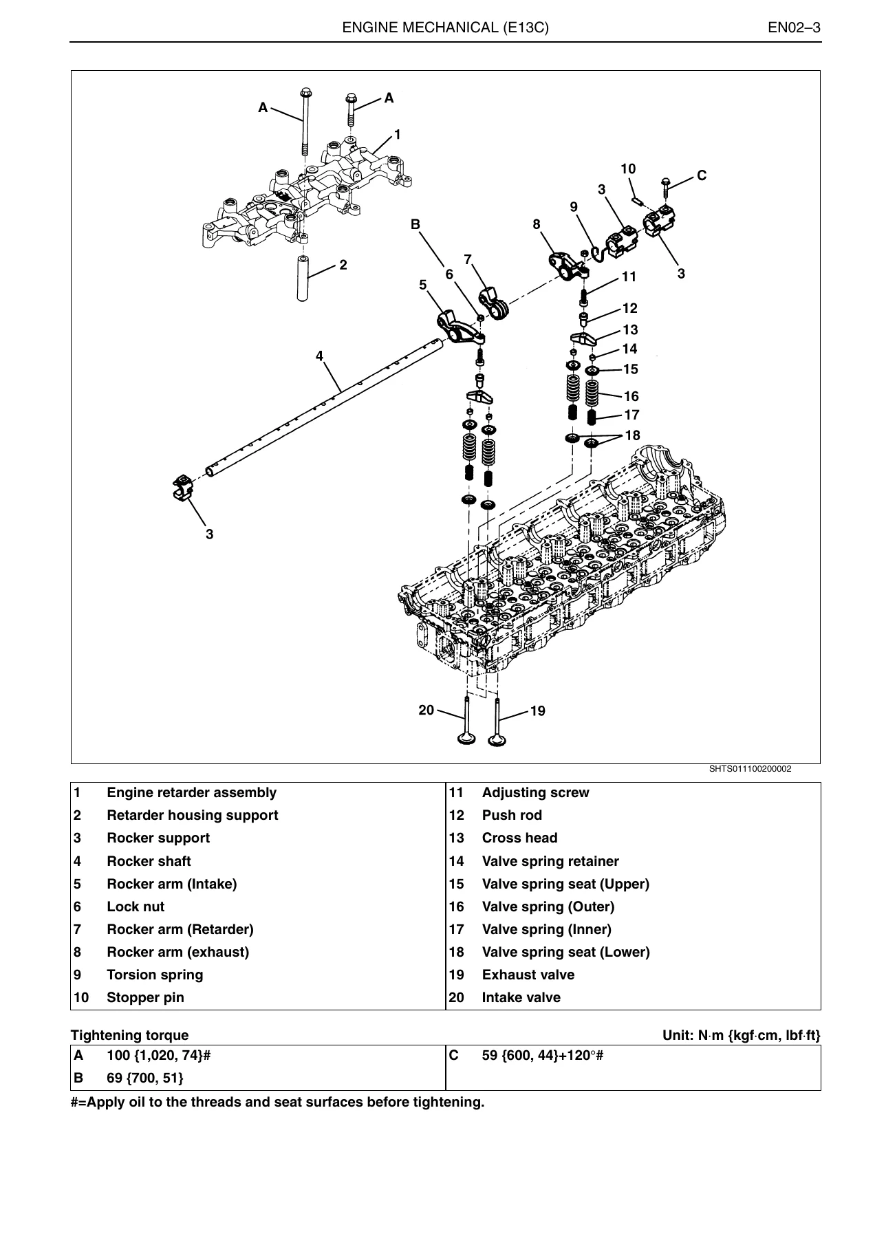
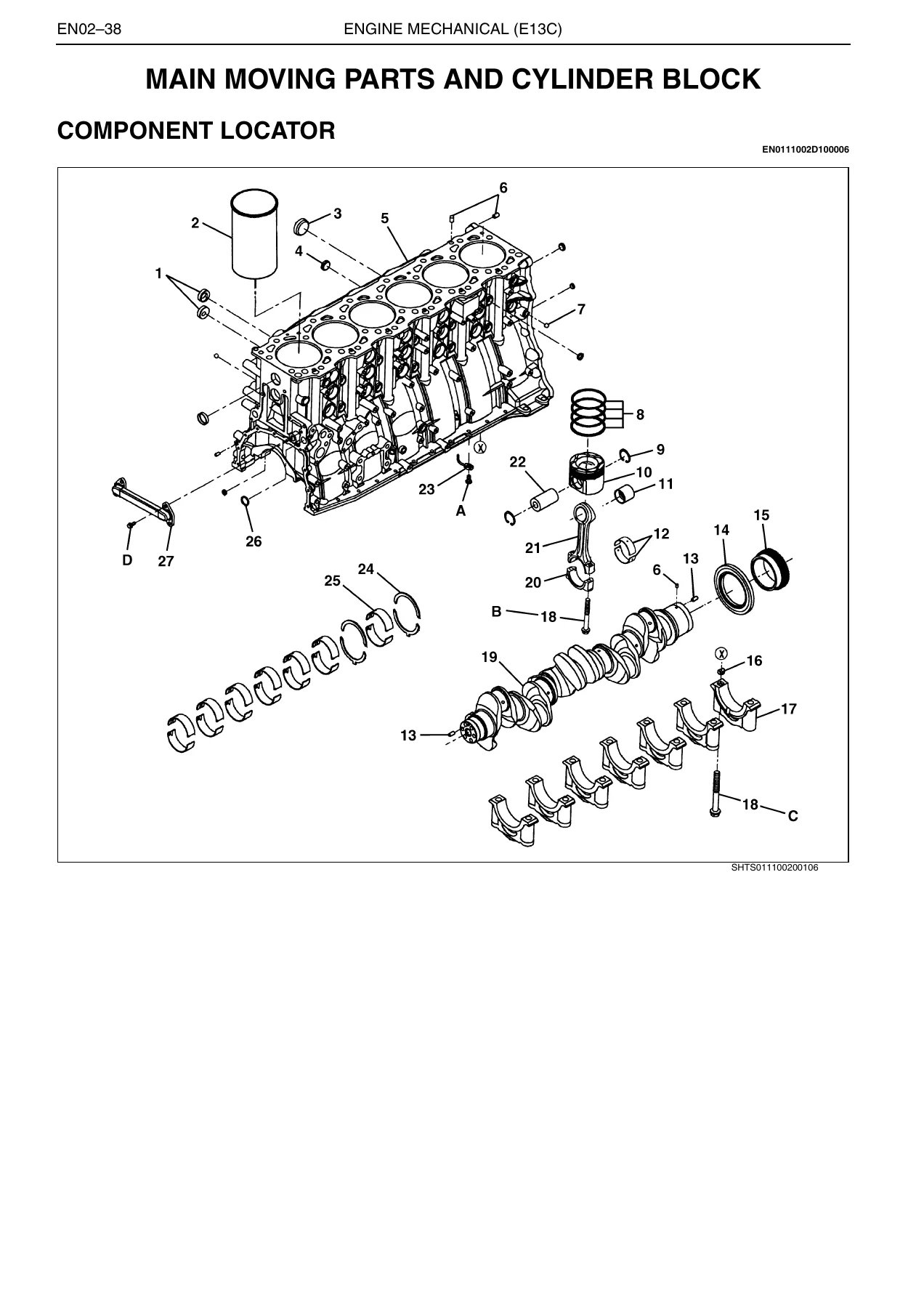
This is the full Hino E13C Engine Workshop Manual issued by Hino Motors, Ltd. under manual number S5-YE13E01A. It has been prepared to provide information regarding repair procedures on Hino vehicles applicable to the E13C engine, and it is written for the working service engineer rather than the driver. Every procedure is backed by the tightening torque, clearance, wear limit or special tool number the job demands, and the component locators follow the same exploded-view-plus-numbered-part-table format that Hino technicians work from on the shop floor.
If you are maintaining, overhauling or diagnosing an E13C or E13C-TI engine, this Hino E13C workshop manual is the reference that tells you the order to loosen a cylinder head bolt pattern, how far to press a crankshaft front oil seal, what the valve clearance should be when cold, which terminals to probe on the common rail ECU, and what each diagnosis monitor code is actually reporting.
File Details
- Manual type: Engine Workshop Manual (service, repair and overhaul)
- Manufacturer: Hino Motors, Ltd.
- Engine coverage: E13C / E13C-TI diesel
- Language: English
- File format: PDF
- Manual number: S5-YE13E01A
- Publication reference: Pub. No. S5-YE13E01A ’04-3
- Page count: 412 pages
Chapters Covered
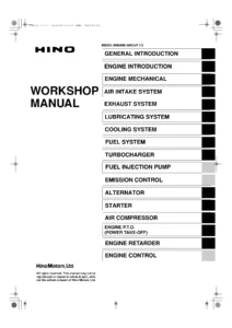
This E13C engine repair manual is organised into the following chapter groups, using Hino’s own wording and manual numbering:
- General Introduction (GN01-001)
- Engine Introduction (EN01-001)
- Engine Mechanical (EN02-001)
- Air Intake System (EN03-001)
- Exhaust System (EN04-001)
- Lubricating System (EN05-001)
- Cooling System (EN06-001)
- Fuel System (EN07-001)
- Turbocharger (EN08-001)
- Alternator (EN11-001 / EN11-002)
- Starter (EN12-001)
- Air Compressor (EN13-001 / EN13-002)
- Engine P.T.O. – Power Take-Off (EN14-001)
- Engine Retarder (EN15-001)
- Fuel Control (DN02-001)
General Introduction (GN01)
The opening chapter sets the ground rules that the rest of the Hino E13C service manual depends on: how to use the book, safety precautions, the classification of DANGER, WARNING, CAUTION and NOTICE statements, and the definition of direction, standard value, limit and standalone-unit orientation. It also contains the tightening standards you will use constantly – general standard bolt and nut torque tables by strength category (4T, 7T, 9T), the pre-coated bolt re-sealing procedure, the tension control with angular torquing method used in the plastic region of the material for cylinder head bolts, crankshaft main bearing cap bolts and connecting rod bearing cap bolts, flare nut and hose torque tables, tapered screw sealant procedure using LOCTITE #575, nylon tube joint assembly, joint and gasket assembly, and liquid gasket handling. The chapter closes with the chassis serial number, vehicle identification number and engine serial number locations.
Engine Introduction (EN01)
Engine assembly data and specifications, troubleshooting tables for the complete engine (overheating, excessive oil consumption, piston seizure, lack of power, exhaust leakage, difficulty starting, rough idling, diesel knock and unusual engine noise), common rail system troubleshooting, engine tune-up including valve clearance checking and adjusting, overhaul criteria, compression pressure measurement, engine oil pressure measurement, special tools, engine dismounting and mounting, and the liquid gasket application points for the E13C series.
Engine Mechanical (EN02)
The largest chapter in the E13C engine workshop manual, split into six major overhauls. Cylinder head covers valve guide and valve seat replacement, valve stem oil seal, nozzle seat, cam idle gear, camshaft assembly, rocker arm assembly, cylinder head bolt measurement and the staged 90-degree angular tightening sequence. Crankshaft front end covers the crankshaft damper and front oil seal replacement. Flywheel and flywheel housing covers rear oil seal replacement and ring gear renewal. Timing gear covers main idle gear, air compressor idle gear and cam idle gear removal, backlash and end play measurement, and the backlash adjustment procedure after cylinder head resurfacing. Main moving parts and cylinder block covers piston and connecting rod removal, piston ring servicing, cylinder liner removal and installation with A/B/C grading, liner protrusion measurement, piston cooling jet flow testing, crankshaft and main bearing cap installation with the 90-degree plus 45-degree angular torque procedure, and full inspection and repair tables for pistons, rings, pins, bearings, crank journals and the cylinder block.
Air Intake, Exhaust, Lubricating and Cooling Systems (EN03 to EN06)
Intake manifold and air pipe installation, air cleaner assembly and element inspection, and the air hose stopper and paint mark alignment procedure. The exhaust chapter covers the exhaust manifold and gasket orientation, exhaust manifold bracket, turbocharger and exhaust manifold connector tightening sequences, exhaust pipe, muffler, tail pipe and clamp installation. The lubricating chapter diagrams the full oil circuit and covers the oil pump outlet and inlet pipes, oil filter case, oil cooler and oil pump inspection with tip clearance, end play and gear backlash limits. The cooling chapter covers the coolant pump, thermostat opening temperature and lift testing, radiator disassembly and caulking using the radiator tool, radiator cap valve opening pressure, intercooler air leakage testing and cooling fan inspection.
Fuel System (EN07)
Supply pump removal and installation, coupling plate and drive gear alignment using the supply pump special tool at No.1 cylinder top dead centre of the compression stroke, and the on-vehicle pump control valve (PCV) and engine speed sub sensor resistance checks. It also covers the common rail – flow damper, pressure limiter and common rail pressure sensor removal, inspection and installation – and injector description, removal, on-vehicle resistance and insulation testing, installation with O-ring and clamp, and the critical step of entering injector QR/ID correction codes into the ECU. The fuel filter component locator and torque table complete the chapter.
Turbocharger (EN08)
Description of the variable geometry turbocharger (VGT) assembly, troubleshooting for black smoke, white smoke, loss of power, poor response, noise and vibration, special tools, PC diagnosis tool check-up, VG assembly cylinder stroke checking, overhaul criteria including turbine shaft radial play and thrust play measurement with a dial gauge, full component locator, disassembly and assembly, VGT cylinder stroke test values, and inspection and repair limits for the turbine shaft, bearing case, floating metal, thrust collar, back plate, blower case and impeller.
Alternator, Starter and Air Compressor (EN11 to EN13)
Two alternator variants are documented – the 24V-60A and the 24V-90A – each with data and specifications, description, troubleshooting, component locator, overhaul, performance test, voltage regulator test and inspection and repair table covering field coil and stator resistance, diode resistance, rotor shaft diameters and bearing bore limits. The starter chapter covers the 24V 6kW reduction gear (planetary gear) type with pinion, clutch, magnetic switch, brush holder, armature, yoke, planetary gear and drive housing servicing, plus pull-in, hold-in, plunger return and no-load performance tests. The air compressor chapter is supplied in two displacement variants, 340 cm3 and 496 cm3, covering cylinder head, valve seat, piston, piston ring, connecting rod, crankshaft, bearing holder and unloader valve overhaul with a full inspection and repair table.
Engine P.T.O. and Engine Retarder (EN14 and EN15)
Power take-off assembly description including driven gear, idle gear, main idle gear and crankshaft gear relationships, component locator, special tools, overhaul, oil seal and ball bearing replacement, flywheel and flange installation, and gear backlash measurement. The engine retarder chapter gives the component locator for the retarder assembly, housing support, solenoids, control valve spool, slave piston and master piston, the special slave piston spring press tool, disassembly and assembly of the slave piston and solenoid, and the slave piston clearance adjustment procedure cylinder by cylinder in firing order.
Fuel Control – Common Rail System and Diagnostics (DN02)
This is where the Hino E13C engine manual turns into a full electronic diagnostic reference. It opens with a common rail fuel injection system overview and component locator, an electrical system diagram, the wiring layout, and detailed precautions for working on the injector drive circuit – including the warning that approximately 110V is generated for injector drive actuation. The chapter then provides inspection procedures, diagnosis using the diagnosis monitor, diagnosis using the PC diagnosis tool with interface, the diagnosis monitor code and diagnosis trouble code table with MC numbers, DTC numbers, symptom classification and check engine lamp status, ECU power supply voltage and ground checks, injector correction data, main relay, coolant temperature sensor, engine speed main and sub sensors, fuel temperature sensor, vehicle speed sensor, accelerator sensor 1 and 2, accelerator sensor for P.T.O. operation, air intake heater, engine retarder, VGT valve 1, 2 and 3, boost pressure sensor, turbocharger speed sensor, turbocharger overrun and over boost, clutch switch, accelerator switch, idle set controller, starter switch, engine stop switch, neutral switch, transmission position detect switch, injector solenoid valve system breaking, injector solenoid valve driving system GND short-circuit and +B short-circuit, cylinder contribution/balance faults, common rail pressure fixed output, common rail pressure sensor, common rail excessive pressure, pump control valve 1 and 2, and supply pump diagnostics. Signal check harness pin assignments are given for contact boxes A through E, so you can probe the correct terminal on the first attempt instead of the third.
Engine Data You Can Work From
The E13C-TI is documented in the engine assembly data table as a diesel, 4 cycle, vertical, 6 cylinder, in-line overhead camshaft, water-cooled, direct injection engine, turbocharged with intercooler. Bore and stroke 137 x 146 mm (5.394 x 5.748 in.), piston displacement 12.913 L (788.0 cu.in.), compression ratio 17.5:1, firing order 1-4-2-6-3-5 with cylinders counted from the crankshaft pulley side, direction of rotation counterclockwise viewed from the flywheel, compression pressure 3.3 MPa (34 kgf/cm2, 479 lbf/in.2) at 200 r/min, maximum revolution 2,100 or 2,400 r/min, idling revolution 500 r/min and dry weight 1,250 kg (2,756 lbf). Valve seat and valve face angles are given as intake 30 degrees and exhaust 45 degrees. Valve clearance when cold is specified as 0.28 mm (0.0110 in.) for intake and 0.49 mm (0.0193 in.) for exhaust. Compression pressure limit is 3.0 MPa (31 kgf/cm2, 435 lbf/in.2).
What Makes This Hino E13C Workshop Manual Different
This is not a generic diesel engine book with a Hino cover dropped on it. The procedures are E13C specific – the cylinder head bolt sequence runs to 28 numbered bolts with two additional bolts, the main bearing cap torque steps through a loosening and re-tightening cycle before the 90-degree and 45-degree angular turns, the piston cooling jet is tested at 196 kPa with a target circle gauge, and the cylinder liner is matched to the block using engraved A, B or C markings. The common rail diagnostics reference the actual ECU terminal designations – VB1, VB2, VB3, PGD1, PGD2, PGD3, SPV1, SPV2, INJ1 through INJ6, PCR1, PCR2, AGD1 – so the diagnostic tables line up with the connector in front of you.
Who This Manual Is For
Fleet workshops running Hino trucks with E13C power, independent diesel mechanics taking on a top-end or full overhaul, technical colleges teaching common rail diagnostics on Japanese heavy diesel, and owners of equipment powered by the E13C-TI who want to understand what their workshop is doing and why. Anyone performing maintenance or repairs is expected by the manual itself to be a qualified service engineer who has acquired expertise, and to use the special tools described rather than improvised methods – the book states plainly that non-recommended work methods or tools can impair the safety and reliability of the vehicle.
Get the Hino E13C Engine Workshop Manual Delivered Instantly
IMAGES PREVIEW
The Hino E13C Engine Workshop Manual PDF gives you the capability to carry out everything from a valve clearance check to a complete engine overhaul, from a thermostat test to a full common rail diagnosis with the ECU pinout in front of you. It tells you the correct procedure and the correct specification for each job, which is what separates a repair that lasts from a comeback. Torque values, wear limits, angular tightening sequences, special tool part numbers, exploded views and diagnostic code tables are all in one document that you can keep on the workshop laptop, open on a tablet at the machine, or print the pages you need and take them under the vehicle with you. Delivery is instant – the PDF is available for download immediately after payment, with no shipping, no waiting and no restriction on which device you read it on.
Reviews
There are no reviews yet.