
Hino E13C Engine Workshop Manual S5-YE13E01E – Complete Diesel Engine Service, Overhaul & Fuel Control Repair Guide (PDF)
Original price was: $55.95.$34.95Current price is: $34.95.
Hino E13C engine workshop manual S5-YE13E01E covering cylinder head, timing gears, crankshaft, pistons and liners, cooling, lubrication, common rail fuel system, VGT turbocharger, retarder, air compressor, P.T.O. and full fuel control diagnostics. 416-page PDF with torque tables, service limits, special tools and exploded views.
Description
Hino E13C Engine Workshop Manual – The Complete Diesel Engine Service Reference
This is the Hino E13C engine workshop manual, publication S5-YE13E01E, prepared by Hino Motors, Ltd. for repair procedures on Hino vehicles powered by the E13C engine. Across 416 pages it takes a technician from general workshop practice and engine tune-up through complete mechanical overhaul of the cylinder head, timing gear train, crankshaft, pistons and liners, and onward into the air intake, exhaust, lubricating, cooling and common rail fuel systems. Every procedure is written for a qualified service engineer working with the specified special tools, and the values are printed as usable data – tightening torques, assembly standards, service limits and clearance ranges – not as vague guidance.
What separates this Hino E13C workshop manual from a generic engine book is that it treats the E13C as a system: mechanical repair chapters sit alongside a dedicated fuel control chapter that carries the diagnosis monitor codes, DTC tables, sensor circuit checks and pump control valve troubleshooting for the common rail injection system. If you are maintaining, diagnosing or rebuilding an E13C, this is the document that keeps the specifications, the tooling and the diagnostic logic in one place.
File Details
- Manual type: Engine Workshop Manual
- Brand / manufacturer: Hino Motors, Ltd.
- Engine: E13C (E13C-TI)
- Publication number: S5-YE13E01E
- Language: English
- Page count: 416 pages
- File format: PDF
Chapters Covered
- General Introduction (GN01)
- Engine Introduction (EN01)
- Engine Mechanical (EN02)
- Air Intake System (EN03)
- Exhaust System (EN04)
- Lubricating System (EN05)
- Cooling System (EN06)
- Fuel System (EN07)
- Turbocharger (EN08)
- Alternator – E13C: 24V-60A and 24V-90A (EN11)
- Starter (EN12)
- Air Compressor – E13C: 340 cm3 and 496 cm3 types (EN13)
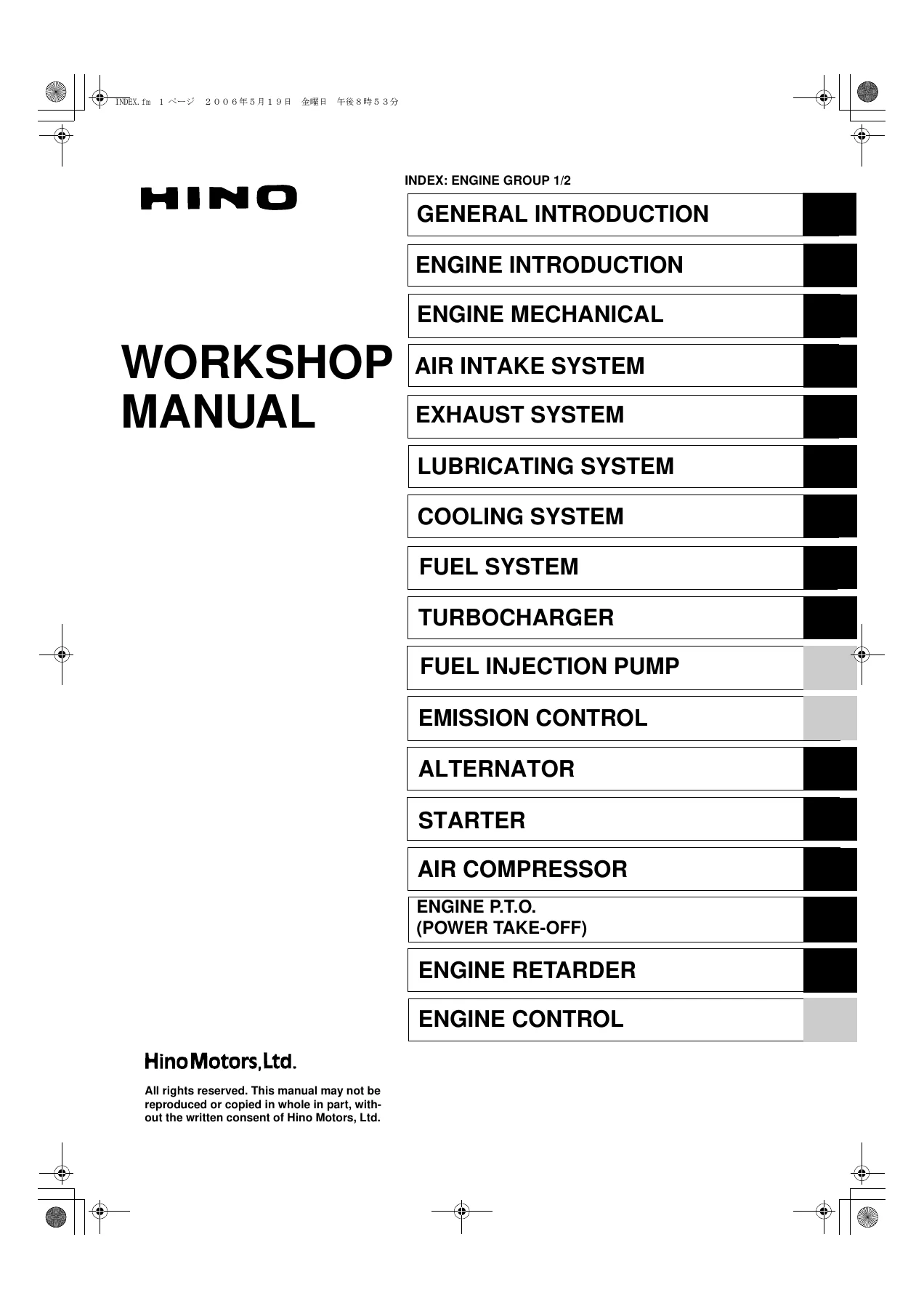
- Engine P.T.O. (Power Take-Off) (EN14)
- Engine Retarder (EN15)
- Fuel Control (DN02)
General Introduction and Engine Introduction
Before a single bolt is turned, this Hino E13C engine workshop manual establishes the working rules: how to read the component locator pages and the alphabetical torque markings, how the manual defines standard value versus service limit, the safety classifications used in the procedures, and the general tightening torque tables for standard bolts, nuts, pre-coated bolts and the angular torquing method used in the plastic region on cylinder head and bearing cap bolts. The engine introduction section then delivers the E13C data and specifications, the troubleshooting charts by symptom – overheating, excessive oil consumption, piston seizure, lack of power, exhaust leakage, hard starting, rough idling, diesel knock and unusual engine noise – the engine tune-up procedure for valve clearance checking and adjustment, and the overhaul criteria covering compression pressure measurement and oil pressure evaluation.
Engine Mechanical – Cylinder Head, Crankshaft, Flywheel and Timing Gear
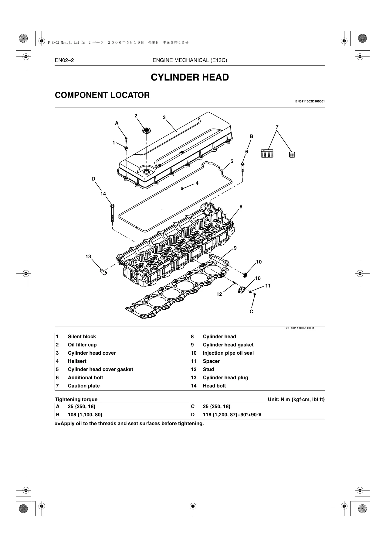
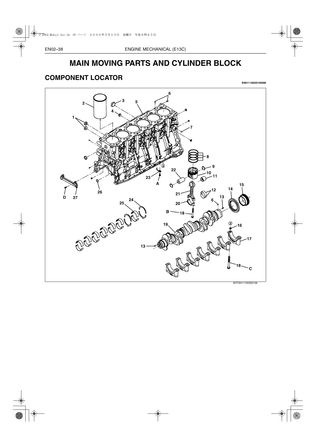
This is the heart of the rebuild work. The cylinder head chapter runs through disassembly, valve guide and valve seat replacement, valve stem oil seal fitting, nozzle seat replacement, cam idle gear replacement, camshaft and rocker arm assembly, cylinder head bolt measurement, the full head bolt torque sequence and the angular stages that follow it. The crankshaft front end chapter covers the front oil seal, crankshaft damper and pulley with their tightening order and angular torque stages. The flywheel and flywheel housing chapter handles rear oil seal replacement, ring gear replacement by heating, flywheel bolt tightening order and the inspection limits for flywheel surface deflection and flange depth. The timing gear chapter explains backlash measurement and adjustment – including the procedure required when the cylinder head lower surface has been ground – and the component locator pages show every idle gear and thrust plate in exploded form. The main moving parts and cylinder block chapter covers piston and connecting rod disassembly, cylinder liner removal and installation with the A, B and C matching marks, liner protrusion measurement, piston cooling jet flow testing, piston ring orientation, main bearing cap and connecting rod bolt torque sequences, plus the inspection and repair tables for piston clearance, ring end gaps, crank pin and journal diameters, and crankshaft end play.
Air Intake and Exhaust Systems
The intake side of this Hino E13C engine manual documents the intake manifold and air pipe layout, intake manifold gasket orientation, air hose clamping and stopper alignment, the air cleaner assembly and the inspection points on the dust indicator and filter element. The exhaust system chapter covers the exhaust manifold and gasket installation with its staged nut tightening order, the manifold bracket procedure, turbocharger to manifold connector torques, and the muffler, tail pipe and exhaust pipe clamp installation – including the warning about clamp orientation and the sequence of tightening the upper bolt before the lower.
Lubricating System and Cooling System
The lubricating system chapter opens with a full oil flow diagram showing the main oil hole, sub oil hole, regulator valve, check valve, anti-drain valve, oil filter safety valve and oil cooler safety valve with their opening pressures. From there it moves into the oil cooler, oil filter case, oil filter and oil pump – gear tip clearance, end play, drive gear clearance and gear backlash limits – all given as standard and limit values with the remedy for each. The cooling system chapter documents the coolant pump description and overhaul, the thermostat opening temperature and valve lift test, the radiator overhaul including upper and lower tank separation with the radiator tool, O-ring seating and tang caulking, coolant hose alignment marks, and the cooling fan and fan clutch inspection points.
Fuel System – Common Rail, Supply Pump and Injectors
For the E13C common rail system this manual gives the component locator with the common rail assembly, injector clamps and supply pump, the removal and installation of the supply pump with the coupling plate and the special tool used to confirm No.1 cylinder top dead centre, the pump control valve and engine speed sub sensor resistance checks, the common rail overhaul covering flow damper, pressure limiter and common rail pressure sensor with their tightening torques, and the injector chapter with on-vehicle resistance and insulation checks, O-ring fitting, injector clamp gap measurements and the requirement to enter the injector QR/ID codes into the ECU after replacement. Fuel filter servicing with the air bleeder plug, drain plug and element set spring completes the fuel section.
Turbocharger – Variable Geometry Assembly
The turbocharger chapter describes the variable geometry turbocharger assembly and its components, gives the troubleshooting chart for black smoke, white smoke, power loss, poor response and abnormal noise, and then sets out the on-vehicle overhaul criteria: turbine shaft rotation check, radial play measurement and thrust play measurement using the tool assembly, with the service limits printed for each. The overhaul section covers VGT assembly removal without disturbing the factory-set bolts, blower case and impeller removal, bearing case disassembly, floating metal and thrust bearing assembly, seal ring replacement and the VGT cylinder stroke check across all three ports.
Alternator, Starter, Air Compressor, P.T.O. and Engine Retarder
The electrical and accessory chapters give the 24V-60A and 24V-90A alternator specifications, circuit diagrams, troubleshooting by symptom, disassembly and assembly with bearing, rotor, stator, rectifier holder and regulator procedures, plus the resistance and performance tests. The starter chapter covers the reduction gear type starter, its component locator, disassembly and assembly with grease points, pull-in, hold-in and plunger return tests and the no-load performance test. Air compressor coverage is provided for both the 340 cm3 and 496 cm3 types, including drive gear timing and the inspection gauge check through the timing gear case inspection hole. The engine P.T.O. chapter handles driven gear, idle gear, oil seal and ball bearing replacement with backlash limits, and the engine retarder chapter covers slave piston removal and installation with the spring press, solenoid seal rings, and the slave piston clearance adjustment of 1.3 mm when cold.
Fuel Control – Diagnostics and ECU Troubleshooting
The fuel control chapter is effectively a diagnostic manual on its own. It opens with the common rail system overview, component locator, wiring diagram and electrical schematic, then lays out the precautions for working around the injector drive circuit, the signal check harness connection and the ECU pin assignment across contact boxes A to E. From there it provides the diagnosis monitor code and DTC table, the check engine lamp status test, diagnosis monitor and PC diagnosis tool procedures, and then individual troubleshooting flows for the ECU power supply and ground, coolant temperature sensor, engine speed main and sub sensors, fuel temperature sensor, vehicle speed sensor, accelerator sensor 1 and 2, accelerator sensor for P.T.O. operation, air intake heater, engine retarder, VGT valve 1, 2 and 3, boost pressure sensor, turbocharger speed sensor, clutch switch, accelerator switch, auto cruise switch, idle set controller, starter switch, engine stop switch, neutral switch, transmission position detect switch, injector solenoid valve circuits, cylinder contribution and balance faults, common rail pressure faults, and pump control valve 1 and 2 faults.
Why This Hino E13C Workshop Manual Belongs in the Workshop
An E13C is not an engine you troubleshoot by feel. The common rail injection system, the variable geometry turbocharger and the electronic retarder all depend on measured values – a resistance across a sensor terminal, a rail pressure voltage, a stroke on a VGT cylinder rod – and this manual supplies those values alongside the mechanical specifications that govern the rebuild itself. Having the Hino E13C engine workshop manual on hand means the cylinder head bolt sequence and angular stages are followed exactly, the liner matching marks are read correctly, the injector ID codes get written into the ECU so idle quality and noise stay as designed, and a diagnostic code leads to a defined test path instead of a parts swap.
The scope covers the jobs that actually come through the door: a top-end overhaul, a liner and piston replacement, a front or rear oil seal, a timing gear backlash correction after a head resurface, an oil pump or coolant pump change, a supply pump replacement with correct drive gear timing, a turbocharger overhaul or VGT stroke check, air compressor and P.T.O. servicing, retarder slave piston adjustment, and full electronic diagnosis of the fuel control system. Because both air compressor sizes, both alternator ratings and both engine speed sensor circuits are documented, the same file serves across the E13C variants described in the book.
IMAGES PREVIEW
Delivery is instant. The moment payment clears, the complete 416-page PDF is available to download – no shipping, no waiting on a courier, no missing binder. Open it on a laptop in the cab, a tablet on the bench or a phone under the truck, print the pages you need for the job at hand, and keep the file for the next E13C that rolls in. One purchase, one file, every specification and diagnostic path the E13C engine needs.
Reviews
There are no reviews yet.