
Hino E13C Engine Workshop Manual – PDF Service & Repair Guide
Original price was: $74.95.$44.95Current price is: $44.95.
Complete Hino E13C diesel engine workshop manual as a PDF. Covers cylinder head, timing gear, cylinder block, turbocharger, air compressor, common rail fuel system, and full diagnostics for the E13C-TI engine.
Description
The Hino E13C Engine Workshop Manual is a comprehensive PDF service and repair guide covering the E13C-TI diesel engine — a 12.913 L inline-six, water-cooled, direct-injection powerplant with overhead camshaft and turbocharged/intercooled aspiration, used in Hino heavy-duty truck applications. This is not a generic engine book. It is the workshop manual for the E13C family, walking through every major system with step-by-step overhaul procedures, exploded component views, torque specifications, wear limits, and diagnostic tables.
If you maintain, rebuild, or repair Hino trucks powered by the E13C, this manual is the reference you keep on the bench. It covers the complete engine assembly from cylinder head to flywheel housing, including the common rail fuel injection system, variable geometry turbocharger, air compressor, and power take-off assembly.
File Details
- Manual type: Engine Workshop Manual
- Brand: Hino
- Model: E13C / E13C-TI
- Engine: Diesel, 4-cycle, vertical, 6-cylinder, in-line overhead camshaft, water-cooled, direct injection
- Language: English
- Page count: 272
- File format: PDF
Chapters Covered
- Engine Introduction (E13C)
- Cylinder Head
- Crankshaft Front End
- Flywheel and Flywheel Housing
- Timing Gear
- Main Moving Parts and Cylinder Block
- Air Intake System
- Lubricating System
- Cooling System
- Fuel System
- Turbocharger
- Air Compressor
- Power Take-Off Assembly
- Common Rail Fuel Injection System
- Fuel Control (E13C)
Engine Introduction (E13C)
This opening chapter sets out the E13C engine data and specifications — bore and stroke, displacement, compression ratio, firing order, valve timing, compression pressure, and idling speed — along with a full troubleshooting section covering engine overheating, excessive oil consumption, piston seizure, lack of power, exhaust leakage, hard starting, rough idling, diesel knock, and unusual engine noise. The common rail system troubleshooting tables are also here. Engine tune-up procedures, including valve clearance checking and adjustment with the cross head and rocker arm, are detailed step by step.
Cylinder Head
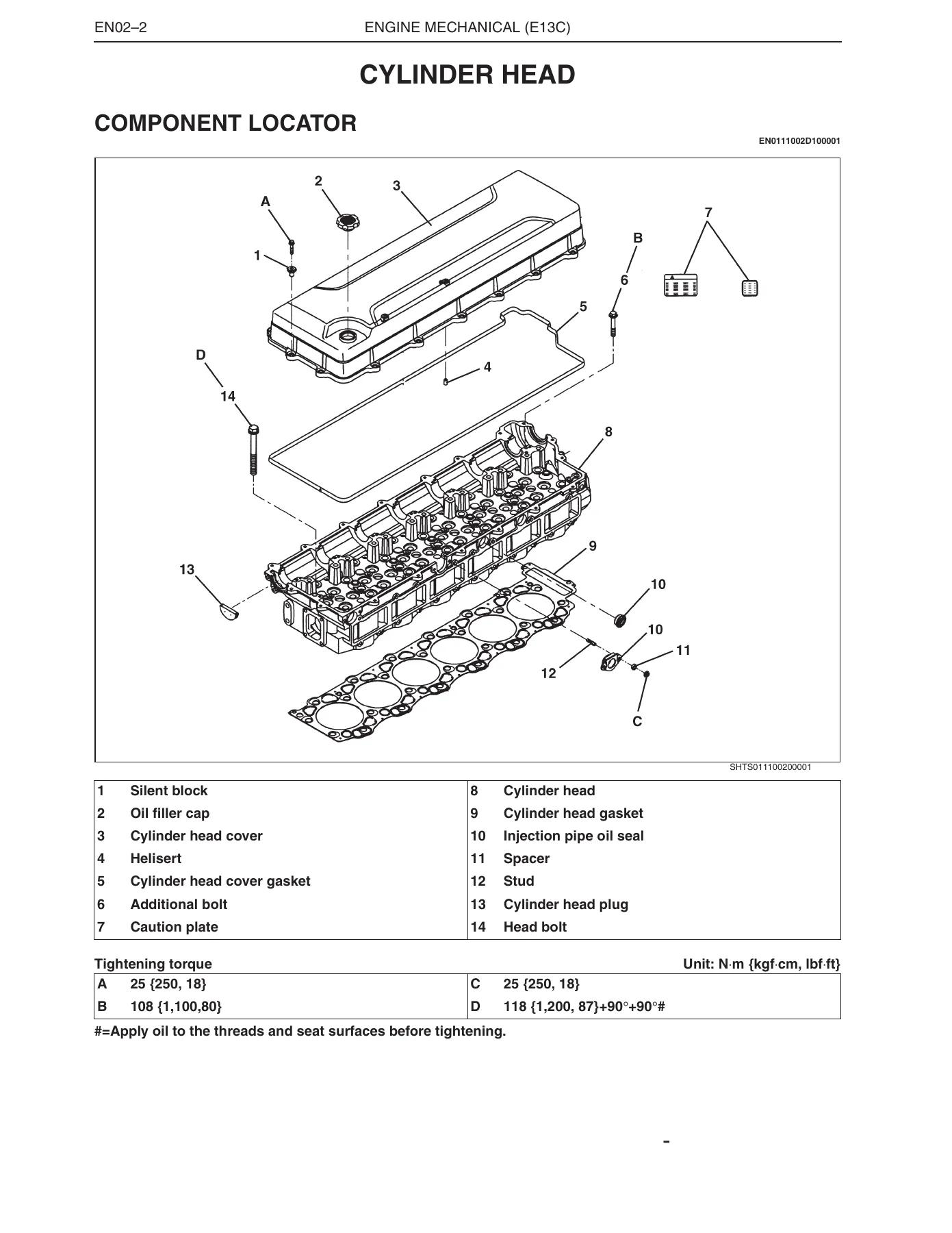
Covers the complete disassembly, inspection, repair, and reassembly of the E13C cylinder head. You get the valve guide and valve seat replacement procedures with press-fit dimensions, valve stem oil seal installation, nozzle seat replacement and caulking, cam idle gear service, and the full cylinder head bolt tightening sequence with the torque-plus-angle method. Camshaft bearing clearance, cam height limits, and rocker arm bushing wear limits are included in the inspection tables.
Crankshaft Front End and Flywheel
Front end coverage includes crankshaft damper installation, front oil seal replacement with the oil seal press and puller tools, and the tightening sequence for the damper bolts. The flywheel and flywheel housing chapter covers rear oil seal replacement, flywheel ring gear replacement using heat, flywheel surface deflection limits, and the flywheel bolt tightening order.
Timing Gear
The timing gear chapter describes the gear train layout — crankshaft gear, main idle gear, cam idle gears for both cylinder block and cylinder head sides, air compressor idle gear, and power steering pump drive gear. You get backlash measurement procedures for every gear mesh, idle gear shaft removal with a sliding hammer, and the critical backlash adjustment procedure required after grinding the cylinder head lower surface.
Main Moving Parts and Cylinder Block
This is the core of any engine overhaul. It covers piston and connecting rod removal, piston ring service, piston pin fitting, cylinder liner removal and installation with the three-tier A/B/C clearance matching system, liner protrusion measurement, crankshaft installation with main bearing cap torque sequences, thrust bearing orientation, connecting rod bolt torque-plus-angle tightening, and piston cooling jet inspection and flow testing. Inspection and repair tables give clearances for crank pin to connecting rod bearing, crank journal to main bearing, cylinder liner to piston, and crankshaft end play.
Lubricating System
Includes a full lubrication circuit diagram showing every oil gallery and component from the oil strainer through the oil pump, oil cooler, oil filter, and main oil hole to the turbocharger, supply pump, piston cooling jets, and rocker arm assembly. The oil filter assembly is broken down with bypass and full-flow elements, regulator valve, check valve, and anti-drain valve. Oil pump inspection covers tip clearance, end play, gear backlash, and drive gear clearance.
Cooling System
The cooling system chapter covers the coolant pump with case sub-assembly and cover, thermostat testing with opening temperature and valve lift specifications, radiator service, and cooling fan inspection. A system diagram shows the flow through the engine, radiator, thermostat case, and reservoir tank.
Fuel System and Common Rail
The fuel system section covers the supply pump, common rail assembly, injectors, fuel filter, and the complete common rail fuel injection system overview. You get procedures for supply pump removal and installation with timing gear alignment, flow damper service, pressure limiter testing, common rail pressure sensor inspection, and injector electrical testing with resistance values. The common rail system description explains the ECU-controlled fuel injection quantity, injection pressure, injection timing, and injection rate.
Turbocharger
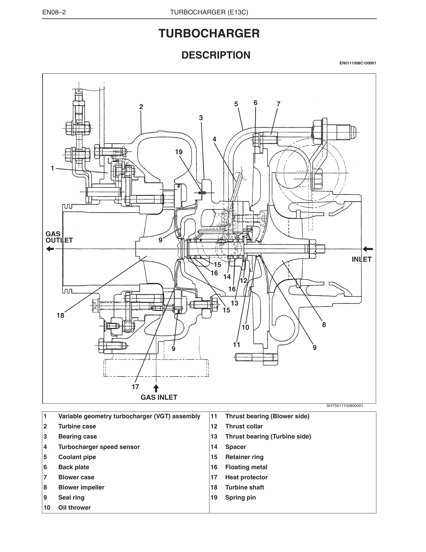
Covers the variable geometry turbocharger (VGT) assembly with a full cutaway description, troubleshooting table, radial and thrust play measurement using the dial gauge and special tool assembly, VGT assembly removal, blower impeller service, bearing case disassembly with floating metal and thrust bearing replacement, seal ring replacement, and VGT cylinder stroke checking on the bench. Boost pressure checking is also covered.
Air Compressor
Two air compressor types are covered: the 340 cm³ and 496 cm³ single-cylinder, water-cooled, forced-feed lubricated compressors. The chapter includes disassembly, piston and connecting rod service, crankshaft and bearing replacement, unloader valve service, drive gear installation with timing, and inspection tables for piston clearance, piston pin clearance, connecting rod end play, and crankshaft end play.
Power Take-Off Assembly
Covers the engine PTO gear train, driven gear and idle gear removal and installation, oil seal replacement, ball bearing replacement, gear backlash measurement, and flywheel housing mounting.
Fuel Control (E13C)
The fuel control chapter is the diagnostic heart of the common rail system. It includes the full diagnosis monitor code and diagnostic trouble code table, ECU pin assignments, signal check harness connection procedures, and step-by-step diagnostic flowcharts for every sensor and actuator: coolant temperature sensor, engine speed main and sub sensors, fuel temperature sensor, vehicle speed sensor, accelerator sensors 1 and 2, PTO accelerator, air intake heater, engine retarder, VGT valves, boost pressure sensor, turbocharger speed sensor, clutch switch, accelerator switch, idle set controller, starter switch, engine stop switch, neutral switch, transmission position detect switch, injector circuits, PCV circuits, and common rail pressure sensor. Each diagnostic path gives terminal numbers, standard voltages or resistances, and the conditions under which the reading should be taken.
Pre-Coated Bolts and Torque-to-Yield Fasteners
The manual includes specific instructions for pre-coated bolts, including when sealant must be reapplied and how to reuse them correctly. The tension control with angular torquing method in the plastic region is also covered, with the caution to measure bolt length before assembly and replace any bolt that exceeds the use limit.
Liquid Gasket Application
Liquid gasket types — Three Bond TB1207B, TB1207C, and TB1211 — are identified along with application points, widths, and the critical time windows: assemble parts within 20 minutes of application, and wait at least 15 minutes after assembly before starting the engine. The manual shows application patterns for the oil seal retainer, breather pipe, cylinder head plate, pressure sensor seal, and block lower face.
Who This Manual Is For
This Hino E13C workshop manual is written for diesel technicians, fleet maintenance shops, engine rebuilders, and serious owner-operators who need to service or overhaul the E13C-TI engine. The procedures assume access to common workshop tools plus the special tools listed in each chapter, and the torque specifications and wear limits are given in metric units with imperial conversions throughout.
Get the Complete Hino E13C Workshop Manual as a PDF
The Hino E13C Engine Workshop Manual puts the full service and repair procedure for this 12.9 L diesel engine at your fingertips. You can diagnose a hard-starting or low-power complaint using the troubleshooting tables, set valve clearance and cam timing to factory specifications, torque every critical fastener correctly with the angular method, measure wear against real limits before ordering parts, and rebuild the cylinder head, turbocharger, air compressor, or common rail system with confidence. Getting the torque values, clearances, and diagnostic voltages right the first time is what separates a repair that lasts from a comeback. This manual gives you those numbers.
IMAGES PREVIEW
Delivered as an instant PDF download after purchase — no shipping, no waiting. Open it on a laptop, tablet, or phone in the workshop, print the pages you need, and keep the rest of the manual on file. One download gives you the complete Hino E13C engine workshop manual.
Reviews
There are no reviews yet.