
Hino E13C Engine Workshop Manual – E13C-TI Diesel Repair Manual PDF
Original price was: $39.95.$23.95Current price is: $23.95.
Complete Hino E13C workshop manual for the E13C-TI diesel engine – 412 pages of overhaul, component locator, torque, diagnostic and troubleshooting procedures in an instant-download PDF.
Description
Hino E13C Engine Workshop Manual – E13C-TI Diesel Repair Manual
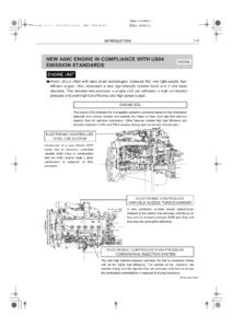
This is the full Hino workshop manual prepared for repair procedures on Hino vehicles fitted with the E13C engine. It opens with the general introduction that governs every job in the book – safety warnings, how to use the manual, work precautions, tightening of bolts and nuts for engine and chassis, flare nut and hose torque, sealant application on tapered pipe screws, nylon tube handling, joint and gasket assembly, liquid gasket application, and the full troubleshooting workflow from the trouble list through the diagnosis monitor to the PC diagnosis tool with interface. From there it moves into the E13C-TI engine itself, covering mechanical overhaul, air intake, exhaust, lubrication, cooling, fuel, turbocharger, alternator, starter, air compressor, engine P.T.O., engine retarder and the common rail fuel control system.
File Details
- Manual type: Workshop Manual (repair procedures)
- Brand: Hino Motors, Ltd.
- Engine covered: E13C / E13C-TI
- Publication number: S5-YE13E01A
- Publication date shown: ’04-3 (March 2004)
- Language: English
- Page count: 412 pages
- File format: PDF
Chapters Covered
- General Introduction – Warning, How to Use This Manual, Precautions for Work, Tightening of Bolts and Nuts for Engine and Chassis, Tightening of Flare Nuts and Hoses, Sealant on the Tapered Screw for Piping, Nylon Tube, Assembly of Joint/Gasket for Piping, Handling of Liquid Gasket, Troubleshooting Using the Trouble List, Troubleshooting Using a Diagnosis Monitor, Diagnosis Using the PC Diagnosis Tool with Interface, Chassis Serial Number / Vehicle Identification Number and Engine Serial Number
- Engine Introduction – Data and Specifications, Troubleshooting, Troubleshooting (Common Rail System), Engine Tuneup, Overhaul Criteria, Special Tools, Dismounting and Mounting, Liquid Gasket and Application Points
- Engine Mechanical – Cylinder Head, Crankshaft Front End, Flywheel and Flywheel Housing, Timing Gear, Main Moving Parts and Cylinder Block (each with Component Locator, Special Tools, Overhaul, Inspection and Repair)
- Air Intake System – Intake Manifold and Air Pipe, Air Intake, Air Cleaner
- Exhaust System – Exhaust Manifold and Pipe, Exhaust Pipe and Muffler
- Lubricating System – Diagram, Lubrication System, Oil Cooler, Oil Filter, Oil Pump
- Cooling System – Diagram, Coolant Pump, Thermostat, Radiator, Cooling Fan
- Fuel System – Diagram, Component Locator, Common Rail, Injector, Fuel Filter
- Turbocharger – Description, Troubleshooting, Special Tool, Checkup Using PC Diagnosis Tool, Checking the VGT Assembly, Inspection and Repair
- Alternator – E13C 24V-60A and E13C 24V-90A versions with Data and Specifications, Description, Troubleshooting, Component Locator, Overhaul, Inspection and Repair
- Starter (E13C) – Data and Specifications, Description, Troubleshooting, Component Locator, Overhaul, Inspection and Repair
- Air Compressor (E13C) – 340 cm3 type and 496 cm3 type with Data and Specifications, Troubleshooting, Component Locator, Special Tools, Overhaul, Inspection and Repair
- Engine P.T.O. (Power Take-Off) (E13C) – Description, Component Locator, Special Tool, Overhaul, Inspection and Repair
- Engine Retarder (E13C) – Component Locator, Special Tool, Overhaul
- Fuel Control (E13C) – Common Rail Fuel Injection System overview, Component Locator, Diagram, Electrical, Precautions, Inspection, Diagnosis Using the Diagnosis Monitor, Diagnosis Using the PC Diagnosis Tool with Interface, Diagnosis Monitor Code and Diagnosis Trouble Code Table, plus individual diagnostics for ECU power supply, ground, injector correction data, ECU, main relay, engine overheat, engine overrun, coolant temperature sensor, engine speed main and sub sensors, fuel temperature sensor, vehicle speed sensor, accelerator sensors 1 and 2 and the P.T.O. accelerator sensor, air intake heater, engine retarder, VGT valves 1 to 3, boost pressure sensor, turbocharger speed sensor, turbocharger overrun and over boost, clutch switch, accelerator switch, idle set controller, starter switch, engine stop switch, neutral switch, transmission position detect switch, injector solenoid valve system breaking and short circuits, cylinder contribution/balance, common rail pressure, pump control valves 1 and 2, and supply pump faults
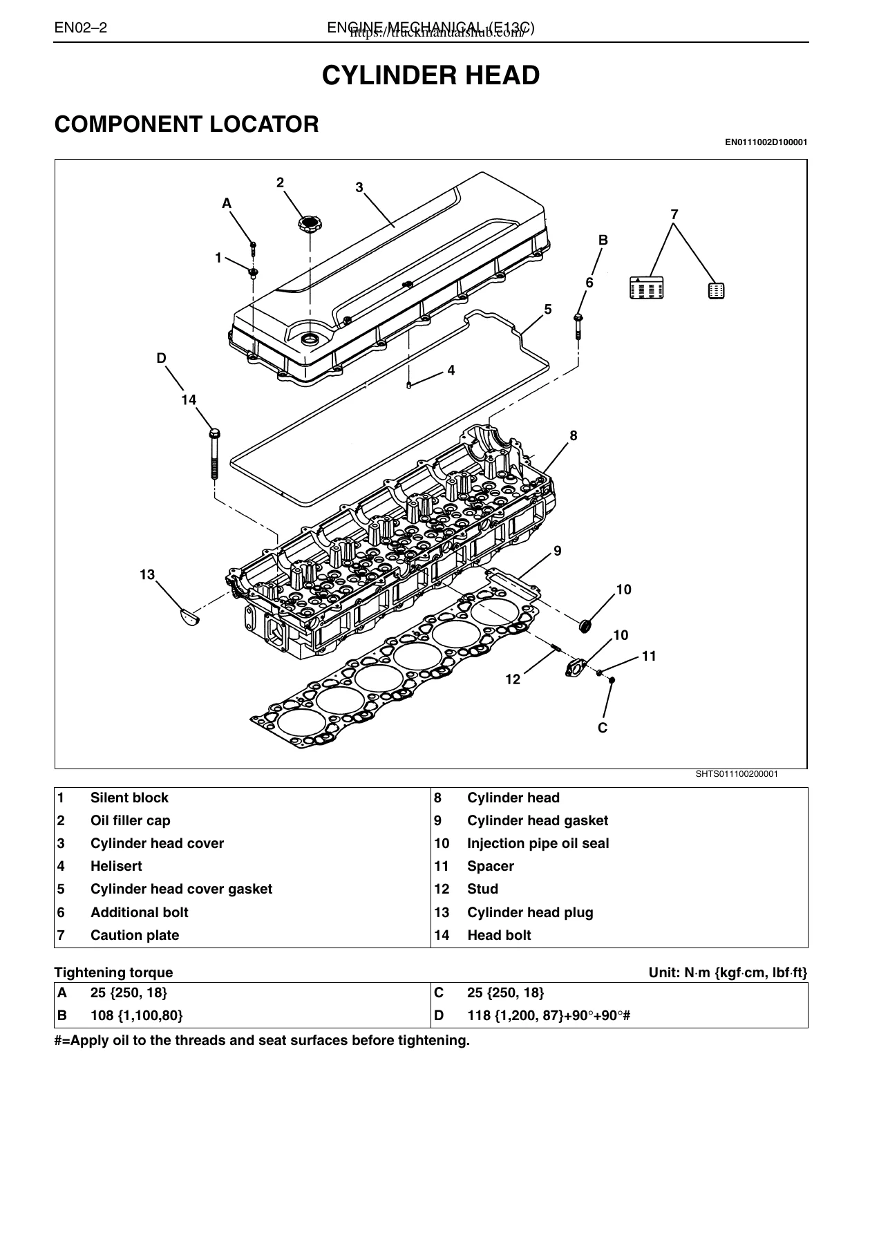
Laid out as a working reference rather than a reading book, this Hino E13C workshop manual gives you the component locators with numbered part tables, the tightening torque tables with alphabetical callouts, the tightening sequences, the special tool part numbers and the inspection criteria that sit behind every job on the E13C-TI. Exploded views and sectioned illustrations accompany the disassembly, inspection and assembly steps, so a rebuilder can see how the cylinder head, rocker arm assembly, camshaft, timing gear train, crankshaft, main bearing caps, pistons and connecting rods go together before anything comes apart. The liquid gasket and application-point tables specify exactly which sealer goes where and how wide the bead should be, which matters when you are re-sealing the oil seal retainer, breather pipe, cylinder head plate, cylinder head plugs and pressure sensor seal.
Diagnostic and Troubleshooting Content
Two diagnostic paths run through the book. The engine introduction carries a symptom-based troubleshooting section for engine overheating, excessive oil consumption, piston seizure, lack of power, exhaust leakage, difficulty starting, rough idling, diesel knock and unusual engine noise, each with possible cause and remedy. The fuel control chapter carries the common rail side: the diagnosis monitor code and diagnosis trouble code table, the ECU pin assignments for the signal check harness contact boxes A through E, and step-by-step test procedures with standard values for the engine speed main sensor resistance, coolant temperature sensor resistance across temperature points, accelerator sensor voltages at released and full pedal, boost pressure sensor voltage, turbocharger speed sensor resistance, PCV resistances and the injector solenoid valve circuits. Wiring diagrams for the common rail electrical system and the alternator charging circuit are included.
Specifications and Service Data
Torque values are given throughout in N·m with kgf·cm and lbf·ft equivalents, and the general standard bolt and nut tables at the front cover 4T, 7T and 9T strengths across M6 to M24, plus pipe flare nut, hose, nylon tube flare joint and brass joint lock nut torque. Tension control with the angular torquing method in the plastic region of the material is explained with the 90 degree and 135 degree turn sequences used on cylinder head bolts, main bearing cap bolts and connecting rod cap bolts. The engine tuneup section covers valve clearance checking and adjustment at 0.28 mm intake and 0.49 mm exhaust when cold, with the No.1 and No.6 cylinder top dead centre positioning procedure using the supply pump tool. Overhaul criteria cover compression pressure measurement, engine oil pressure and the other factors that decide when an E13C comes out of the chassis.
Engine, Drivetrain and Accessory Coverage
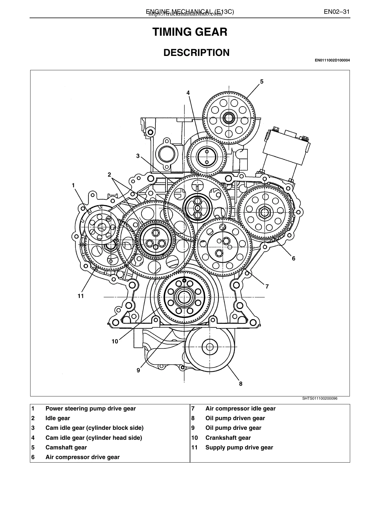
The E13C-TI is a diesel, 4 cycle, vertical, 6 cylinder, in-line overhead camshaft, water-cooled, direct injection engine, turbocharged with intercooler. The manual documents its removal and mounting with the engine hanger part numbers and lifting angles, the disassembly and reassembly of the cylinder head with the head bolt tightening order across No.1 to No.28, the rocker arm assembly and stopper pin arrangement, camshaft gear installation and the timing gear backlash adjustment needed after the cylinder head lower face is ground, crankshaft and main bearing cap installation with the 90 degree plus 45 degree retighten, cylinder liner protrusion measurement, piston ring installation order, piston cooling jet flow test, and flywheel ring gear replacement. The accessory chapters take the alternator, starter, air compressor, engine P.T.O. and engine retarder through the same pattern of data, troubleshooting, component locator, overhaul and inspection so you can bench-service each unit against its own service limits. Turbocharger coverage includes turbine shaft radial and thrust play measurement with the dial gauge and special tool assembly, VGT assembly cylinder stroke checking, and the boost pressure check at maximum speed without load.
Why This Manual Matters for Your E13C
Guessing on a 12.913 litre overhead cam diesel is expensive. A cylinder head bolt sequence done out of order, a bearing cap torqued without the angular stage, a cylinder liner seated without checking protrusion, a valve clearance set to the wrong figure, an injector ID code not entered into the ECU, or a supply pump replaced without resetting the ECU default value – each of these turns a straightforward repair into a repeat job or a damaged engine. The manual gives you the numbers, the order, the special tools and the inspection limits that keep the work correct the first time, and the diagnostic tables let you trace a fault to the actual sensor or circuit instead of replacing parts on suspicion.
IMAGES PREVIEW
Delivery is instant. The PDF downloads immediately after payment, there is no shipping and no waiting on a printed copy, and it opens on a laptop, tablet or phone in the workshop. Print the pages you need for the job in front of you and keep the rest of the Hino E13C workshop manual on the device.
Reviews
There are no reviews yet.