
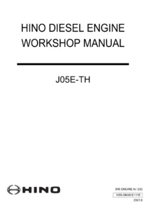
Hino J08E-TM Diesel Engine Workshop Manual PDF
Original price was: $39.95.$23.95Current price is: $23.95.
Complete Hino J08E-TM diesel engine workshop manual covering overhaul, fuel system, EGR, electrical, cooling, lubrication, turbocharger service, failure diagnosis and engine diagnosis codes with standard values and tightening torques.
Description
Hino J08E-TM Diesel Engine Workshop Manual
This Hino J08E-TM Diesel Engine Workshop Manual is the full service and repair documentation for the J08E-TM diesel engine, covering general information, standard values, preparation of tools and parts, engine assembly and disassembly, fuel system, emission control, electrical, intake, engine mechanical, exhaust, cooling, lubrication, starting and charging, turbocharger, failure diagnosis for each engine status and engine diagnosis codes. Every procedure inside this Hino J08E-TM workshop manual is written for the technician working on the engine, with tightening torques, clearances, repair limits, service limits and step-by-step assembly instructions printed alongside the corresponding illustrations.
File Details
- Manual type: Diesel engine workshop manual
- Brand: Hino
- Engine model: J08E-TM
- Language: English
- Page count: 282 pages
- File format: PDF
- Document number: SMTK-E040
Chapters Covered
- General — Warning, How to read this manual, Precautions for work, Tightening of engine bolts and nuts, Tightening of flare nuts and hoses, Taper thread sealant for piping, Assembly of joints and gaskets for piping, Handling of liquid gasket, Failure diagnosis table for each problem, Failure diagnosis procedures, Failure diagnosis using Hino-DX, Connection method of Hino-DX, Chassis number and engine number
- Standard Value — Engine Body, Fuel System, Emission Control, Intake, Engine Mechanical, Exhaust, Cooling, Lubrication, Starting and Charging, Turbocharger
- Parts To Be Prepared — Engine Body, Fuel System, Engine Mechanical, Lubrication, Starting and Charging, Turbocharger, Engine Failure Diagnosis
- Engine Assembly/Disassembly — Inspection Before Service, Measurement of compression pressure, Engine Body removal and installation, Work after installation
- Fuel System — Fuel system diagram, Part layout, Fuel filter drain, Replacement of fuel filter element, Replacement of supply pump, Inspection of supply pump, Replacement of injector, Inspection of injector, Replacement of common rail, Inspection of common rail
- Emission Control — EGR part layout, Overhaul of EGR valve and EGR cooler
- Electrical — Part layout, Layout of components, Inspection of components, Installation of starter, Removal of alternator, Installation of alternator
- Intake — Intake manifold part layout and replacement
- Engine Mechanical — Cylinder Head, Cylinder Block, Timing Gear Cover and Flywheel Housing, Main Moving Parts, Camshaft and Idle Gear, Valve System
- Exhaust — Exhaust Manifold part layout and replacement
- Cooling — Cooling system drawing, Part layout, Replacement of thermostat case, Inspection of thermostat, Replacement of coolant pump
- Lubrication — Oil Cooler, Oil Filter and Oil Pump, Oil Pan, Inspection of lubrication status
- Starting and Charging — Starter disassembly, inspection and assembly, Alternator (60A) disassembly, inspection and assembly
- Turbocharger — Setup layout, Part layout, Inspection, Replacement
- Failure Diagnosis For Each Engine Status — Engine mechanical, Alternator, Starter, Turbocharger
- Engine Diagnosis Code — Engine ECU, Precautions, System block diagram, Inspection, Connection method of Hino-DX, Table of failure code, Signal check harness, Computer pin arrangement
Taken as a whole, this document gives a technician the complete service picture for the J08E-TM rather than a scattered set of instructions. The early chapters establish how the manual is organised, how tightening torques and flare nut torques are applied, how liquid gasket and taper thread sealant are handled, and how Hino-DX is connected for diagnosis. The middle chapters move into the hardware itself — cylinder head and cylinder block overhaul, cylinder liner replacement and protrusion measurement, cooling jet inspection and adjustment, piston and connecting rod work, crankshaft and main bearing measurement, camshaft and idle gear timing, valve system adjustment and timing gear backlash checks. The later chapters close the loop with fuel system component replacement, EGR valve and EGR cooler overhaul, starter and alternator service, turbocharger inspection, and finally the diagnostic code tables with step-by-step troubleshooting for each stored fault.
Standard Values and Service Limits
A dedicated standard value chapter consolidates the numbers a technician needs before starting work, so measurements can be checked against the correct figure without hunting through individual procedures. Compression pressure standard values and service limits are listed for the engine body and again for engine mechanical work, along with the maximum permitted difference between cylinders. Valve clearance is given for a cold engine on both intake and exhaust sides. Cylinder liner protrusion, cylinder liner flange width, cylinder block flange width and cylinder block inner diameter are tabulated by grade. Piston outer diameter, piston clearance, piston ring joint clearance, ring width and ring groove dimensions are grouped together with their repair limits and service limits, and the same structure is repeated for crankshaft crank pin and journal dimensions, connecting rod oil clearance, main bearing thickness and crankshaft end play.
Camshaft cam height, cam lift, journal diameter, bearing oil clearance and camshaft runout are listed with replacement thresholds. Valve stem diameter, valve guide inner diameter, valve sink and valve spring free length and squareness follow in the same format. Timing gear backlash values are provided between every meshing pair — crank to main idle, main idle to pump drive idle, pump drive idle to pump drive, main idle to sub-idle, sub-idle to oil pump, sub-idle to cam idle and cam idle to cam — each with a service limit. Flatness under the cylinder head and above the cylinder block, flywheel surface runout and the replacement limits for camshaft gear mounting bolts, bearing cap bolts, connecting rod bolts and head bolts are also included.
Tightening Torque Reference
Torque tables appear both in the general chapter and in each system chapter, so the correct figure is available at the point of assembly. General standard bolts are listed by screw diameter and pitch for 7T and 9T seat bolts and for 4T, 7T and 9T washer bolts, with coarse and fine thread variants separated. The general chapter also documents the plastic region tightening method used on cylinder head bolts, crankshaft main bearing cap bolts and connecting rod bearing cap bolts, including the angle steps and the requirement to measure bolt length before assembly.
System-specific torque tables cover the engine mounting nut, starter and alternator terminals, oil pan drain cock, radiator hose band and fuel filter air bleeding plug. The fuel system chapter lists injector clamp, supply pump bearing holder case, coupling flange mounting nut, injector harness and fuel filter air bleeding bolt torques. Emission control gives EGR pipe, EGR valve, EGR cooler and EGR cooler to exhaust manifold torques. Engine mechanical provides the full engine torque set including crankshaft pulley, head cover, camshaft bearing cap, camshaft gear, rocker arm support, head bolts, main bearing cap, connecting rod cap, flywheel, flywheel housing and rear end plate. Cooling, lubrication, starting and charging, and turbocharger chapters each carry their own torque tables.
Diagnostic Coverage
The failure diagnosis material is split into two distinct approaches. The first is a status-based diagnosis table organised by symptom, covering engine overheat from coolant, radiator, compression pressure and lubrication causes; large engine oil consumption from piston, cylinder liner, piston ring, valve and valve guide causes; piston seizure in operation and from lubrication unit faults; insufficient engine power from air cleaner, fuel unit and compression causes; faulty engine start from electrical, air cleaner, fuel unit and lubrication causes; and abnormal noise from alternator and belt. Each row pairs the cause with the corrective action.
The second approach is code-based. The manual explains that a failure code is displayed on the multiple display of the gauge cluster, how past failures are deleted using Hino-DX on a PC, and how the cluster gauge past failure memory is cleared with the buzzer stop switch and job mode selecting switch. Troubleshooting is then presented code by code, with measurement steps, standard values, OK and NG branches, and clear indications of when a component must be replaced. The engine diagnosis code chapter provides the failure code table linking DTC codes to diagnosis monitor codes and estimated failure causes, plus a signal check harness that interrupts between the vehicle harness and the ECU so a tester rod can be placed on the connector while power is supplied.
Illustrations and Part Layouts
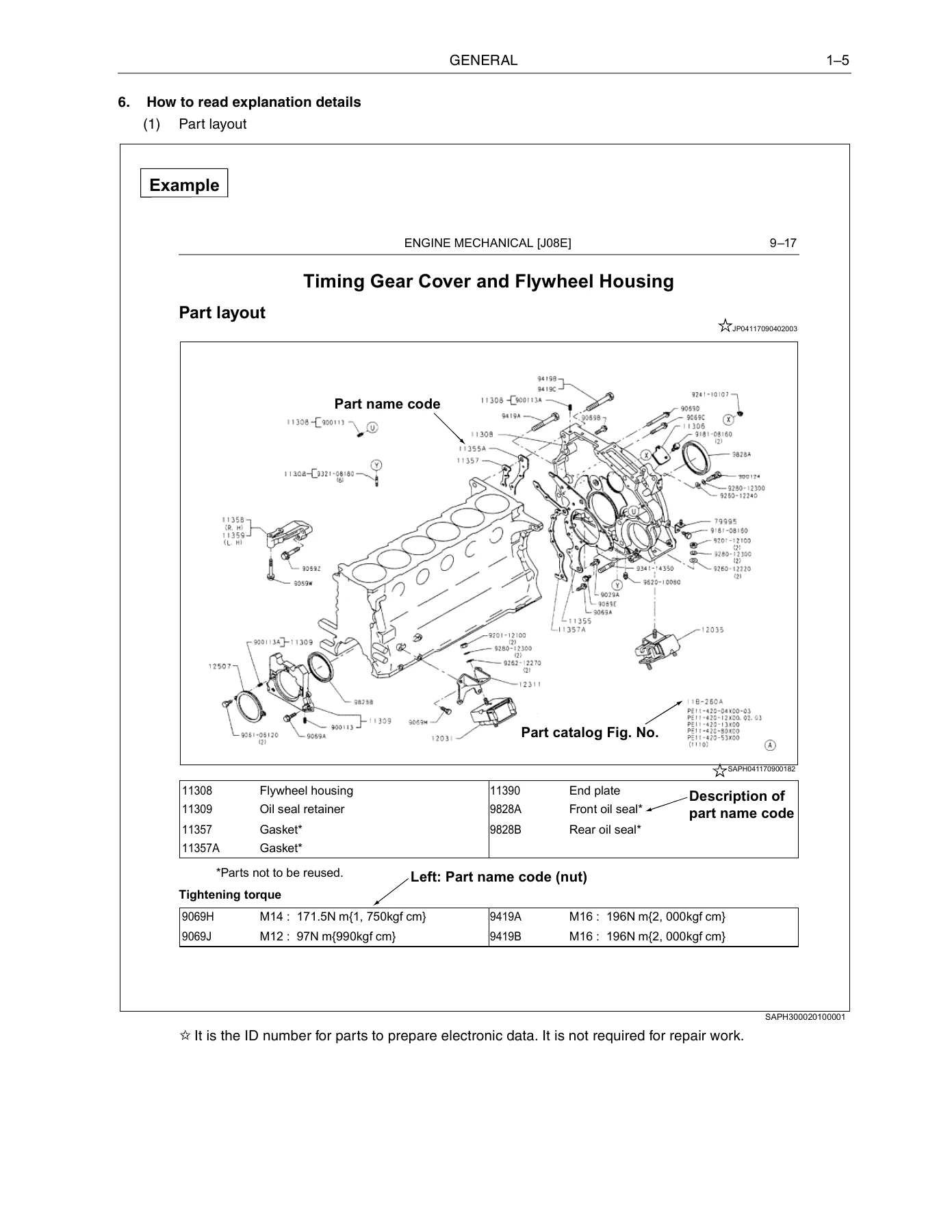
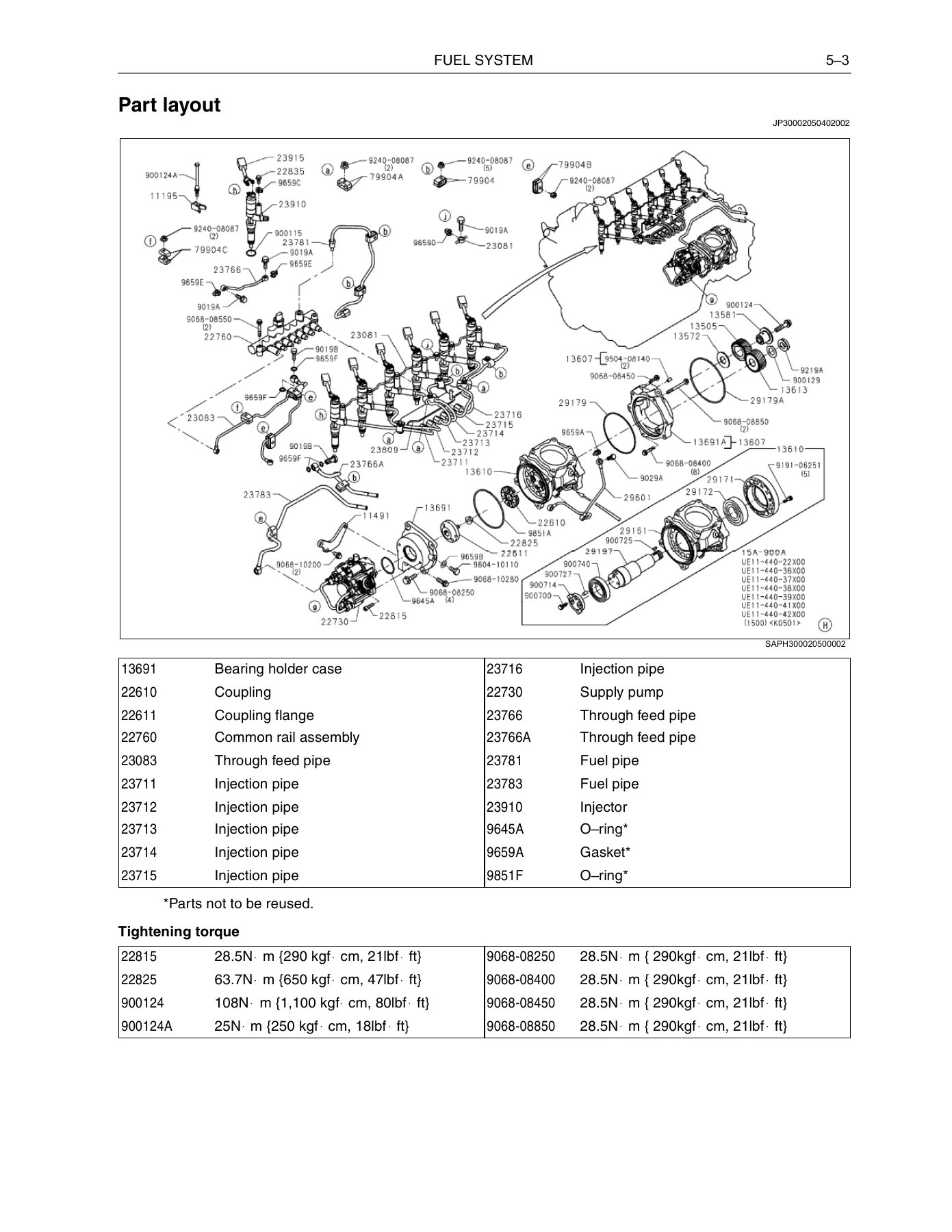
Part layouts are reproduced from the parts catalogue illustrations, with part name codes, part numbers and tightening torque values listed in the accompanying tables beneath each exploded view. Major assemblies are drawn apart so the assembly order and the position of every bolt, gasket, O-ring and seal are visible before disassembly begins. The manual notes that some areas do not show an exploded view and that the parts catalogue should be used to confirm illustrations and part numbers when ordering replacement components. System drawings are also included for the fuel circuit, the cooling circuit and the lubrication circuit, showing flow direction through the feed pipe, common rail, injector, leakage pipe, overflow pipe and through feed pipe, and through the radiator, thermostat, coolant pump, oil cooler, EGR cooler, turbocharger and heater.
What This Manual Lets You Do
With this Hino J08E-TM diesel engine workshop manual on hand, you can carry out a compression test and interpret the result against the published standard and service limit, remove and reinstall the engine, replace the cylinder head and head gasket using the correct bolt loosening and tightening sequence, replace cylinder liners with the matching identification mark and verify flange protrusion, inspect and adjust the cooling jets, remove and refit pistons and connecting rods with the correct ring joint spacing, measure and regrind or replace the crankshaft using undersize bearings, remove and install the camshaft and time the idle gears, adjust valve clearance using the crosshead procedure, and service the fuel system including supply pump replacement with the correct compression top dead centre alignment and the injector correction value entry that follows it.
It also covers what many owners and technicians need most — diagnosing a fault instead of replacing parts. The symptom tables and the code tables together let you move from a reported problem to a specific component, measure it against a stated value, and decide whether to repair, replace or adjust. Because the manual lists tightening torques, clearances and service limits in the same place as the procedure that needs them, there is no guesswork about how far a bolt should be turned or how much wear is acceptable.
Delivery is instant. The Hino J08E-TM workshop manual is supplied as a PDF that opens on any device — laptop, tablet or phone — and can be printed page by page for use in the workshop, so the relevant torque table or exploded view can sit beside the engine rather than on a screen across the bay.
IMAGES PREVIEW
Reviews
There are no reviews yet.