

DEUTZ TD 3.6 L4 & TCD 3.6 L4 Stage IV / Tier 4 Workshop Manual 0312 4399 PDF
Original price was: $44.95.$24.95Current price is: $24.95.
Detailed 404-page DEUTZ Workshop Manual for TD 3.6 L4 and TCD 3.6 L4 industrial engines meeting EU Stage IV / US EPA Tier 4 requirements. Covers workshop job-card procedures for engine mechanical work, lubrication, common-rail fuel equipment, cooling, turbocharging, EGR, exhaust aftertreatment, electrical components, accessories, testing, tightening data, and special tools.
Description
DEUTZ TD 3.6 L4 & TCD 3.6 L4 Stage IV / Tier 4 Workshop Manual 0312 4399 PDF
The DEUTZ TD 3.6 L4 & TCD 3.6 L4 Stage IV / Tier 4 Workshop Manual 0312 4399 PDF is a competence level 2 workshop reference for TD 3.6 L4 and TCD 3.6 L4 industrial engines. It is structured around detailed workshop job cards rather than general operating instructions, giving technicians illustrated repair workflows, required tools, component positions, assembly precautions, test and setting data, and tightening specifications wherever the individual procedure requires them. Coverage includes engine mechanical components, common-rail fuel equipment, lubrication and cooling systems, turbocharging and charge air, exhaust gas recirculation, electrical components, and the EU Stage IV / US EPA Tier 4 exhaust aftertreatment equipment shown in the manual.
File Details
- Manual type: Workshop Manual, competence level 2
- Brand: DEUTZ
- Engine models: TD 3.6 L4 and TCD 3.6 L4
- Application: Industry
- Emissions coverage: EU Stage IV / US EPA Tier 4
- Language: English
- Page count: 404 pages
- File format: PDF
- Order number: 0312 4399 en
- Edition: 1st edition, 01/2015
Workshop Job-Card Format
This DEUTZ TD 3.6 L4 and TCD 3.6 L4 workshop manual is built around repair job cards. The manual explains that its W job cards document standard repairs to the engine and its components, with the necessary conventional and special tools identified for the work. Individual cards combine component illustrations with removal and installation sequences, warnings, auxiliary materials, references to related modules, and technical data. Symbols identify test and setting values and tightening specifications so that critical information is placed alongside the procedure where it is needed.
The workshop material assumes knowledge of the corresponding operating instructions. The manual itself distinguishes the workshop job cards from the separate operation manual: routine operating information, general maintenance schedules, operating media, basic fault information, transport and storage, and broader technical data belong to that companion documentation. This 0312 4399 manual concentrates on repairs and component-level workshop work requiring suitable equipment, special tools where specified, and qualified personnel.
Chapters Covered
- 1 Foreword
- 2 General
- 3 Safety instructions / User information
- 3.1 General
- 3.2 Regulations
- 3.3 Operation manual and workshop manual
- 3.4 Job cards
- 3.5 Picture symbols explanation
- 4 Chapter not assigned
- 5 Job card overview
- 5.1 Sorted alphabetically
- 5.2 Sorted numerically
- 6 Job cards
- 7 Chapter not assigned
- 8 Special tools
The main body is therefore much more extensive than the short top-level contents list suggests. Chapter 6 contains the individual repair cards across the engine and its supporting systems, while Chapter 8 provides a dedicated special-tool reference with tool numbers and intended uses. The job-card overview allows procedures to be found by activity or by job-card number.
Engine Mechanical, Lubrication and Drive Components
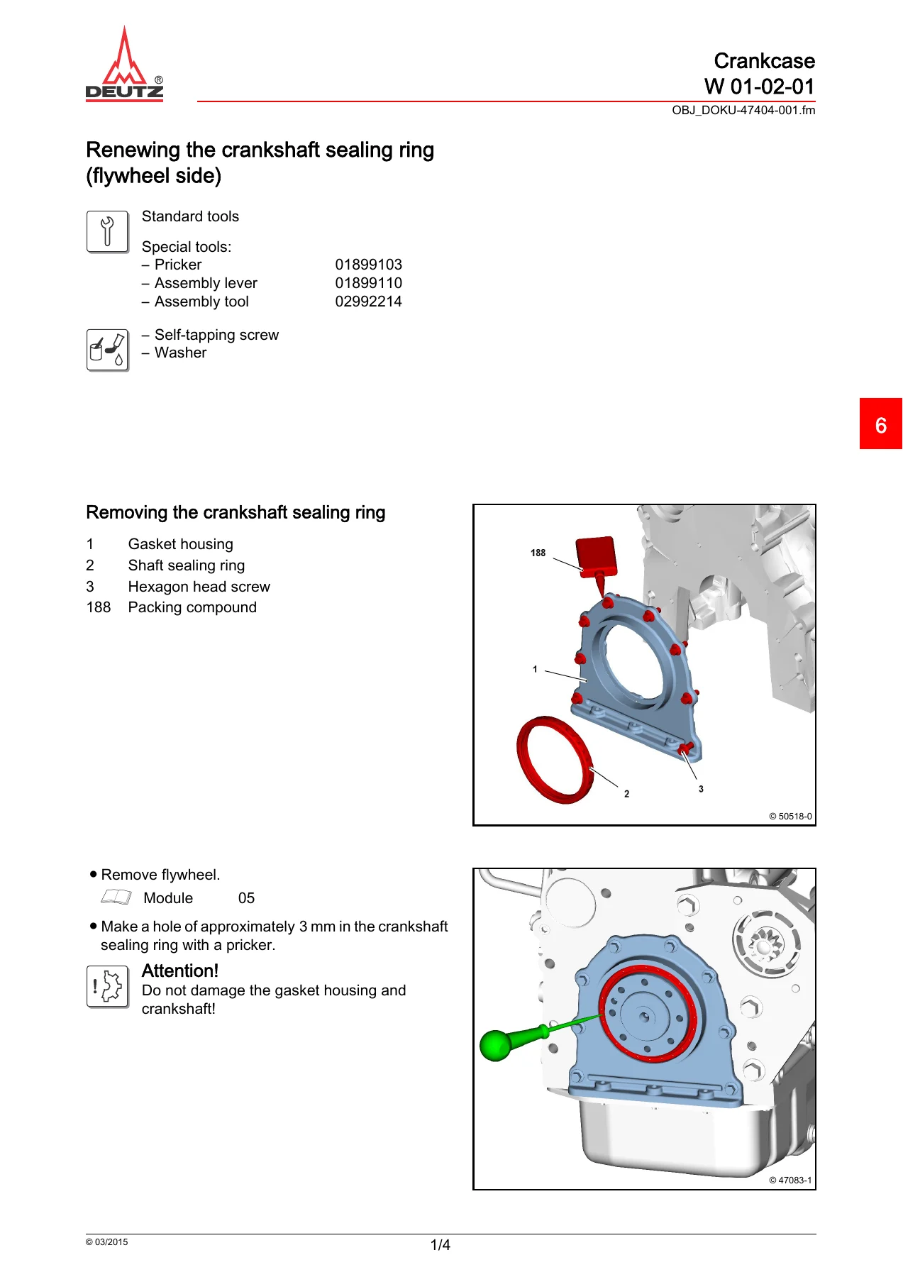
Mechanical workshop coverage starts with crankcase-related work such as renewing the crankshaft sealing ring on the flywheel side, removing and installing the gasket housing and transfer line, servicing the oil pressure regulating valve, and working with crankcase closing parts and the breather. Lubrication procedures include removal and installation of the lubricating oil pan, oil suction pipe, oil cooler, lubricating oil filter arrangements, oil lines, and the turbocharger lubricating oil supply and return lines.
The manual also addresses the crankshaft pulley and V-ribbed pulley installation, sensor wheel, flywheel, opposite-side crankshaft sealing ring, gearcase components, connection housing, belt tensioner, generator-related parts, engine mountings, starter, coolant compressor, and hydraulic pump drive. Many of these procedures include illustrated fastening sequences and dedicated tightening-data pages. For example, the crankshaft pulley procedure uses staged tightening, while the flywheel procedure specifies its own multi-stage sequence and renewal precautions for fasteners.
Fuel System, Injectors and Diagnostic Work
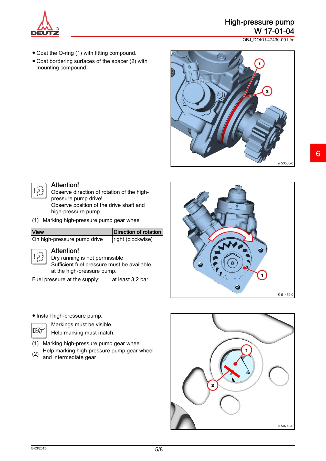
A substantial part of the DEUTZ TD 3.6 L4 & TCD 3.6 L4 Workshop Manual covers the high-pressure fuel system. Job cards show removal and installation of the high-pressure pump, injector, fuel rail, high-pressure and injection lines, fuel return line, fuel filter, fuel pre-filter, and supply pump. Because these components operate under high pressure, the procedures repeatedly emphasize depressurization, cleanliness, sealing open connections, correct line positioning, and replacement of specified high-pressure lines after dismantling.
The injector section includes work associated with the 1600 bar injection-system configuration shown in the manual. It explains injector-to-cylinder assignment through the IMA code and references SerDia 2010 when injector data and correction values must be handled. Fuel-rail procedures cover the rail pressure sensor and pressure limiting valve as well as the prescribed staged tightening of injection and high-pressure line union nuts.
Diagnostic material includes a compression-pressure check performed with the injectors removed. The manual gives a reference range of 25 – 30 bar (2500 – 3000 kPa) and instructs that the cylinders be compared with one another; a deviation greater than 15% is identified as a reason to determine the cause in the affected cylinder unit. The procedure includes the required compression tester, adapters, fuel handling steps, battery operations, and reassembly sequence.
Cooling, Charge Air, Turbocharger and EGR
Cooling-system workshop cards cover the coolant pump, its drive components and pulleys, thermostat housing, thermostat testing, coolant pipes, and associated connections. The thermostat test gives an opening-start range of 86 – 90 °C and a minimum stroke of 9 mm at a test temperature of 99 – 102 °C. The procedure describes the controlled water-bath test rather than simply listing the values.
Air and exhaust work includes the charge air line, charge air manifold, turbocharger intake nozzle, exhaust line, turbocharger and its lubrication connections. Exhaust gas recirculation receives extensive component-level treatment, including the flutter valve, EGR cooler, exhaust gas return valve, exhaust gas return pipe, Venturi tube, temperature sensor, pressure sensor, holders, coolant connections and related hoses. The job cards show sealing requirements, installation orientation, cable handling, component inspection, replacement of specified O-rings and gaskets, and tightening values.
EU Stage IV / US EPA Tier 4 Exhaust Aftertreatment
The emissions-system material is especially useful for technicians working on the Stage IV / Tier 4 configuration identified on the manual cover. Exhaust gas treatment job cards include removal and installation information for NOx sensors, SCR exhaust back-pressure sensing, the SCR dosing device, temperature sensing ahead of the diesel oxidation catalyst, exhaust-system compensator components, the DOC/DPF catalytic converter assembly, SCR catalytic converter, SCR supply pump, SCR tank, coolant line, console and mixing pipe.
These sections also carry system-specific safety and cleanliness instructions. The manual discusses filter-regeneration precautions before service work, SCR lag time that can be application-dependent, correct NOx-sensor assignment, cable routing, replacement of V-band clips and gaskets where specified, component flow direction, and the need to follow the equipment manufacturer’s installation arrangement where the exhaust installation is application-dependent.
Electrical, Sensors and Workshop Tools
Electrical and sensing coverage includes the charge-air pressure/temperature sensor, crankshaft and camshaft impulse transmitters, oil-pressure transmitter, cable harness fastening components, relay installation, glow plugs and starter work. The manual also shows the use of the turning gear / locking device for rotating and locking the crankshaft during procedures that require a defined position.
Chapter 8 consolidates the specialist equipment called out in the job cards. It identifies items such as the compression pressure tester, V-belt tension measuring device, rotation-angle disc, crankshaft-seal tools, spring-band pliers, injector tools, force multiplier, fuel-system plugs and caps, NOx-sensor claw wrench, turning gear / locking device, counter support, high-pressure-line wrench and the SerDia 2010 diagnostic tool. Tool numbers and intended workshop uses are provided, making it easier to match a procedure to the equipment called for by that job card.
Illustrated Procedures and Technical Data
The 404 pages contain numerous exploded component views, highlighted installation illustrations, fastening sequences and technical-data sheets. Procedures routinely identify what must be removed first, where new seals or fasteners are required, which auxiliary material is specified, how a part must be oriented, and what inspection should be completed before installation. This is particularly valuable for work where a seemingly small installation detail matters, such as fuel-line alignment, crankshaft-seal depth, gasket positioning, staged angle tightening, EGR sealing, or sensor cable routing.
Rather than relying on a single general torque chart, many job cards end with tightening specifications directly tied to the component being serviced. Testing and setting values are likewise included with the appropriate jobs, as seen in the compression and thermostat checks. This structure helps keep the repair sequence, tooling and technical values together while carrying out the work.
Repair with the Correct TD 3.6 L4 / TCD 3.6 L4 Workshop Information
The DEUTZ TD 3.6 L4 & TCD 3.6 L4 Stage IV / Tier 4 Workshop Manual 0312 4399 PDF supports detailed component removal, installation, testing and reassembly across the engine mechanical, lubrication, fuel, cooling, charge-air, turbocharger, EGR, electrical and exhaust-aftertreatment systems covered by its job cards. Having the specified workflow, special-tool references, tightening data, test values, sealing instructions and installation precautions available at the job helps reduce guesswork during technical repair work.
Delivered as an instant PDF after purchase, there is no physical book to ship or wait for. Open the manual on a computer, tablet or other PDF-capable device, keep it available at the workbench, and print the pages needed for a particular repair or inspection.
IMAGES PREVIEW
Reviews
There are no reviews yet.