★ TRUSTED BY 321,897+ PROFESSIONALS WORLDWIDE
🏢
Trusted Business
Verified & Licensed
🛡️
Virus Free Files
100% Safe Downloads
🔒
Secure Payment
SSL Protected
⚡
Instant Delivery
Available Immediately
Sale!

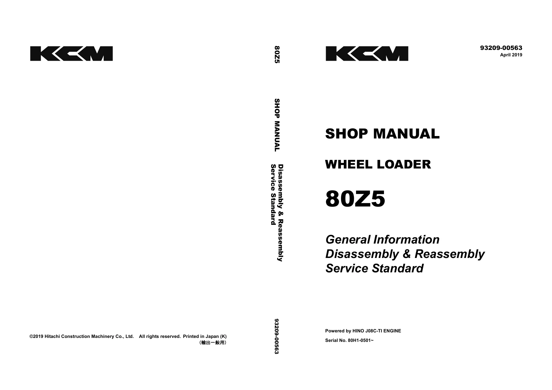
Hitachi 80Z5 Wheel Loader Shop Manual – Disassembly, Reassembly & Service Standards (93209-00563)

Original price was: $39.95.Current price is: $24.95.

310-page Hitachi 80Z5 wheel loader shop manual covering complete disassembly, reassembly, and service standards for chassis, power train, torque converter/transmission, hydraulics, brakes, and operator station. Document 93209-00563, April 2019.

⚡
Instant PDF Download
Available immediately
💾
Save to Your Device
Download & keep forever
🛡️
Antivirus Scanned
100% virus-free
🌍
Trusted Worldwide
175,000+ customers

Description

Hitachi 80Z5 Wheel Loader Shop Manual

This Hitachi 80Z5 Wheel Loader Shop Manual is the complete disassembly, reassembly, and service standard reference for the 80Z5 wheel loader. Published under document number 93209-00563 (April 2019), it provides the procedures, tightening torques, clearance values, and component weights a service technician needs to strip down and rebuild the machine correctly. Every major group is covered with both a disassembly/reassembly chapter and a matching service standard chapter, so the procedure and the acceptance criteria sit side by side in the same manual.

File Details

  • Manual type: Shop Manual – Disassembly & Reassembly and Service Standard
  • Brand: Hitachi
  • Model: 80Z5 Wheel Loader
  • Document number: 93209-00563
  • Date: April 2019
  • Language: English
  • Page count: 310 pages
  • Format: PDF

Note: for the engine itself, the manual directs the technician to the engine manufacturer’s own shop manual. This document covers the machine-side systems around the engine.

Chapters Covered

The contents are organized into paired disassembly/reassembly and service standard groups:

  • 00 General Information
    • Symbols
    • Weight of Main Components
    • Bolt Tightening Torque
    • Hose Band Tightening Torque
    • Liquid Gasket and Screw Lock Agent
    • Cautions Regarding Welding Repair Service
    • Cautions Regarding Handling of Bearing
    • Applying and Storing Articulation Stopper
  • 14 Disassembly & Reassembly Chassis Group
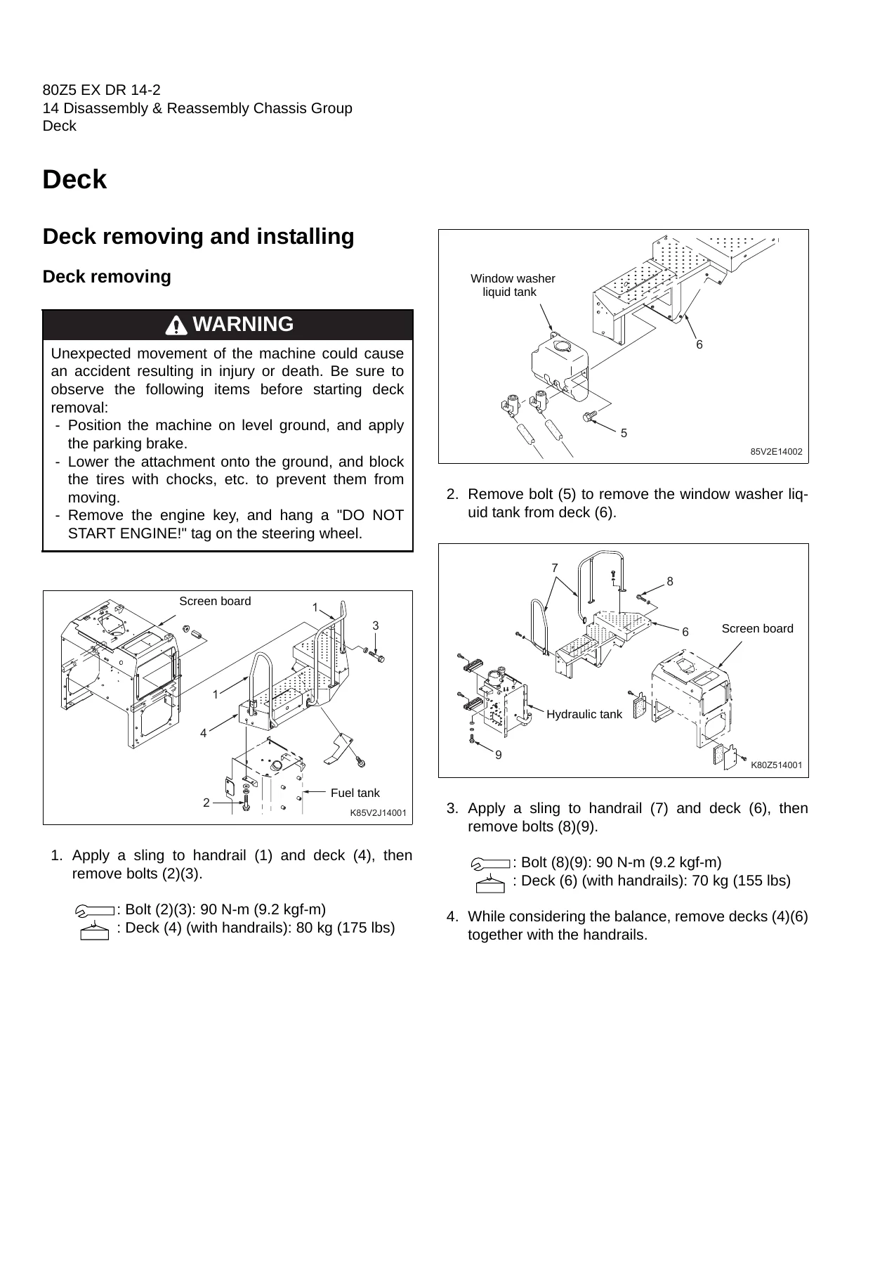
    • Deck, Fuel Tank, Hydraulic Tank
    • Engine Room, Cab, Floor Board
    • Boom, Center Pin (Upper / Lower)
  • 15 Service Standard Chassis Group
    • Linkage, Linkage Pin Standard Clearance Values
    • Liner Clearance Adjustment
    • Center Pin (shim adjustment, bearing cover, lower bearing outer ring)
    • Attachment Leveler (adjustable angle)
  • 24 Disassembly & Reassembly Power Group
    • Power Line, Radiator, Fan, Engine
    • Propeller Shaft (second / third)
    • Air Cleaner, Muffler
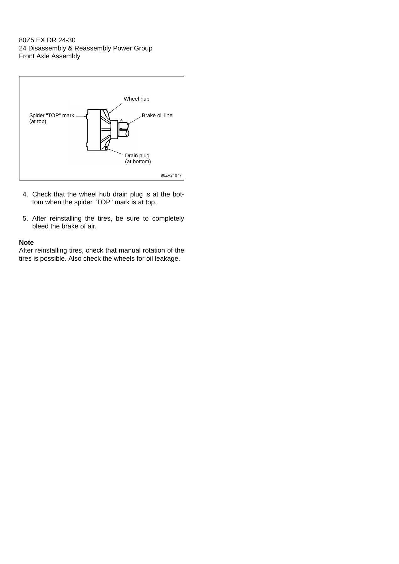
    • Front Axle Assembly, Internal Gear Hub, Spider Assembly, Special Tools
    • Rear Axle Assembly, Axle Support, Differential Assembly
  • 25 Service Standard Power Group
    • Propeller Shaft Service Standard
    • Axle and Differential Service Standard
  • 34 Disassembly & Reassembly Torque Converter and Transmission Group
    • Torque Converter and Transmission Assembly
    • Torque Converter Assembly
    • Transmission Assembly
    • Forward/Reverse, 1st/3rd, 2nd, and 4th Speed Clutch Packs
    • Control Valve Assembly
  • 35 Service Standard Torque Converter and Transmission Group
    • Transmission Assembly, Control Valve, Gear Pump
    • Clutch Plate Thickness / Piston Stroke
    • Clutch Oil Pressure
  • 44 Disassembly & Reassembly Hydraulic Group
    • Hydraulic Pump Assembly
    • Boom, Bucket and Steering Cylinders
    • Pilot Valve, Multiple Control Valve
    • Orbitrol®, Steering Valve, Stop Valve, Fan Motor
  • 45 Service Standard Hydraulic Group
    • Hydraulic Cylinder, Pilot Valve, Steering Valve
  • 54 Disassembly & Reassembly Brake Group
    • Unloader Valve, Manifold Valve Assembly
    • Accumulator (including nitrogen gas charging)
    • Brake Valve, Service Brake
    • Parking Brake Actuator, Parking Brake
  • 55 Service Standard Brake Group
    • Brake Valve, Service Brake, Parking Brake
  • 74 Disassembly & Reassembly Operator Station Group
    • Air Conditioner
  • 75 Service Standard Operator Station Group
    • Air Conditioner (periodic inspection/servicing, tightening torques)

What This Hitachi 80Z5 Shop Manual Gives You

This is a working shop manual rather than an operator’s handbook. Each mechanical group is presented twice: once as a step-by-step removal and installation or disassembly and reassembly procedure, and once as a service standard table that tells you what to measure and what to compare it against. The result is that when you pull an axle shaft, a center pin, a clutch pack, or a hydraulic cylinder, you already have the standard clearance, wear limit, preload figure, and tightening torque in front of you.

The general information chapter sets the ground rules for the whole document. It includes the weight of every major component – buckets, boom, levers, engine room, tanks, chassis sections, axles, differential, hydraulic components, tires, and battery – plus metric, unified, and flanged hexagon bolt tightening torque tables, hose band torque, and the Loctite® and Three Bond liquid gasket and screw lock agent references used in the machine. It also covers bearing handling and installation, welding repair precautions, and the articulation stopper procedure that must be applied before any work in the articulation area.

In the chassis group, the manual walks through removing and installing the deck, fuel tank, hydraulic tank, engine room, cab, and floor board, then the boom and the upper and lower center pins. The matching service standard chapter gives the linkage pin standard clearance values for all eleven joint sections (attachment-to-boom, boom-to-lever, boom-to-boom cylinder, front chassis-to-boom, and so on), the liner clearance adjustment procedure, and the center pin shim adjustment and bearing cover installation.

Complete PDF Bookmark Tree

Complete Bookmarks

The complete bookmarks in the “Hitachi 80Z5 Wheel Loader Shop Manual – Disassembly, Reassembly & Service Standards (93209-00563)” are as follows:

80Z5(EX-D&R).pdf
Forewordp. 2
Safety precautionsp. 3
Safety Symbolsp. 4
CONTENTSp. 6
00 General Informationp. 12
Symbolsp. 13
Weight of Main Componentsp. 14
Bolt Tightening Torquep. 15
Hose Band Tightening Torquep. 19
Liquid Gasket and Screw Lock Agentp. 20
Cautions regarding parts removalp. 20
Cautions regarding reassemblyp. 20
Screw lock agent application procedurep. 21
How to wind a seal tapep. 21
Cautions Regarding Welding Repair Servicep. 22
Cautions Regarding Handling of Bearingp. 24
Bearing installation cautionsp. 24
Interference fits for a bearingp. 24
Bearing operation test after installationp. 25
Bearing removal cautionsp. 25
Applying and Storing Articulation Stopperp. 26
Applying articulation stopperp. 26
Storing articulation stopperp. 26
14 Disassembly & Reassembly Chassis Groupp. 28
Deckp. 29
Deck removing and installingp. 29
Deck removingp. 29
Deck installingp. 30
Fuel Tankp. 31
Fuel tank removing and installingp. 31
Fuel tank removingp. 31
Fuel tank installingp. 31
Fuel tank installation cautionsp. 31
Hydraulic Tankp. 32
Hydraulic tank removing and installingp. 32
Hydraulic tank removingp. 32
Hydraulic tank installingp. 33
Hydraulic tank installation cautionsp. 33
Engine Roomp. 34
Engine room removing and installingp. 34
Engine room removingp. 34
Engine room installingp. 36
Engine room installation cautionsp. 36
Cabp. 37
Cab removing and installingp. 37
Cab removingp. 37
Cab installingp. 38
Floor Boardp. 39
Floor board removing and installingp. 39
Floor board removingp. 39
Floor board installingp. 41
Floor board installation cautionsp. 41
Boomp. 42
Boom removing and installingp. 42
Boom removingp. 42
Boom installingp. 44
Boom installation cautionsp. 44
Center Pinp. 45
Upper center pinp. 45
Center pin shim adjustmentp. 45
Lower center pinp. 46
Center pin removing and installingp. 47
Center pin removingp. 47
Center pin installingp. 50
Center pin installation cautionsp. 50
15 Service Standard Chassis Groupp. 52
Linkagep. 53
Linkage Pin Standard Clearance Valuesp. 54
Liner clearance adjustmentp. 55
Center Pinp. 56
Center pin shim adjustmentp. 56
Bearing cover installingp. 56
Lower center pin bearing outer ring installingp. 57
Attachment Levelerp. 58
Attachment levelerp. 59
Attachment leveler adjustable anglep. 59
24 Disassembly & Reassembly Power Groupp. 60
Power Linep. 61
Power line tightening torquep. 61
Radiatorp. 62
Radiator tightening torquep. 62
Radiator removing and installingp. 63
Radiator removingp. 63
Radiator installingp. 65
Radiator installation cautionsp. 65
Fanp. 66
Fan removing and installingp. 66
Fan removingp. 66
Fan installingp. 67
Fan installation cautionsp. 67
Enginep. 68
Engine removing and installingp. 68
Engine removingp. 68
Engine installingp. 70
Engine installation cautionsp. 70
Propeller Shaftp. 71
Propeller shaft removing and installingp. 71
Second propeller shaft removingp. 71
Third propeller shaft removingp. 72
Propeller shaft installingp. 72
Propeller shaft installation cautionsp. 72
Air Cleanerp. 73
Air cleaner removing and installingp. 73
Air cleaner removingp. 73
Air cleaner installingp. 74
Air cleaner installation cautionsp. 74
Mufflerp. 75
Muffler removing and installingp. 75
Muffler removingp. 75
Muffler installingp. 75
Muffler installation cautionsp. 75
Front Axle Assemblyp. 76
Front axle assembly tightening torquep. 76
Axle nut tightening procedurep. 77
Floating seal installationp. 77
Front axle assembly removing and installingp. 78
Front axle assembly removingp. 78
Front axle assembly installingp. 79
Front axle assembly installation cautionsp. 80
Service brake air bleeding procedurep. 80
Front axle disassembling and assemblingp. 81
Front axle disassemblingp. 81
Front axle assemblingp. 84
Front axle assembly cautionsp. 85
Floating seal installationp. 85
Internal gear hub installationp. 87
Axle nut tighteningp. 87
Brake adjustmentp. 88
Internal Gear Hubp. 90
Internal gear hub disassembling and assemblingp. 90
Internal gear hub disassemblingp. 90
Internal gear hub assemblingp. 91
Internal gear hub assembly cautionsp. 92
Spider Assemblyp. 93
Spider assembly disassembling and assemblingp. 93
Spider assembly disassemblingp. 93
Spider assembly assemblingp. 94
Spider assembly assembly cautionsp. 94
Special Toolp. 95
Special tool for axlep. 95
Rear Axle Assemblyp. 100
Rear axle assembly tightening torquep. 100
Axle nut tightening procedurep. 101
Floating seal installationp. 101
Rear axle assembly removing and installingp. 102
Rear axle assembly removingp. 102
Rear axle assembly installingp. 104
Rear axle disassembling and assemblingp. 104
Axle Supportp. 105
Axle support tightening torquep. 105
Axle support disassembling and assemblingp. 106
Axle support disassemblingp. 106
Axle support assemblingp. 106
Axle support assembly cautionsp. 107
Differential Assemblyp. 108
Differential assembly removing and installingp. 108
Differential assembly removingp. 108
Differential assembly installingp. 109
Differential assembly installation cautionsp. 109
Differential assembly disassembling and assemblingp. 110
Front differential tightening torquep. 110
Rear differential tightening torquep. 111
Differential assembly disassemblingp. 112
Differential assembly assemblingp. 116
25 Service Standard Power Groupp. 124
Propeller Shaft Service Standardp. 125
Axle and Differential Service Standardp. 126
Axle groupp. 126
Differentialp. 127
34 Disassembly & Reassembly Torque Converter and Transmission Groupp. 128
Torque Converter and Transmission Assemblyp. 129
Torque converter and transmission assembly tightening torquep. 129
Torque converter and transmission assembly removing and installingp. 130
Torque converter and transmission assembly removingp. 130
Torque converter and transmission assembly installingp. 135
Transmission assembly installation cautionsp. 136
Joint between the torque converter and the enginep. 136
Transmission assembly operation checkp. 136
Torque Converter Assemblyp. 138
Torque converter assembly bolt tightening torquep. 138
Torque converter assembly disassembling and assemblingp. 139
Torque converter assembly disassemblingp. 139
Torque converter assembly assemblingp. 142
Transmission Assemblyp. 146
Transmission assembly bolt tightening torquep. 146
Transmission assembly disassembling and assemblingp. 148
Transmission assembly disassemblingp. 148
Transmission assembly assemblingp. 152
Transmission Forward/Reverse Clutch Packp. 159
Forward/reverse clutch pack disassembling and assemblingp. 159
Forward/reverse clutch pack disassemblingp. 159
Forward/reverse clutch pack assemblingp. 161
Forward/reverse clutch pack assembly cautionsp. 161
Transmission 1st/3rd Speed Clutch Packp. 162
Transmission 1st/3rd speed clutch pack disassembling and assemblingp. 162
Transmission 1st/3rd speed clutch pack disassemblingp. 162
Transmission 1st/3rd speed clutch pack assemblingp. 163
Transmission 1st/3rd speed clutch pack assembly cautionsp. 163
Transmission 2nd Speed Clutch Packp. 164
Transmission 2nd speed clutch pack disassembling and assemblingp. 164
Transmission 2nd speed clutch pack disassemblingp. 164
Transmission 2nd speed clutch pack assemblingp. 165
Transmission 2nd speed clutch pack assembly cautionsp. 165
Transmission 4th Speed Clutch Packp. 166
Transmission 4th speed clutch pack disassembling and assemblingp. 166
Transmission 4th speed clutch pack disassemblingp. 166
Transmission 4th speed clutch pack assemblingp. 167
Transmission 4th speed clutch pack assembly cautionsp. 168
Control Valve Assemblyp. 169
Control valve tightening torquep. 169
Control valve removing and installingp. 170
Control valve removingp. 170
Control valve installation cautionsp. 171
Control valve disassembling and assemblingp. 172
Control valve disassemblingp. 172
Control valve assemblingp. 173
Control valve assembly cautionsp. 173
35 Service Standard Torque Converter and Transmission Groupp. 174
Transmission Assemblyp. 175
Control Valvep. 176
Gear Pumpp. 178
Gear pump specificationsp. 178
Clutch Plate Thickness/Piston Strokep. 179
Clutch platep. 180
Piston strokep. 180
Clutch Oil Pressurep. 181
Clutch oil pressure standard valuep. 181
44 Disassembly & Reassembly Hydraulic Groupp. 182
Hydraulic Parts Removal and Installation Warningp. 183
Hydraulic Parts Disassembly and Assembly Cautionsp. 184
Hydraulic parts disassembly cautionsp. 184
Hydraulic parts assembly cautionsp. 184
Hydraulic Pump Assemblyp. 185
Hydraulic pump assembly removing and installingp. 185
Hydraulic pump assembly removingp. 185
Hydraulic pump assembly installingp. 185
Hydraulic pump installation cautionsp. 186
Hydraulic pump assembly disassembling and assemblingp. 187
Hydraulic pump assembly cross section and tightening torquep. 187
Oil seal replacement procedurep. 188
Hydraulic Cylinderp. 189
Boom cylinder removing and installingp. 189
Boom cylinder removingp. 189
Boom cylinder installingp. 190
Boom cylinder installation cautionsp. 191
Bucket cylinder removing and installingp. 191
Bucket cylinder removingp. 191
Bucket cylinder installingp. 192
Bucket cylinder installation cautionsp. 193
Steering cylinder removing and installingp. 194
Steering cylinder removingp. 194
Steering cylinder installingp. 195
Steering cylinder installation cautionsp. 195
Hydraulic cylinder disassembling and assemblingp. 196
Hydraulic cylinder cross section and tightening torquep. 196
Hydraulic cylinder disassemblingp. 198
Hydraulic cylinder assemblingp. 200
Hydraulic cylinder assembly cautionsp. 200
Pilot Valvep. 202
Pilot valve removing and installingp. 202
Pilot valve removingp. 202
Pilot valve installingp. 203
Pilot valve installation cautionsp. 203
Pilot valve disassembling and assemblingp. 204
Pilot valve cross section and tightening torquep. 205
Pilot valve disassemblingp. 207
Pilot valve assemblingp. 213
Pilot valve assembly cautionsp. 213
Multiple Control Valvep. 214
Multiple control valve removing and installingp. 214
Multiple control valve removingp. 214
Multiple control valve installingp. 215
Multiple control valve installation cautionsp. 215
Multiple control valve disassembling and assemblingp. 216
Multiple control valve cross section and tightening torquep. 216
Multiple control valve disassemblingp. 217
Multiple control valve assemblingp. 219
Multiple control valve assembly cautionsp. 219
Orbitrol®p. 220
Orbitrol® removing and installingp. 220
Orbitrol® removingp. 220
Orbitrol® installingp. 221
Orbitrol® installation cautionsp. 221
Orbitrol® disassembling and assemblingp. 222
Orbitrol® cross section and tightening torquep. 222
Orbitrol® disassemblingp. 223
Orbitrol® assemblingp. 226
Steering Valvep. 230
Steering valve removing and installingp. 230
Steering valve removingp. 230
Steering valve installingp. 231
Steering valve installation cautionsp. 231
Steering valve disassembling and assemblingp. 232
Steering valve cross section and tightening torquep. 232
Steering valve disassemblingp. 233
Steering valve assemblingp. 234
Stop Valvep. 235
Stop valve removing and installingp. 235
Stop valve removingp. 235
Stop valve installingp. 235
Stop valve installation cautionsp. 236
Stop valve disassembling and assemblingp. 237
Stop valve cross section and tightening torquep. 237
Stop valve disassemblingp. 238
Stop valve assemblingp. 238
Fan Motorp. 239
Fan motor removing and installingp. 239
Fan motor removingp. 239
Fan motor installingp. 241
Fan motor installation cautionsp. 241
45 Service Standard Hydraulic Groupp. 242
Hydraulic Cylinderp. 243
Pilot Valvep. 245
Steering Valvep. 247
54 Disassembly & Reassembly Brake Groupp. 248
Unloader Valvep. 249
Unloader valve removing and installingp. 249
Unloader valve removingp. 249
Unloader valve installingp. 250
Unloader valve installation cautionsp. 250
Unloader valve disassembling and assemblingp. 251
Unloader valve cross section and tightening torquep. 251
Unloader valve disassemblingp. 252
Unloader valve assemblingp. 252
Manifold Valve Assemblyp. 253
Valve assembly removing and installingp. 253
Valve assembly removingp. 253
Valve assembly installingp. 253
Valve assembly installation cautionsp. 254
Valve assembly disassembling and assemblingp. 254
Valve assembly cross section and tightening torquep. 255
Accumulatorp. 256
Accumulator removing and installingp. 256
Accumulator removingp. 256
Accumulator installingp. 257
Accumulator installation cautionsp. 257
Accumulator disassembling and assemblingp. 257
Accumulator disassemblingp. 257
Accumulator assemblingp. 258
Nitrogen gas chargingp. 259
Nitrogen gas charging procedurep. 259
Brake Valvep. 261
Brake valve removing and installingp. 261
Brake valve removingp. 261
Brake valve installingp. 262
Brake valve installation cautionsp. 262
Brake valve disassembling and assemblingp. 263
Brake valve cross section and tightening torque (main valve)p. 263
Brake valve disassemblingp. 264
Brake valve assemblingp. 267
Brake valve assembly cautionsp. 268
Service Brakep. 269
Service brake disassembling and assemblingp. 269
Service brake installation cautionsp. 269
Parking Brake Actuatorp. 270
Parking brake actuator removing and installingp. 270
Parking brake actuator removingp. 270
Parking brake actuator installingp. 270
Parking brake actuator adjustingp. 271
Parking brake actuator disassembling and assemblingp. 272
Parking brake actuator cross section and tightening torquep. 272
Parking brake actuator disassemblingp. 273
Parking brake actuator assemblingp. 274
Parking Brakep. 275
Parking brake removing and installing / disassembling and assemblingp. 275
Parking brake removing and disassemblingp. 275
Parking brake installing and assemblingp. 276
55 Service Standard Brake Groupp. 278
Brake Valvep. 279
Service Brakep. 281
Parking Brakep. 282
74 Disassembly & Reassembly Operator Station Groupp. 284
Air Conditionerp. 285
Air conditioner removing and installingp. 285
Air conditioner removingp. 285
Air conditioner installingp. 286
Air conditioner disassembling and assemblingp. 287
Air conditioner tightening torquep. 287
Air conditioner disassemblingp. 290
Air conditioner assemblingp. 294
75 Service Standard Operator Station Groupp. 296
Air Conditionerp. 297
Periodical Inspection/Servicingp. 297
Tightening Torquep. 297
Tightening torque for hose and pipesp. 297
Tightening torque for screws and bolts in special control regionsp. 297
INDEXp. 298
Maintenance Logp. 303
Notesp. 307

The power group covers the radiator, fan, engine, propeller shafts, air cleaner, muffler, front axle assembly, internal gear hub, spider assembly, rear axle assembly, axle support, and differential. It includes the axle nut tightening procedure, floating seal installation, brake adjustment, and the full differential disassembly with backlash and tooth contact adjustment. The service standard chapter lists the propeller shaft tolerances and the axle and differential wear limits.

The torque converter and transmission group is one of the largest sections. It covers the torque converter and transmission assembly, the torque converter itself, the transmission assembly, the forward/reverse, 1st/3rd, 2nd, and 4th speed clutch packs, and the control valve. The service standard chapter gives the transmission assembly reference numbers, control valve clearance and spring data, gear pump specifications, clutch plate and piston stroke values, and clutch oil pressure standards across all speed ranges.

The hydraulic group covers the hydraulic pump assembly, the boom, bucket and steering cylinders, the pilot valve, the multiple control valve, the Orbitrol®, the steering valve, the stop valve, and the fan motor. The service standard chapter gives cylinder rod and bushing clearance tables, piston nut and rod cover bolt tightening torques, pilot valve push rod and bush wear limits, and steering valve tightening torques.

The brake group covers the unloader valve, manifold valve assembly, accumulator (including nitrogen gas charging procedure and pressure/temperature formula), brake valve, service brake, parking brake actuator, and parking brake. The service standard chapter covers brake valve clearances and springs, service brake plate and disc thickness limits, and parking brake lining wear and drum deflection.

Finally, the operator station group covers the air conditioner – removal and installation, disassembly and assembly, tightening torques by unit, and the periodic inspection/servicing table with refrigerant, condenser, compressor, belt, blower, and control mechanism checks.

What You Can Do With This Manual

With this Hitachi 80Z5 shop manual on hand you can carry out a full component-level rebuild of the machine: tear down and reassemble the center pins with the correct shim clearance, reseal and rebuild the boom, bucket and steering cylinders, remove and reinstall the front and rear axle assemblies, strip and rebuild the internal gear hub and spider, set differential backlash and tooth contact, disassemble and reassemble the torque converter and the four clutch packs, service the control valve, and overhaul the brake system right through to the parking brake actuator and the nitrogen-charged accumulator. Each procedure is paired with the service standard that tells you whether the part is still within limits or needs replacement.

Getting the torques, clearances, preloads, and wear limits right the first time is the difference between a machine that goes back to work and one that comes back with a repeat failure. The manual gives you the exact values – bolt tightening torques, axle nut preload breakaway force, shim thicknesses, piston strokes, clutch oil pressures, backlash ranges, and spring free lengths – so you are not guessing from memory or from a generic torque chart.

Delivery

IMAGES PREVIEW

Hitachi 80Z5 Wheel Loader Shop Manual - Disassembly, Reassembly & Service Standards (93209-00563) — PDF page 1 preview
Hitachi 80Z5 Wheel Loader Shop Manual - Disassembly, Reassembly & Service Standards (93209-00563) — PDF page 29 preview
Hitachi 80Z5 Wheel Loader Shop Manual - Disassembly, Reassembly & Service Standards (93209-00563) — PDF page 89 preview

This Hitachi 80Z5 Wheel Loader Shop Manual is delivered as an instant PDF download after payment. There is no physical book to ship and no waiting for delivery. The file opens on any device that reads PDF – desktop, laptop, tablet, or phone – and can be printed in full or page by page for use in the workshop. Because it is a PDF, you can keep it on the shop computer, carry it on a tablet, and print only the section you are working on that day.
Reviews

There are no reviews yet.

Be the first to review “Hitachi 80Z5 Wheel Loader Shop Manual – Disassembly, Reassembly & Service Standards (93209-00563)”

What Our Customers Say

★★★★★ Live reviews from customers
Loading customer reviews...
0
    0
    Your Cart
    Your cart is emptyReturn to Shop
    🛒
    Recently Purchased
    🕒 verified order