★ TRUSTED BY 321,897+ PROFESSIONALS WORLDWIDE
🏒
Trusted Business
Verified & Licensed
πŸ›‘οΈ
Virus Free Files
100% Safe Downloads
πŸ”’
Secure Payment
SSL Protected
⚑
Instant Delivery
Available Immediately
Sale!

Hitachi ZX350LC-6 Excavator Technical Troubleshooting Manual – TTDDQ60-EN-00 PDF

Original price was: $36.95.Current price is: $21.95.

Complete Hitachi ZX350LC-6 hydraulic excavator Technical Manual (Troubleshooting) covering operational performance tests, fault code diagnosis, component testing, monitor service menus, and air conditioner service. 588-page PDF, document TTDDQ60-EN-00.

⚑
Instant PDF Download
Available immediately
πŸ’Ύ
Save to Your Device
Download & keep forever
πŸ›‘οΈ
Antivirus Scanned
100% virus-free
🌍
Trusted Worldwide
175,000+ customers

Description

File Details

  • Manual Type: Technical Manual – Troubleshooting
  • Brand: Hitachi Construction Machinery
  • Model: ZX350LC-6 Hydraulic Excavator
  • Document Number: TTDDQ60-EN-00
  • Date: 11/07/2024
  • Language: English
  • Format: PDF
  • Pages: Approximately 588

Chapters Covered

This Hitachi ZX350LC-6 Technical Manual contains the complete troubleshooting and operational performance testing sections for the ZX350LC-6 hydraulic excavator. The manual is organized into two major sections:

  • Section 4 – Operational Performance Test
    • Group 1: Introduction – test preparation, performance standards, evaluation methods
    • Group 2: Standard – engine, travel, swing, front attachment, lever, combined operation, and component system performance standards
    • Group 3: Engine Test – engine speed measurement and lubricant consumption
    • Group 4: Machine Performance Test – travel speed, track revolution speed, mistrack check, travel parking leakage, swing speed, swing drift, swing motor leakage, maximum swingable slant angle, swing bearing play, hydraulic cylinder cycle time, dig function drift checks, control lever operating force and stroke, combined operation checks
    • Group 5: Component Test – primary and secondary pilot pressure, 5-spool and 2-spool solenoid valve set pressure, main pump delivery pressure, main relief set pressure, overload relief valve set pressure, main pump flow rate measurement (P-Q control and pilot characteristics), regulator adjustment, swing motor drainage, travel motor drainage
    • Group 6: Adjustment – aftertreatment device serial number rewrite, fault code clearing, procedures after replacing DCU and ECM, air bleeding from DEF defrosting piping, manual regeneration switch check, remedies for DEF pressure decrease and abnormal DEF quality, DEF tank cleaning, remedy when mixing oil in DEF tank
  • Section 5 – Troubleshooting
    • Group 1: Diagnosing Procedure – electrical system inspection, fuse inspection, fusible link inspection, battery voltage check, alternator check, continuity checks, voltage and current measurement of 24-volt and 5-volt circuits, false signal checks, test wire harness procedures
    • Group 2: Monitor – basic screen, service menu operation, troubleshooting screen display, monitoring items for ECM, MC, wiper/light controller, air conditioner unit, controller version, issued warning record, alarm list, communication terminal status, machine setting, constant change, attachment constant change, monitor setting, operation permission, maintenance items, engine setting, aftertreatment device number, maintenance mode, setting menu, breaker alarm, relief valve set-pressure adjustments, fluid level inspections, gauges
    • Group 3: e-Service – outline, operation data lists, communication system
    • Group 4: Component Layout – main component, front attachment, electrical system (overview, rear tray, switches, utility space, oil monitoring sensors, relays), engine, aftertreatment device (one and two NOx sensor configurations), pump device, around pump device, control valve, signal control valve, swing device, travel device, solenoid valve units, DEF tank, DEF supply module, attachment spec parts, pilot valves, selector valve control solenoid valve, auxiliary flow combiner control solenoid valve, boom areas, utility space, control valve internal components, pilot port layouts, main and pilot circuit port layouts, cab harness, engine harness, pump harness, NOx harness, monitor harness, GSM harness, key switch harness, pilot shut-off solenoid valve harness, rearview camera harness
    • Group 5: Troubleshooting A (Base Machine Diagnosis by Fault Codes) – MC fault codes (controller hardware, CAN data reception, engine failure, pump failure, pilot failure, proportional solenoid valve failure, other failures), electrical lever system fault codes, ECM fault codes, DCU fault codes, monitor controller fault codes, air conditioner controller fault codes, communication terminal fault codes, aerial angle controller fault codes, specific diagnostic procedures for individual fault codes, CAN harness checks
    • Group 6: Troubleshooting B (Machine Diagnosis by Trouble Symptom) – relationship between machine trouble symptoms and related parts, correlation between trouble symptoms and part failures, troubleshooting procedures for engine system (E-1 to E-9), all actuator system (A-1 to A-8), front attachment system (F-1 to F-16), swing system (S-1, S-2), travel system (T-1 to T-6), other systems (O-1 to O-5), exchange inspection method, emergency boom lowering procedures, attachment circuit pressure release
    • Group 7: Air Conditioner – outline, component layout, functions of main parts, fault code list, troubleshooting procedures, cooling and heating fault diagnosis, blower motor and compressor clutch testing, manifold gauge checks, component replacement procedures, refrigerant charging, warm-up operation, inspection, hose and pipe tightening torques

The Hitachi ZX350LC-6 Technical Manual (Troubleshooting) is a diagnostic and performance testing resource written for experienced technicians. It provides the operational performance standards, measurement procedures, and diagnostic fault code information needed to evaluate, diagnose, and repair the ZX350LC-6 hydraulic excavator. The manual covers the machine’s engine control system, hydraulic pump control, solenoid valve operations, pilot pressure circuits, and aftertreatment device management.

What This Manual Enables You To Do

With this Hitachi ZX350LC-6 troubleshooting manual, you can perform complete operational performance tests to verify the engine, travel, swing, and front attachment systems meet published standards. The manual provides step-by-step measurement procedures for engine speed, travel speed, track revolution, mistrack, swing speed and drift, hydraulic cylinder cycle times, control lever forces and strokes, combined operation checks, and dig function drift. Each test includes the required conditions, measurement method, evaluation criteria against performance standards, and reference to the remedy section if results fall outside acceptable ranges.

Complete PDF Bookmark Tree

Complete Bookmarks

The complete bookmarks in the β€œHitachi ZX350LC-6 Excavator Technical Troubleshooting Manual – TTDDQ60-EN-00 PDF” are as follows:

INTRODUCTIONp. 3
To The Readerp. 3
Additional Referencesp. 3
Manual Compositionp. 3
Page Numberp. 3
Trademarkp. 4
Safety Alert Symbol and Headline Notationsp. 4
Units Usedp. 4
SYMBOL AND ABBREVIATIONp. 7
Symbol and Abbreviationp. 7
CONTRASTING LIST OF PART NAMEp. 9
Contrasting List of Part Name between Technical Manual and Parts Catalogp. 9
SAFETYp. 11
Recognize Safety Informationp. 11
Understand Signal Wordsp. 11
Follow Safety Instructionsp. 12
Prepare for Emergenciesp. 13
Wear Protective Clothingp. 13
Protect Against Noisep. 14
Inspect Machinep. 14
General Precautions for the Cabp. 15
Use Handrail and Stepsp. 15
Adjust the Operator's Seatp. 16
Ensure Safety Before Rising from or Leaving Operator's Seatp. 16
Fasten Your Seat Beltp. 16
Move and Operate Machine Safelyp. 17
Start the Engine Only from Operator's Seatp. 17
Jump Startingp. 18
Keep Riders off Machinep. 18
Precautions for Operationsp. 19
Perform Job Site Risk Assessment Beforehandp. 20
Install OPG Guardp. 21
Restriction of Attachment Installationp. 21
Provide Signals for Jobs Involving Multiple Machinesp. 21
Confirm Direction of Machine Travelp. 22
Drive Machine Safelyp. 23
Avoid Injury from Rollaway Accidentsp. 25
Avoid Accidents from Reversing and Swing Operationp. 26
Keep People Clear from Working Areap. 27
Never Position the Bucket Over Anyonep. 27
Avoid Undercuttingp. 28
Avoid Tippingp. 28
Never Undercut a High Bankp. 29
Dig with Cautionp. 29
Caution with an Overhead Obstaclep. 30
Avoid Power Linesp. 30
Precautions for Lightningp. 31
Object Handlingp. 31
Protect Against Flying Debris and Falling Objectp. 32
Park Machine Safelyp. 33
Handle Fluids Safelyβˆ’Avoid Firesp. 34
Transport Safelyp. 35
Practice Maintenance Safelyp. 36
Warn Others of Service Workp. 37
Support Machine Properlyp. 38
Stay Clear of Moving Partsp. 38
Prevent Parts from Flyingp. 39
Avoid Injury from Attachment Falling Accidentp. 39
Prevent Burnsp. 40
Replace Rubber Hoses Periodicallyp. 41
Avoid High-Pressure Fluidsp. 41
Prevent Firesp. 42
Check for Oil Leaks:p. 42
Check for Short circuits:p. 42
Clean up Flammable Materials:p. 43
Check Key Switch:p. 43
Check Heat Shields:p. 43
Evacuating in Case of Firep. 44
Beware of Exhaust Fumesp. 44
Precautions for Welding and Grindingp. 45
Avoid Heating Near Pressurized Fluid Linesp. 45
Avoid Applying Heat to Lines Containing Flammable Fluidsp. 45
Precautions for Handling Accumulator and Gas Damperp. 46
Remove Paint Before Welding or Heatingp. 46
Beware of Asbestos and Silica Dust and Other Contaminationp. 46
Prevent Battery Explosionsp. 47
Service Air Conditioning System Safelyp. 47
Handle Chemical Products Safelyp. 48
Dispose of Waste Properlyp. 48
Never Ride Attachmentp. 49
Notes on Aftertreatment Devicep. 49
Precautions for Communication Terminalp. 49
Precautions for Communication Terminal Equipmentp. 50
Notes on Protection by Operator's Station when the Machine Rolls Overp. 51
Before Returning the Machine to the Customerp. 51
SECTION AND GROUP CONTENTSp. 53
CONTENTSp. 55
OPERATIONAL PERFORMANCE TESTp. 65
Introductionp. 67
Operational Performance Testsp. 67
Preparation for Performance Testsp. 68
Standardp. 71
Operational Performance Standard Tablep. 71
Engine System Performance Standardsp. 71
Travel System Performance Standardsp. 72
Swing System Performance Standardsp. 72
Front Attachment System Performance Standardsp. 73
Lever System Performance Standardsp. 77
Combined Operation System Performance Standardsp. 77
Component System Performance Standardsp. 77
Main Pump P-Q Diagram (P1, P2)p. 79
Main Pump P-Q Diagram (P3)p. 80
Sensor Activating Rangep. 83
Monitor Indicating Values of ECMp. 83
Monitor Indicating Values of MCp. 85
Monitor Indicating Values of MC (Pressure Sensor)p. 89
Monitor Indicating Values of MC (Solenoid Valve)p. 91
Monitor Indicating Values of Wiper/Light Controllerp. 93
Engine Testp. 95
Engine Speedp. 95
Lubricant Consumptionp. 97
Machine Performance Testp. 99
Travel Speedp. 99
Track Revolution Speedp. 100
Mistrack Checkp. 101
Travel Parking Leakagep. 102
Swing Speedp. 103
Swing Function Drift Checkp. 105
Swing Motor Leakagep. 107
Maximum Swingable Slant Anglep. 109
Swing Bearing Playp. 110
Hydraulic Cylinder Cycle Timep. 112
Dig Function Drift Check (Maximum Reach Position)p. 113
Dig Function Drift Check (Arm Roll-In Position)p. 115
Control Lever Operating Forcep. 116
Control Lever Strokep. 118
Combined Operation of Boom Raise and Swing Function Checkp. 119
Combined Operation of Boom Raise and Arm Roll-In Function Checkp. 121
Clearance of Front Attachment Connecting Partp. 122
Component Testp. 125
Primary Pilot Pressurep. 125
Secondary Pilot Pressurep. 126
5-Spool Solenoid Valve Set Pressurep. 127
2-Spool Solenoid Valve (Aftertreatment Device Regeneration Control) Set Pressurep. 130
Main Pump Delivery Pressurep. 133
Main Relief Set Pressurep. 134
Main Relief Valve Pressure Adjustment Procedurep. 135
High-Pressure Side of Main Relief Pressure Adjustment Procedurep. 136
Low-Pressure Side of Main Relief Pressure Adjustment Procedurep. 138
Relief Pressure (When Relieving Swing)p. 138
Overload Relief Valve Set Pressurep. 141
Overload Relief Valve Pressure Adjustment Procedure (Reference)p. 142
Main Pump Flow Rate Measurement (P-Q Control (Torque Control))p. 143
Main Pump Flow Rate Measurement (Pilot Characteristics)p. 145
Regulator Adjustment (P1, P2)p. 150
Regulator Adjustment (P3)p. 152
Swing Motor Drainagep. 154
Travel Motor Drainagep. 157
Adjustmentp. 159
Rewrite of Aftertreatment Device Serial No.p. 159
How to Clear Fault Codep. 160
Procedure after Replacing DCU and ECMp. 162
Air Bleeding from the Diesel Exhaust Fluid Defrosting Pipingp. 163
How to Check Manual Regeneration Switchp. 165
Remedy at DEF Pressure Decreasep. 166
Remedy at DEF Abnormal Qualityp. 168
Clean DEF Tankp. 170
Remedy when Mixing Oil in DEF Tankp. 172
TROUBLESHOOTINGp. 173
Diagnosing Procedurep. 181
Introductionp. 181
Diagnosis Procedurep. 182
Electrical System Inspectionp. 185
Precautions for Inspection and Maintenancep. 186
Instructions for Disconnecting Connectorsp. 189
Instructions for Removing Relaysp. 190
Fuse Inspectionp. 192
Fuse Connection Destinationp. 192
Fusible Link Inspectionp. 195
Battery Voltage Checkp. 196
Alternator Checkp. 197
Continuity Checkp. 198
Voltage and Current Measurement of 24-Volt Circuitp. 199
Voltage and Current Measurement of 5-Volt Circuitp. 205
Check by False Signalp. 208
Test Wire Harnessp. 209
Monitorp. 211
Basic Screen of Monitorp. 211
Operating Procedures of Service Menup. 212
How to Display Service Menup. 213
How to Display Troubleshooting Screenp. 215
Monitoringp. 217
Monitoring Items of Engine Controller (ECM)p. 219
Monitoring Items of Main Controller (MC)p. 222
Monitoring Items for Wiper/Light Controllerp. 225
Monitoring Items of Air Conditioner Unitp. 226
Controller Versionp. 227
Issued Warning Recordp. 228
List of Alarmp. 229
Operationp. 235
Communication Terminal Statusp. 236
List of Communication Terminal Statusp. 236
Machine Settingp. 238
Constant Changep. 238
List of Machine Setting Item (Constant Change)p. 240
Attachment Constant Changep. 242
List of Setting Item (Attachment Constant Change)p. 244
Monitor Settingp. 247
Operation Permissionp. 247
Maintenance Itemsp. 250
List of Monitor Setting Itemp. 253
Engine Settingp. 255
Aftertreatment Device No.p. 257
Maintenance Modep. 258
Setting Menup. 260
Breaker Alarmp. 261
Breaker Relief Valve Set-Pressurep. 262
Attachment Relief Valve Set-Pressure 1p. 264
Attachment Relief Valve Set-Pressure 2p. 266
Inspection of Engine Oil Level and Coolant Levelp. 267
Inspection of Hour Meter and Fuel Gaugep. 267
Fuel Gaugep. 269
Coolant Temperature Gaugep. 269
DEF Gaugep. 270
e-Servicep. 271
Outline of e-Servicep. 271
List of Operation Datap. 272
Communication Systemp. 274
Component Layoutp. 275
Main Componentp. 275
Front Attachmentp. 276
Electrical System (Overview)p. 277
Electrical System (Rear Tray)p. 278
Electrical System (Rear Tray 2)p. 279
Aerial Angle Camerap. 279
Electrical System (Switch)p. 280
Electrical System (Utility Space)p. 281
Electrical System (Oil Monitoring Sensor)p. 281
Electrical System (Relays)p. 282
Enginep. 283
Aftertreatment Device (Machine with One NOx Sensor Equipped)p. 283
Aftertreatment Device (Machine with Two NOx Sensors Equipped)p. 284
Pump Devicep. 285
Around Pump Devicep. 286
Control Valvep. 287
Signal Control Valvep. 287
Swing Devicep. 288
Travel Devicep. 289
5-Spool Solenoid Valve Unitp. 290
2-Spool Solenoid Valve Unit (For Aftertreatment Device Regeneration Control)p. 290
DEF Tankp. 291
DEF Supply Modulep. 291
Layout of Attachment Spec. Partsp. 292
Auxiliary 1 Pilot Valvep. 293
Selector Valve Control Solenoid Valvep. 293
Auxiliary Flow Combiner Control Solenoid Valvep. 294
Boom Foot Part Lower Sidep. 294
Boom Upper Areap. 295
Control Valve Upper Side, Lower Sidep. 295
Utility Spacep. 296
Components in Control Valvep. 297
Pilot Valve Side of Pilot Portp. 317
Control Valve Side of Pilot Portp. 318
Port Layout of Control Valve (Main Circuit)p. 320
Port Layout of Control Valve (Pilot Circuit)p. 322
Cab Harnessp. 324
Engine Harnessp. 330
Pump Harnessp. 337
NOx Harnessp. 338
Monitor Harnessp. 338
GSM Harness, SATELLITE COMMUNICATION Harnessp. 339
Key Switch Harnessp. 340
Pilot Shut-Off Solenoid Valve Harnessp. 341
Rearview Camera Harnessp. 342
Troubleshooting Ap. 343
Troubleshooting A (Base Machine Diagnosis By Using Fault Codes) Procedurep. 343
Contents of Troubleshooting Ap. 344
MC Fault Code List (Controller Hardware Failure)p. 344
MC Fault Code List (CAN Data Reception Failure)p. 345
MC Fault Code List (Engine Failure)p. 345
MC Fault Code List (Pump Failure)p. 346
MC Fault Code List (Pilot Failure)p. 348
MC Fault Code List (Proportional Solenoid Valve Failure)p. 350
MC Fault Code List (Other Failures)p. 355
Electrical Lever System Fault Code List (CAN Data Reception Failure)p. 357
Electrical Lever System Fault Code List (Pilot Failure)p. 357
Electrical Lever System Fault Code List (Solenoid Valve Control Failure)p. 358
Electrical Lever System Fault Code List (Controller Hardware Failure)p. 358
Electrical Lever System Fault Code List (Solenoid Valve Failure)p. 359
Electrical Lever System Fault Code List (Voltage Failure Evaluation)p. 360
ECM Fault Code Listp. 361
DCU Fault Code Listp. 370
Monitor Controller (Monitor) Fault Code Listp. 379
Monitor Controller (Information) Fault Code Listp. 380
Air Conditioner Controller Fault Code Listp. 383
Communication Terminal Fault Code Listp. 385
Aerial Angle Controller Fault Code Listp. 385
MC Fault Code 11000-2p. 385
MC Fault Code 11001-2p. 386
MC Fault Code 11002-2p. 386
MC Fault Code 11003-3p. 387
MC Fault Code 11006-2p. 388
MC Fault Code 11007-2p. 388
MC Fault Code 11009-2p. 389
Monitor Controller (Monitor) Fault Code 13002-2p. 389
Monitor Controller (Monitor) Fault Code 13003-2p. 389
Monitor Controller (Monitor) Fault Code 13005-2p. 389
CAN0 Harness Checkp. 391
ISO-CAN (Engine) Harness Checkp. 393
MC Fault Code 11008-2p. 394
MC Fault Code 11010-2p. 394
Monitor Controller (Monitor) Fault Code 13004-2p. 394
Monitor Controller (Monitor) Fault Code 13006-2p. 395
Monitor Controller (Monitor) Fault Code 13007-2p. 395
CAN1 Harness Checkp. 396
MC Fault Code 11100-2p. 398
MC Fault Code 11101-3p. 398
MC Fault Code 11101-4p. 398
MC Fault Code 11200-3p. 399
MC Fault Code 11200-4p. 399
MC Fault Code 11201-3p. 400
MC Fault Code 11201-4p. 400
MC Fault Code 11202-3p. 401
MC Fault Code 11202-4p. 401
MC Fault Code 11203-3p. 402
MC Fault Code 11203-4p. 402
MC Fault Code 11206-3p. 403
MC Fault Code 11206-4p. 404
MC Fault Code 11207-3p. 404
MC Fault Code 11207-4p. 405
MC Fault Code 11208-3p. 405
MC Fault Code 11208-4p. 406
MC Fault Code 11301-3p. 406
MC Fault Code 11301-4p. 407
MC Fault Code 11302-3p. 407
MC Fault Code 11302-4p. 408
MC Fault Code 11303-3p. 408
MC Fault Code 11303-4p. 409
MC Fault Code 11304-3p. 409
MC Fault Code 11304-4p. 410
MC Fault Code 11307-3p. 411
MC Fault Code 11307-4p. 411
MC Fault Code 11325-3p. 412
MC Fault Code 11325-4p. 412
MC Fault Code 11995-3p. 413
MC Fault Code 11995-4p. 413
MC Fault Code 11997-3p. 414
MC Fault Code 11997-4p. 414
MC Fault Code 11400-2p. 415
MC Fault Code 11400-3p. 415
MC Fault Code 11400-4p. 416
MC Fault Code 11401-2p. 416
MC Fault Code 11401-3p. 417
MC Fault Code 11401-4p. 417
MC Fault Code 11402-2p. 418
MC Fault Code 11402-3p. 418
MC Fault Code 11402-4p. 419
MC Fault Code 11403-2p. 419
MC Fault Code 11403-3p. 419
MC Fault Code 11403-4p. 420
MC Fault Code 11406-2p. 420
MC Fault Code 11406-3p. 421
MC Fault Code 11406-4p. 421
MC Fault Code 11407-2p. 422
MC Fault Code 11407-3p. 422
MC Fault Code 11407-4p. 422
MC Fault Code 11408-2p. 423
MC Fault Code 11408-3p. 423
MC Fault Code 11408-4p. 424
MC Fault Code 11409-2p. 424
MC Fault Code 11409-3p. 425
MC Fault Code 11409-4p. 425
MC Fault Code 11410-2p. 426
MC Fault Code 11410-3p. 426
MC Fault Code 11410-4p. 427
MC Fault Code 11411-2p. 427
MC Fault Code 11411-3p. 427
MC Fault Code 11411-4p. 428
MC Fault Code 11434-2p. 428
MC Fault Code 11434-3p. 429
MC Fault Code 11434-4p. 429
MC Fault Code 11435-2p. 429
MC Fault Code 11435-3p. 430
MC Fault Code 11435-4p. 430
MC Fault Code 11436-2p. 430
MC Fault Code 11436-3p. 430
MC Fault Code 11436-4p. 431
MC Fault Code 11458-2p. 431
MC Fault Code 11459-2p. 431
MC Fault Code 11412-2p. 432
MC Fault Code 11412-3p. 432
MC Fault Code 11412-4p. 433
MC Fault Code 11427-2p. 433
MC Fault Code 11427-3p. 433
MC Fault Code 11427-4p. 434
MC Fault Code 11428-2p. 434
MC Fault Code 11428-3p. 435
MC Fault Code 11428-4p. 435
MC Fault Code 11901-3p. 436
MC Fault Code 11901-4p. 436
MC Fault Code 20009-2p. 437
MC Fault Code 20013-2p. 438
MC Fault Code 20062-0p. 438
MC Fault Code 20010-2p. 438
MC Fault Code 20011-2p. 438
MC Fault Code 20012-2p. 438
Monitor Controller (Information) Fault Code 13304-2p. 439
Monitor Controller (Information) Fault Code 13310-3p. 439
Monitor Controller (Information) Fault Code 13311-3p. 440
Monitor Controller (Information) Fault Code 13311-4p. 440
Monitor Controller (Information) Fault Code 20100-2p. 441
Monitor Controller (Information) Fault Code 20114-2p. 442
Monitor Controller (Information) Fault Code 20101-2p. 442
Monitor Controller (Information) Fault Code 20102-2p. 442
Monitor Controller (Information) Fault Code 20105-2p. 443
Monitor Controller (Information) Fault Code 20106-2p. 443
Monitor Controller (Information) Fault Code 20107-2p. 443
Monitor Controller (Information) Fault Code 20109-2p. 443
Monitor Controller (Information) Fault Code 20110-2p. 444
Monitor Controller (Information) Fault Code 20113-2p. 444
Monitor Controller (Information) Fault Code 20141-2p. 444
Monitor Controller (Information) Fault Code 20142-2p. 444
Monitor Controller (Information) Fault Code 20145-2p. 444
Monitor Controller (Information) Fault Code 20146-2p. 444
Monitor Controller (Information) Fault Code 20149-2p. 445
Aerial Angle Controller Fault Codes 14521 to 14525p. 445
Air Conditioner Controller Fault Code 11p. 446
Air Conditioner Controller Fault Code 12p. 446
Air Conditioner Controller Fault Code 13p. 447
Air Conditioner Controller Fault Code 14p. 447
Air Conditioner Controller Fault Code 18p. 447
Air Conditioner Controller Fault Code 21p. 448
Air Conditioner Controller Fault Code 22p. 448
Air Conditioner Controller Fault Code 43p. 448
Air Conditioner Controller Fault Code 44p. 449
Air Conditioner Controller Fault Code 51p. 449
Air Conditioner Controller Fault Code 91p. 449
Air Conditioner Controller Fault Code 92p. 450
Troubleshooting Bp. 451
Troubleshooting B (Machine Diagnosis by Using Trouble Symptom) Procedurep. 451
Contents of Troubleshooting Bp. 452
Relationship between Machine Trouble Symptoms and Related Partsp. 453
When a Fault Occurs in MC (Main Controller)p. 453
When a Fault Occurs in Engine Control Dialp. 453
When a Fault Occurs in Auto-Idle Switchp. 453
When a Fault Occurs in Power Mode Switch (ECO Mode)p. 454
When a Fault Occurs in Travel Mode Switchp. 454
When a Fault Occurs in Power Digging Switchp. 455
When a Fault Occurs in Pilot Shut-Off Switch (Pilot Shut-Off Lever)p. 455
When a Fault Occurs in Manual Regeneration Switchp. 455
When a Fault Occurs in Pilot Shut-Off Solenoid Valvep. 456
When a Fault Occurs in Hydraulic Oil Temperature Sensorp. 456
When a Fault Occurs in the Fan Pump Delivery Pressure Sensorp. 456
When a Fault Occurs in DOC Inlet Exhaust Temperature Sensorp. 457
When a Fault Occurs in DOC Outlet Exhaust Temperature Sensorp. 457
When a Fault Occurs in SCR Exhaust Temperature Sensorp. 457
When a Fault Occurs in Pump 1 Delivery Pressure Sensorp. 458
When a Fault Occurs in Pump 2 Delivery Pressure Sensorp. 458
When a Fault Occurs in Pump 3 Delivery Pressure Sensorp. 458
When a Fault Occurs in Pump 1 Control Pressure Sensorp. 459
When a Fault Occurs in Pump 2 Control Pressure Sensorp. 459
When a Fault Occurs in Pump 3 Control Pressure Sensorp. 459
When a Fault Occurs in Pressure Sensor (Boom Raise)p. 460
When a Fault Occurs in Pressure Sensor (Arm Roll-In)p. 460
When a Fault Occurs in Pressure Sensor (Arm Roll-Out)p. 461
When a Fault Occurs in Pressure Sensor (Front Attachment)p. 461
When a Fault Occurs in Pressure Sensor (Travel)p. 461
When a Fault Occurs in Pressure Sensor (Swing)p. 462
When a Fault Occurs in Pressure Sensor (Bucket Roll-In)p. 462
When a Fault Occurs in Pressure Sensor (Bucket Roll-Out)p. 462
When a Fault Occurs in Pressure Sensor (Auxiliary 1) (Option)p. 463
When a Fault Occurs in Pressure Sensor (Auxiliary 2) (Option)p. 463
When a Fault Occurs in Pump 1 and 2 Torque Control Solenoid Valvep. 463
When a Fault Occurs in Pump 3 Torque Control Solenoid Valvep. 464
When a Fault Occurs in Maximum Pump 1 Flow Rate Limit Control Solenoid Valvep. 464
When a Fault Occurs in Maximum Pump 2 Flow Rate Limit Control Solenoid Valvep. 465
When a Fault Occurs in Maximum Pump 3 Flow Rate Limit Control Solenoid Valvep. 465
When faults occur in fan speed control solenoid valvep. 465
When a Fault Occurs in 5-Spool Solenoid Valve Unit (SI)p. 466
When a Fault Occurs in 5-Spool Solenoid Valve Unit (SD)p. 466
When a Fault Occurs in 5-Spool Solenoid Valve Unit (SE)p. 467
When a Fault Occurs in 5-Spool Solenoid Valve Unit (SF)p. 467
When a Fault Occurs in 5-Spool Solenoid Valve Unit (SC)p. 468
When a Fault Occurs in 2-Spool Solenoid Valve Unit (SZ)p. 468
When a Fault Occurs in 2-Spool Solenoid Valve Unit (SJ)p. 468
When a Fault Occurs in Main Relief Valve (For P1, P2)p. 469
When a Fault Occurs in Main Relief Valve (For P3)p. 469
When a Fault Occurs in Overload Relief Valvep. 469
When a Fault Occurs in Boom Anti-Drift Valvep. 470
When a Fault Occurs in Arm Rod Anti-Drift Valvep. 470
When a Fault Occurs in Arm Bottom Anti-Drift Valvep. 471
When a Fault Occurs in Flow Combiner Valvep. 471
When a Fault Occurs in Boom Regenerative Valvep. 471
When a Fault Occurs in Arm Regenerative Valvep. 472
When a Fault Occurs in Bucket Regenerative Valvep. 472
When a Fault Occurs in Bucket Regeneration Cut Valvep. 473
When a Fault Occurs in Arm 1 Flow Rate Control Valvep. 473
When a Fault Occurs in Arm 2 Flow Rate Control Valvep. 473
When a Fault Occurs in Auxiliary Flow Combiner Valvep. 474
When a Fault Occurs in Bypass Shut-Out Valvep. 474
When a Fault Occurs in Digging Regenerative Valvep. 475
When a Fault Occurs in Boom Lower Meter-In Cut Valvep. 475
When a Fault Occurs in Travel Motor Displacement Angle Control Valvep. 476
When a Fault Occurs in Pump 1 Flow Rate Control Valvep. 476
When a Fault Occurs in Pump 2 Flow Rate Control Valvep. 477
When a Fault Occurs in Pump 3 Flow Rate Control Valvep. 477
When a Fault Occurs in Swing Parking Brake Release Spoolp. 478
When a Fault Occurs in Flow Combiner Valve Control Spoolp. 478
When a Fault Occurs in Auxiliary Flow Combiner Control Solenoid Valve (Option)p. 479
When a Fault Occurs in Selector Valve Control Solenoid Valve (Option)p. 479
When a Fault Occurs in Selector Valve (Option)p. 479
When a Fault Occurs in Accumulator Control Valve (Option)p. 480
When a Fault Occurs in Breaker Relief Solenoid Valve (Option)p. 480
When a Fault Occurs in Auxiliary Overload Relief Solenoid Valve (Option)p. 480
Identification Symbol of Troubleshooting Bp. 481
Correlation between Trouble Symptoms and Part Failuresp. 482
Parts Related with "E-1 Starter does not rotate."p. 482
Parts Related with "E-2 Even if starter rotates, engine does not start."p. 482
Parts Related with "E-3 Even if power mode switch is operated, power mode is not shifted."p. 482
Parts Related with "E-4 ECO mode is faulty."p. 483
Parts Related with "E-5 Travel HP mode is faulty."p. 483
Parts Related with "E-6 Auto-idle system is faulty."p. 483
Parts Related with "E-7 Even if pilot shut-off lever is set to UNLOCK position with engine running at slow idle speed, engine speed does not increase."p. 483
Parts Related with "E-8 Engine speed does not increase when coolant temperature is low."p. 484
Parts Related with "E-9 Auto shut-down is not activated."p. 484
Parts Related with "A-1 All actuators do not work."p. 484
Parts Related with "A-2 All actuator speeds are slow."p. 485
Parts Related with "A-3 Travel (right) operation speed is slow when performing travel single operation. Bucket single operation speed is slow."p. 485
Parts Related with "A-4 Travel (left) operation speed is slow when performing travel single operation. Attachment single operation speed is slow."p. 486
Parts Related with "A-5 Swing single operation speed is slow. Boom speed is slightly slow when performing arm level crowding operation.”p. 486
Parts Related with "A-6 Actuator does not stop even if control lever is set to neutral."p. 486
Parts Related with "A-7 Manual regeneration of aftertreatment device cannot be performed."p. 486
Parts Related with β€œA-8 Fan does not rotate normally.”p. 487
Parts Related with "F-1 All front attachment actuator powers are weak."p. 487
Parts Related with "F-2 Even if power digging switch is pushed, power does not increase. Boom raise power is weak when performing digging operation."p. 487
Parts Related with "F-3 Boom, arm, or bucket single operation is not operated. Boom, arm, or bucket single operation speed is slow."p. 488
Parts Related with "F-4 Bucket roll-in speed is slow or power is weak when performing digging operation."p. 488
Parts Related with "F-5 Arm roll-in speed is slow when performing digging operation."p. 489
Parts Related with "F-6 Boom raise speed is slow when performing combined operation of swing and boom raise."p. 489
Parts Related with "F-7 When performing combined operation, arm does not start to move smoothly. Arm starts to move slightly slow when performing arm single operation. These troubles often occur when temperature is low."p. 490
Parts Related with "F-8 When performing combined operation, boom does not start to move smoothly. Boom starts to move slightly slow when performing boom lower single operation."p. 490
Parts Related with "F-9 When boom raise or arm roll-out is operated, boom or arm starts to move after moving slightly down."p. 490
Parts Related with "F-10 Front attachment drifts remarkably."p. 490
Parts Related with "F-11 Boom lower speed above ground is faster than other actuators when performing combined operation. Machine cannot be raised off the ground."p. 490
Parts Related with "F-12 Arm speed is fast when performing arm level crowding operation. Arm power is weak when performing digging operation."p. 491
Parts Related with "F-13 Attachment speed is slow when performing combined operation of attachment and arm."p. 491
Parts Related with "F-14 Bucket roll-in speed is slow when performing combined operation of arm roll-in and bucket roll-in. Attachment speed is slow when performing combined operation of attachment and arm roll-out.”p. 492
Parts related to "F-16 Arm roll-in speed is slow when performing combined operation of boom raise and arm roll-in.”p. 492
Parts Related with "S-1 Swing speed is slow or is not operated."p. 492
Parts Related with "S-2 When starting swing operation, swing speed is fast."p. 493
Parts Related with "T-1 Both of right and left travels are not operated or travel speed is slow."p. 493
Parts Related with "T-2 One side travel is not operated or travel speed is slow. Machine mistracks."p. 493
Parts Related with "T-3 Machine mistracks when performing combined operation of travel and front attachment."p. 494
Parts Related with "T-4 Occasionally, machine may mistrack when traveling with engine running at slow speed."p. 494
Parts Related with "T-5 Fast travel can not be selected. Travel mode does not change from slow speed mode to fast speed mode."p. 494
Parts Related with "T-6 Attachment speed is slow when performing attachment single operation. Travel speed is slow when performing combined operation of attachment and travel."p. 495
Parts Related with "O-1 Work light does not light."p. 495
Parts Related with "O-2 Boom light does not light."p. 495
Parts Related with "O-3 Cab light does not light."p. 495
Parts Related with "O-4 Wiper is not operated."p. 496
Parts Related with "O-5 Washer does not operate.”p. 496
E-1 Starter does not rotate.p. 496
E-2 Even if starter rotates, engine does not start.p. 499
E-3 Even if power mode switch is operated, power mode is not shifted.p. 500
E-4 ECO mode is faulty.p. 501
E-5 Travel HP mode is faulty.p. 502
E-6 Auto-idle system is faulty.p. 503
E-7 Even if pilot shut-off lever is set to UNLOCK position with engine running at slow idle speed, engine speed does not increase.p. 504
E-8 Engine speed does not increase when coolant temperature is low.p. 504
E-9 Auto shut-down is not activated.p. 505
A-1 All actuators do not work.p. 505
A-2 All actuator speeds are slow.p. 508
A-3 Travel (right) operation speed is slow when performing travel single operation. Bucket single operation speed is slow. (All problems occur at the same time.)p. 509
A-4 Travel (left) operation speed is slow when performing travel single operation. Attachment single operation speed is slow. (All problems occur at the same time.)p. 510
A-5 Swing single operation speed is slow. Boom speed is slightly slow when performing arm level crowding operation. (All problems occur at the same time.)p. 511
A-6 Actuator does not stop even if control lever is set to neutral.p. 512
A-7 Manual regeneration of aftertreatment device cannot be performed.p. 512
A-8 Fan does not rotate normally.p. 513
F-1 All front attachment actuator powers are weak.p. 513
F-2 Even if power digging switch is pushed, power does not increase. Boom raise power is weak when performing digging operation.p. 514
F-3 Boom, arm, or bucket single operation is not operated. Boom, arm, or bucket single operation speed is slow.p. 515
F-4 Bucket roll-in speed is slow and power is weak when performing digging operation.p. 516
F-5 Arm roll-in speed is slow when performing digging operation.p. 517
F-6 Boom raise speed is slow when performing combined operation of swing and boom raise.p. 518
F-7 When performing combined operation, arm does not start to move smoothly. Arm starts to move slightly slow when performing arm single operation. These troubles often occur when temperature is low.p. 519
F-8 When performing combined operation, arm does not start to move smoothly. Boom starts to move slightly slow during boom lower single operation.p. 520
F-9 When boom raise or arm roll-out is operated, boom or arm starts to move after moving slightly down.p. 521
F-10 Front attachment drifts remarkably.p. 522
F-11 Boom lower speed above ground is faster than other actuators when performing combined operation. Machine cannot be raised off the ground.p. 523
F-12 Arm speed is fast when performing arm level crowding operation. Arm power is weak when performing digging operation.p. 524
F-13 Attachment speed is slow when performing combined operation of attachment and arm.p. 525
F-14 Bucket roll-in speed is slow when performing combined operation of arm roll-in and bucket roll-in. Attachment speed is slow when performing combined operation of attachment and arm roll-out.p. 526
F-16 Arm roll-in speed is slow when performing combined operation of boom raise, arm roll-in.p. 526
S-1 Swing speed is slow or is not operated.p. 526
S-2 When starting swing operation, swing speed is fast.p. 528
T-1 Both of right and left travels are not operated or travel speed is slow.p. 528
T-2 One side travel is not operated or travel speed is slow. Machine mistracks.p. 529
T-3 Machine mistracks when performing combined operation of travel and front attachment.p. 530
T-4 Occasionally, machine may mistrack when traveling with engine running at slow speed.p. 531
T-5 Fast travel can not be selected. Travel mode does not change from slow speed mode to fast speed mode.p. 532
T-6 Attachment speed is slow when performing attachment single operation. Travel speed is slow when performing combined operation of attachment and travel.p. 533
O-1 Work light does not light.p. 533
O-2 Boom light does not light.p. 534
O-3 Cab light does not light.p. 535
O-4 Wiper is not operated.p. 536
O-5 Washer is not operated.p. 537
Exchange Inspectionp. 538
How to Lower Boom in Case of Emergency and When Engine Stops without Hose Rupture Valvep. 541
How to Lowering Boom When Emergency and When Engine Stops with Hose Rupture Valvep. 542
Attachment Circuit Pressure Release Procedurep. 543
Air Conditionerp. 545
Outline of Air Conditionerp. 545
Component Layout of Air Conditionerp. 546
Functions of Main Partsp. 549
Troubleshooting of Air Conditionerp. 552
Air Conditioner Controller Fault Code Listp. 552
Air Conditioner Controller Fault Code 11p. 553
Air Conditioner Controller Fault Code 12p. 553
Air Conditioner Controller Fault Code 13p. 554
Air Conditioner Controller Fault Code 14p. 554
Air Conditioner Controller Fault Code 18p. 554
Air Conditioner Controller Fault Code 21p. 555
Air Conditioner Controller Fault Code 22p. 555
Air Conditioner Controller Fault Code 43p. 555
Air Conditioner Controller Fault Code 44p. 556
Air Conditioner Controller Fault Code 51p. 556
Air Conditioner Controller Fault Code 91p. 556
Air Conditioner Controller Fault Code 92p. 557
Faulty Cooling (1)p. 558
Faulty Cooling (2)p. 559
Faulty Cooling (3)p. 560
Faulty Cooling (4)p. 562
Faulty Cooling (5)p. 564
Faulty Heating (1)p. 565
Faulty Heating (2)p. 567
Othersp. 568
Blower motor does not operate.p. 570
Compressor clutch does not operate.p. 571
Cooling Circuit Check by Using Manifold Gaugep. 572
Work after Replacing Componentsp. 575
Refill compressor oilp. 576
Necessity of Purgingp. 576
Procedures for charging air conditioner with refrigerantp. 578
Warm-Up Operationp. 584
Hose and Pipe Tightening Torquep. 586
SERVICE MANUAL REVISION REQUEST FORMp. 587
The Attached Diagram Listp. 588

The fault code diagnosis sections let you read and interpret fault codes from the MC, ECM, DCU, monitor controller, air conditioner controller, communication terminal, and aerial angle controller. Each fault code entry identifies the trouble, cause, symptoms in machine operation, and the specific remedy. The manual explains how to use MPDr (Maintenance Pro Dr.) and the monitor service menu to monitor sensor inputs, solenoid valve outputs, pressure readings, and switch states, so you can pinpoint electrical and hydraulic faults without guesswork.

For hydraulic component testing, the manual details how to measure primary and secondary pilot pressures, main pump delivery pressure, main relief set pressure, overload relief set pressure, solenoid valve set pressures, and main pump flow rate using hydraulic testers and pressure gauges. It also covers swing motor and travel motor drainage measurement, regulator adjustments for pumps 1, 2, and 3, and the pressure adjustment procedures for main relief and overload relief valves.

The troubleshooting B section approaches diagnosis from the symptom side. It starts with a table correlating machine trouble symptoms to related parts, then provides structured inspection procedures for symptoms like starter does not rotate, engine does not start, all actuators do not work, actuator speeds are slow, specific front attachment operations are slow or weak, swing and travel problems, and work light, wiper, and washer failures. Each procedure lists the inspection method, condition, evaluation, and cause, with references to connector diagrams and component locations.

For machines equipped with the urea SCR aftertreatment system, the manual covers DEF/AdBlue pressure and quality remedies, DEF tank cleaning, air bleeding from the DEF defrosting piping, manual regeneration switch checks, and the procedures required after replacing the DCU and ECM. The air conditioner section provides fault code diagnosis, cooling and heating performance troubleshooting using manifold gauges, blower motor and compressor clutch circuit tests, and the complete refrigerant charging procedure with purging, warm-up, and leak inspection steps.

Why This Manual Matters

Correct diagnosis and repair of the ZX350LC-6 depends on having the right specifications and procedures. This manual gives you the actual performance standards, pressure values, flow rates, cycle times, and fault code definitions that Hitachi publishes for this excavator. Without these, you risk misdiagnosing a fault, replacing parts that are not faulty, or adjusting pressures and flows outside safe limits. The measurement procedures include the exact test conditions – engine speed, hydraulic oil temperature, work mode, power mode – so your readings are comparable to the standard values. The evaluation tables tell you what is normal and what is not, and the remedy sections direct you to the specific component or circuit that needs attention.

Delivery

IMAGES PREVIEW

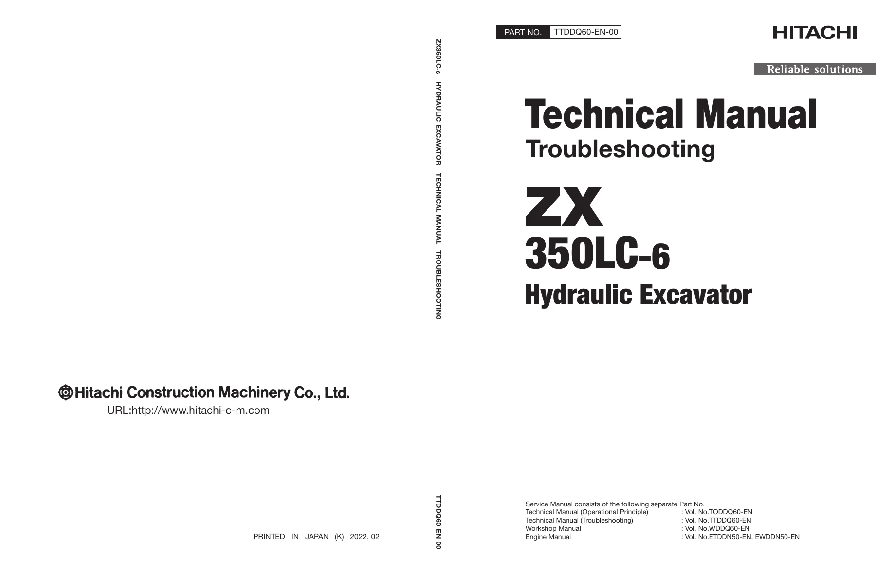
Hitachi ZX350LC-6 Excavator Technical Troubleshooting Manual – TTDDQ60-EN-00 PDF β€” PDF page 1 preview
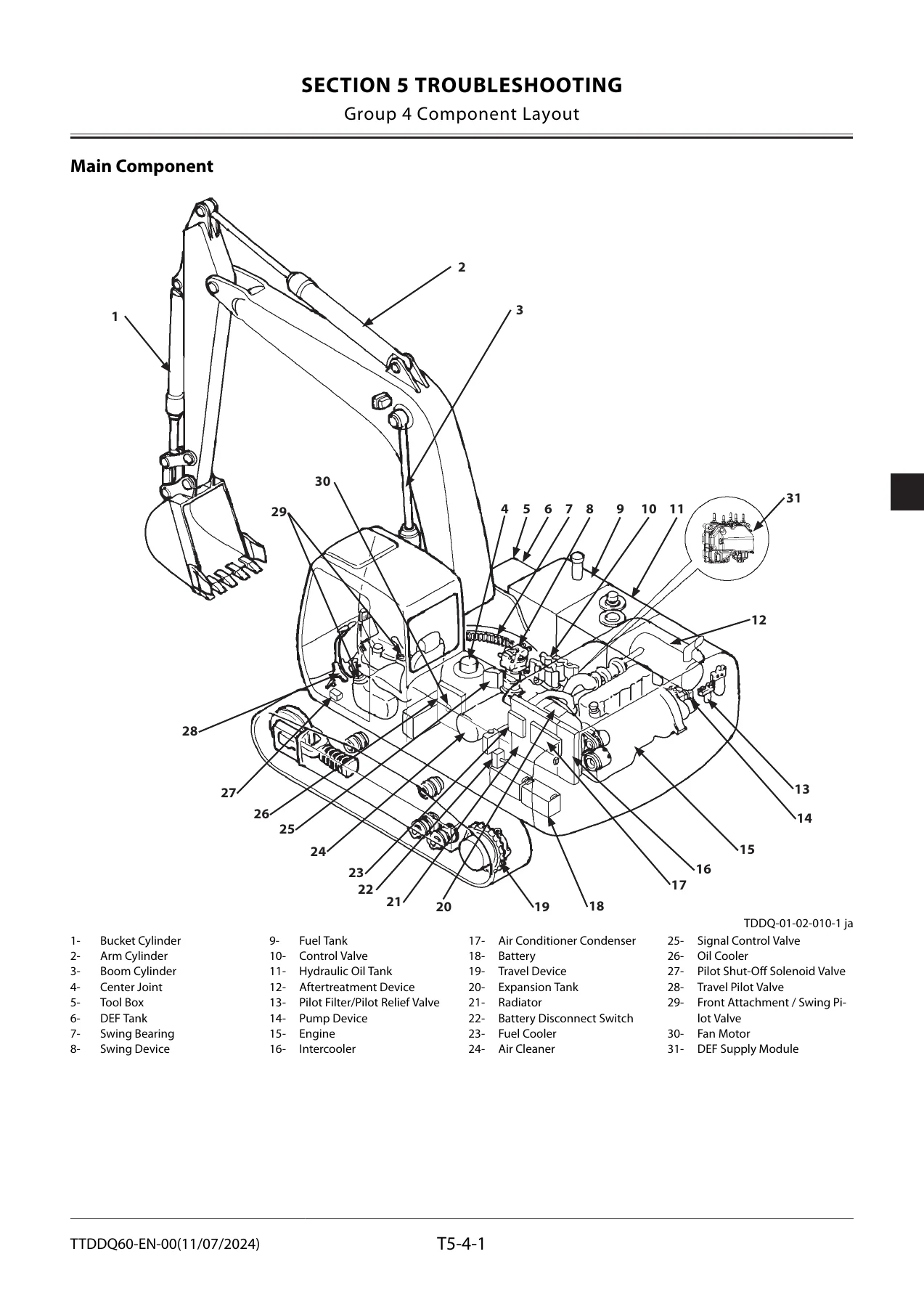
Hitachi ZX350LC-6 Excavator Technical Troubleshooting Manual – TTDDQ60-EN-00 PDF β€” PDF page 275 preview
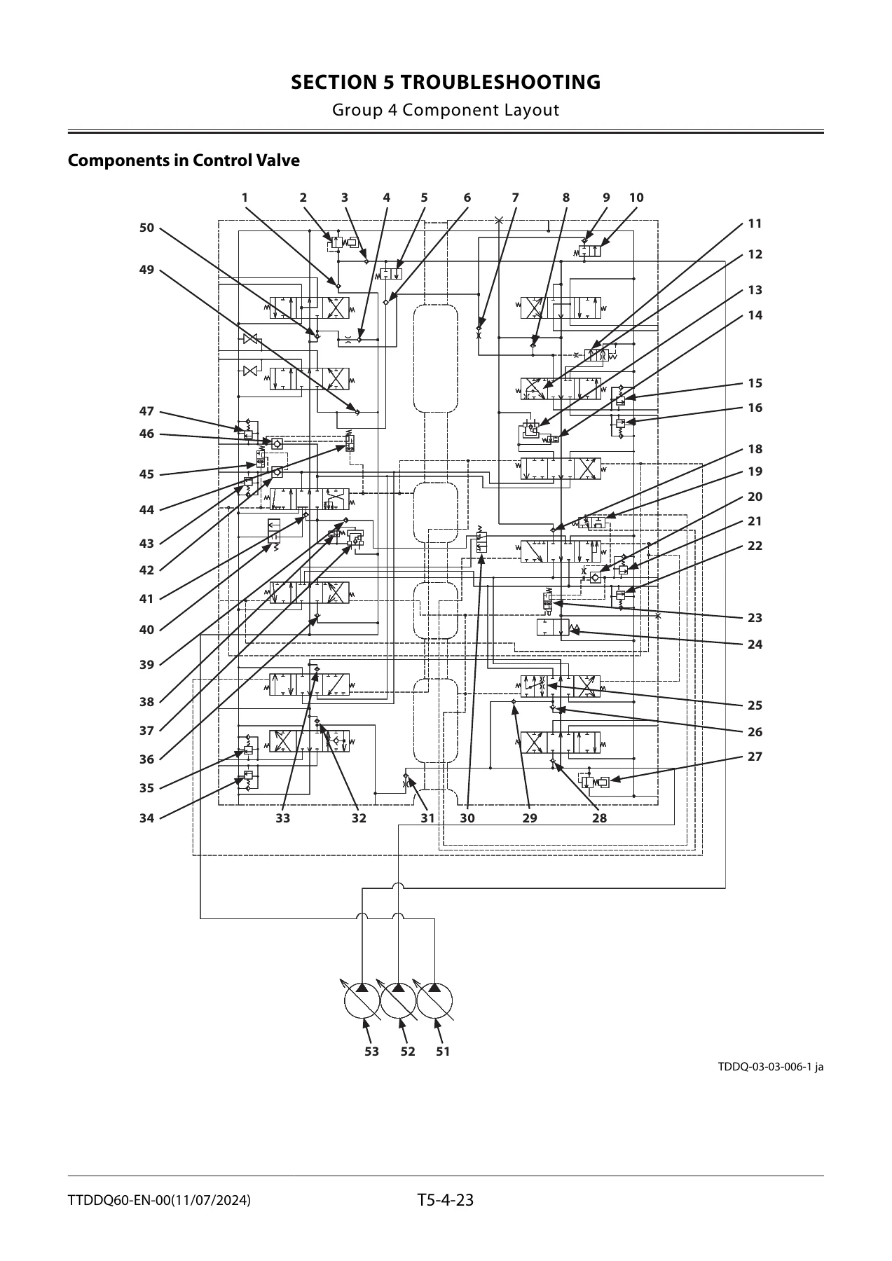
Hitachi ZX350LC-6 Excavator Technical Troubleshooting Manual – TTDDQ60-EN-00 PDF β€” PDF page 297 preview

This Hitachi ZX350LC-6 Excavator Technical Troubleshooting Manual is delivered as an instant PDF download after payment. No waiting for shipping, no physical media. You can access it on any device – laptop, tablet, or smartphone – and print the pages you need for the workshop. The PDF format lets you search for fault codes, specifications, or procedures quickly, so you spend less time flipping through pages and more time diagnosing and repairing the machine.
Reviews

There are no reviews yet.

Be the first to review “Hitachi ZX350LC-6 Excavator Technical Troubleshooting Manual – TTDDQ60-EN-00 PDF”

What Our Customers Say

β˜…β˜…β˜…β˜…β˜… Live reviews from customers
Loading customer reviews...
0
    0
    Your Cart
    Your cart is emptyReturn to Shop
    πŸ›’
    Recently Purchased
    πŸ•’ verified order