
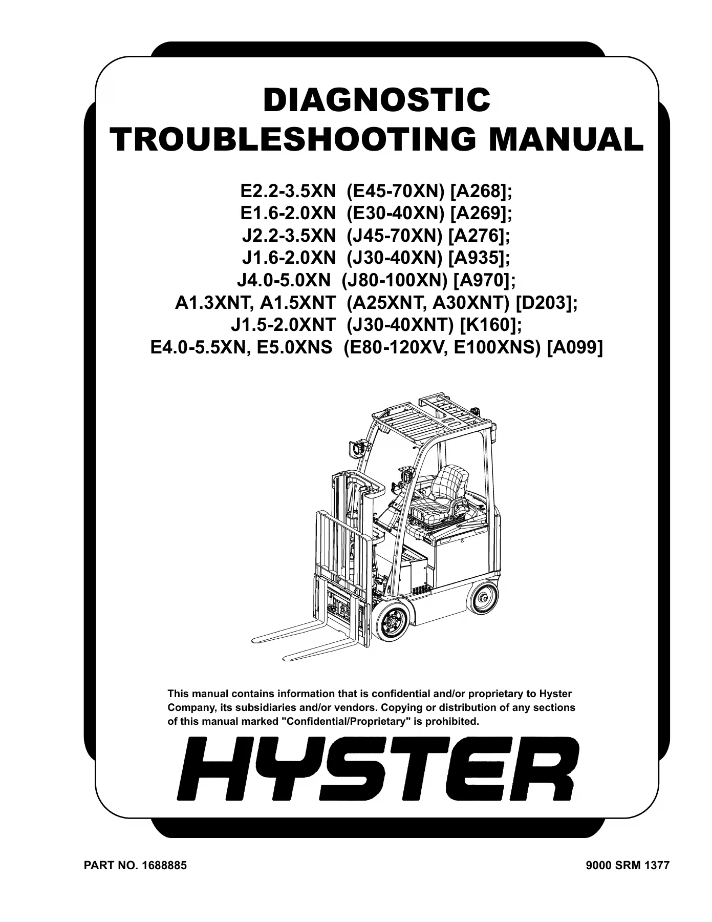
Hyster XN XNT Electric Forklift Diagnostic Troubleshooting Manual 1688885 – E2.2-3.5XN, E1.6-2.0XN, J2.2-3.5XN, J1.6-2.0XN, J4.0-5.0XN, A1.3XNT, A1.5XNT, J1.5-2.0XNT, E4.0-5.5XN, E5.0XNS
Original price was: $79.95.$49.95Current price is: $49.95.
Complete Hyster XN & XNT electric forklift diagnostic troubleshooting manual, document 1688885. Covers all DTCs, electrical, hydraulic, drive axle, mast and chassis systems across E2.2-3.5XN through E5.0XNS models. 1089-page PDF.
Description
When a Hyster electric forklift throws a fault code or loses traction mid-shift, guessing is not an option. This Hyster XN XNT Electric Forklift Diagnostic Troubleshooting Manual (document number 1688885) is the complete diagnostic guide for the XN and XNT series, covering models E2.2-3.5XN, E1.6-2.0XN, J2.2-3.5XN, J1.6-2.0XN, J4.0-5.0XN, A1.3XNT, A1.5XNT, J1.5-2.0XNT, E4.0-5.5XN, and E5.0XNS. It gives technicians the same systematic troubleshooting procedures, DTC charts, and system diagnostics used to keep these electric trucks running.
File Details
- Manual Type: Diagnostic Troubleshooting Manual
- Brand: Hyster
- Model Series: XN & XNT Electric Forklifts
- Models Covered: E2.2-3.5XN (E45-70XN), E1.6-2.0XN (E30-40XN), J2.2-3.5XN (J45-70XN), J1.6-2.0XN (J30-40XN), J4.0-5.0XN (J80-100XN), A1.3XNT, A1.5XNT (A25XNT, A30XNT), J1.5-2.0XNT (J30-40XNT), E4.0-5.5XN, E5.0XNS (E80-120XV, E100XNS)
- Language: English
- Page Count: 1089
- File Format: PDF
- Document Number: 1688885
Chapters Covered
- 9010 – Operational Diagnostic Procedures
- 9025 – Traction Motor
- 9030 – Electrical System
- 9035 – Drive Axle/Unit
- 9050 – Hydraulic Systems
- 9060 – Operators Station
- 9070 – Front End (Mast) and Chassis
- 9080 – Supplementary Data
9010 – Operational Diagnostic Procedures
This section provides a complete operational checkout that can be performed from the operator’s seat. It begins with key icon and wrench icon diagnostics, display panel checks, and battery settings, then moves through operator presence system verification, display backlight and icon power checks, light circuit, horn circuit, backup alarm, heater, brake pedal, park brake sensor, park brake, brake and axle drag, priority flow divider valve, mast cushion checks for both free lift and main lift cylinders, lift drift, lift/tilt mast adjustment, tilt function drift, tilt racking, tilt lock piston, chain and header hose adjustment, chain sheave, carriage adjustment for standard and integral sideshift configurations, and steering relief valve low pressure checks. Each check is presented in a structured format with the procedure and the action required based on the result, so you can follow the sequence and confirm repairs before moving on.
9025 – Traction Motor
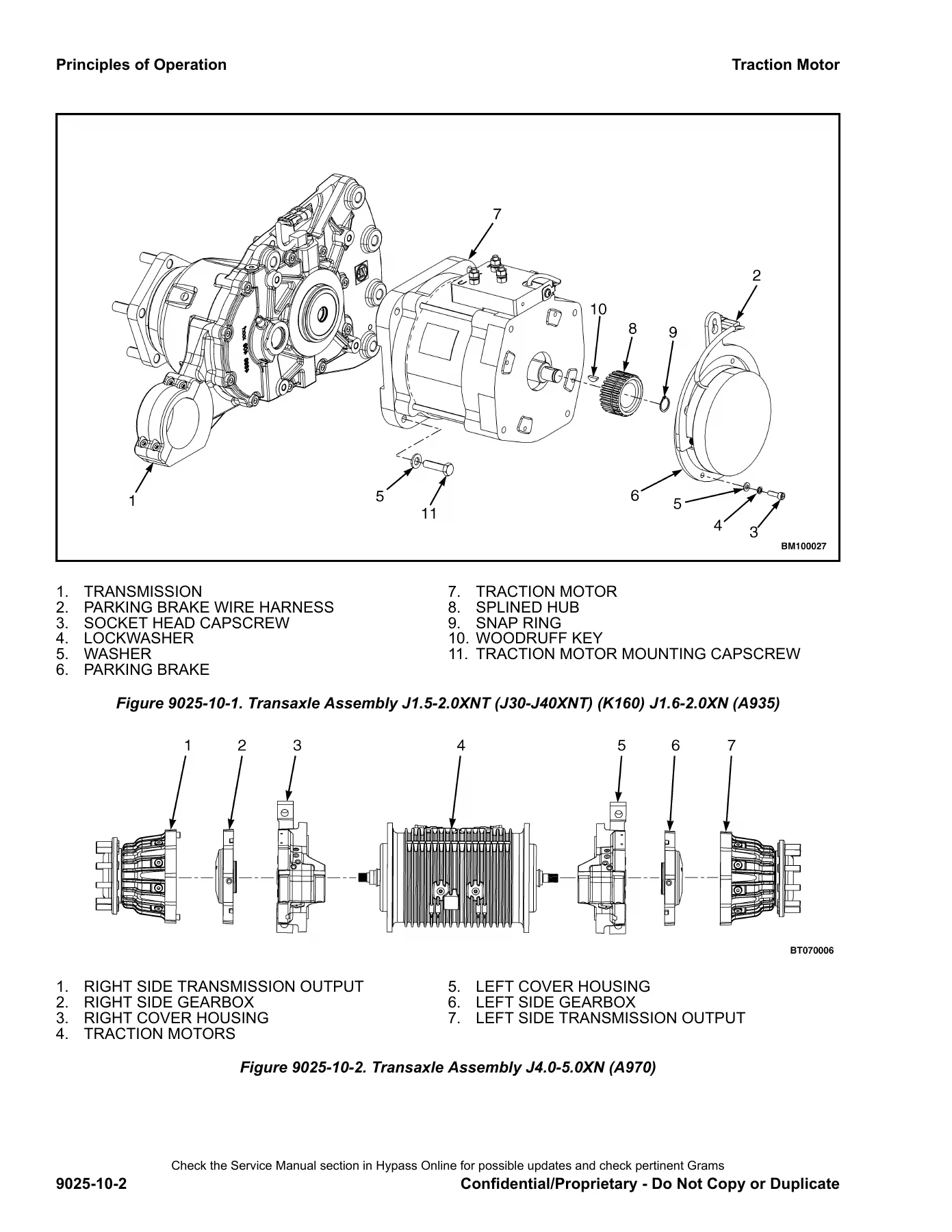
The traction motor section explains how the three-phase AC induction motors work across the product line, including how the traction motor controller converts DC battery power to AC and manages speed, direction, and regenerative braking through the Vehicle System Manager (VSM). It covers the speed sensor and temperature sensor functions, the master drive unit (MDU) for the D203 model, and the two-motor configurations used on K160, A935, A276, and A970 models. Transaxle assembly illustrations show the transmission, parking brake, traction motor, splined hub, snap ring, woodruff key, and mounting hardware. The observed symptoms section addresses poor tractive performance with causes that include incorrect speed limit settings, speed limiting enabled, failed checklist items, incorrect steer position sensor calibration, incorrect motor controller settings in the configuration data file (CDF), E-Boost active, motor phase shorted to frame, and incorrect motor installed.
9030 – Electrical System
This is the largest and most detailed section of the manual, covering the complete electrical system and its diagnostic procedures. It starts with general maintenance and diagnostic data, including troubleshooting guidelines that explain how to use the manual, how to read the DTC chart, safety precautions for working on electric lift trucks, and the proper use of a digital multimeter. The wiring reference data explains the circuit function identification system, wire color codes, and connector identification. Harness assembly data provides detailed illustrations and connector identifications for the auxiliary key switch, steering, display, main electro-hydraulic, main manual-hydraulic, front switch, backup alarm, lights, manual hydraulics, turn signal, synchro steer, park brake, steering column, seat, and main harness assemblies.
The principles of operation chapter covers the battery, contactor, fuses, relays, wire harnesses, DC/DC converter, operator interface, display panel, controllers, motor controllers, E-Hydraulics mini levers module (MLM), CANbus communication, system controlled outputs, valve coils, lights, backup alarm, cab options, and power distribution. The diagnostic trouble codes chapter is the heart of the manual, providing detailed troubleshooting procedures for hundreds of DTCs covering load weigh and service brake pressure sensors, accelerator pedal position sensors, steering wheel and steering axle position sensors, hydraulic temperature and fluid level sensors, park brake and mast tilt position sensors, travel direction select sensors, seat sensor, battery voltage, VSM 5-volt supply, manual hydraulic position sensors, E-hydraulic enable system data, E-hydraulic coil faults, CAN communication failures for both CBB 4-wheel and DBB 4-wheel configurations, MLM failures, VSM 12-volt supply, display internal failures, keyswitch relay output failures, VSM controller checks, controller logic failures, display temperature and buzzer failures, contactor/relay/valve coil faults, motor controller contactor failures, motor controller capacitor failures, motor speed sensor failures, motor auto brake failures, motor controller power MOSFET failures, motor/motor controller failures, motor controller CAN communication failures, travel direction select incorrect, direction select data incorrect, motor/motor controller temperature sensor failures, motor controller current sensor failures, hydraulic calibration required, motor controller 15-5 volt internal failures, motor controller DC bus low/high, traction controller driver current high, synchronous steering coil current, electric steer loss of communication, electric steer EEPROM checksum failure, key switch voltage, motor phase voltage measurement faults, controller temperature above limit, electric steer motor temperature above limit, controller internal errors, electric steer default parameter restore, rapid change in steering wheel position, steer wheel sensor output mismatch, steering wheel position error, TFD current and resistance faults, TFD short to battery negative, TFD stand-by current, steering motor locked, steer axle slow response, steer axle position mismatch, steer axle sensor output mismatch, rapid change in steer axle position, primary and secondary parameter mismatch, loss of CAN communication, internal software errors, 5V internal supply out of range, sensor ground current, motor temperature sensor open and short circuit, motor temperature OORH, fan driver current, internal hardware errors, sensor supply reference voltage, automatic park brake driver current, speed sensor high current and not connected, sensor supply circuit out of range, loss of speed sensor channel B, encoder errors, wrong encoder set, battery low, check up needed, forward + back, wrong slave version, controller mismatch, parameter transfer, no slave enabled, initial VMN high, standby current high, VMN low and high, waiting for node, brake pedal sensor faults, FOC configuration mismatch, various CAN errors, watchdog, FOC2 traction controller EEPROM checksum failure, power transistor shorted, output mismatch, coil short hardware KO, motor U-V phase voltage measurement fault, initial and operating nominal motor voltage faults, standby current too high, DC bus capacitor charge timeout, motor temperature above limit, EEPROM KO, wrong RAM memory, waiting for slave node response, hardware fault, motor temperature sensor KO, waiting for node, no CAN message, current gain, contactor coil shorted, contactor open and closed, contactor driver shorted high and low, analog input, IQ mismatch, data acquisition, thermic sensor KO, field oriented control KO, rotor stall, Vkey off shorted, DC bus high and key voltage low, watchdog slave, DC bus high/key voltage low, standby current too high, thermal protection, encoder error, EEPROM KO slave, wrong RAM memory slave, waiting master, W.D. SYNCRO, coil short hardware KO, analog input, controller mismatch, SP mismatch, aux drive open, aux driver short, no CAN message, controller internal temperature OORL and OORH, thermal protection/motor temperature high, and motor temperature high. The observed symptoms chapter covers no display/no truck operation, motor controller fan failure, motor/motor controller temperature sensor failure, horn failure, and lights inoperative. The icons and graphics chapter provides a glossary of the icons used throughout the diagnostic procedures.
9035 – Drive Axle/Unit
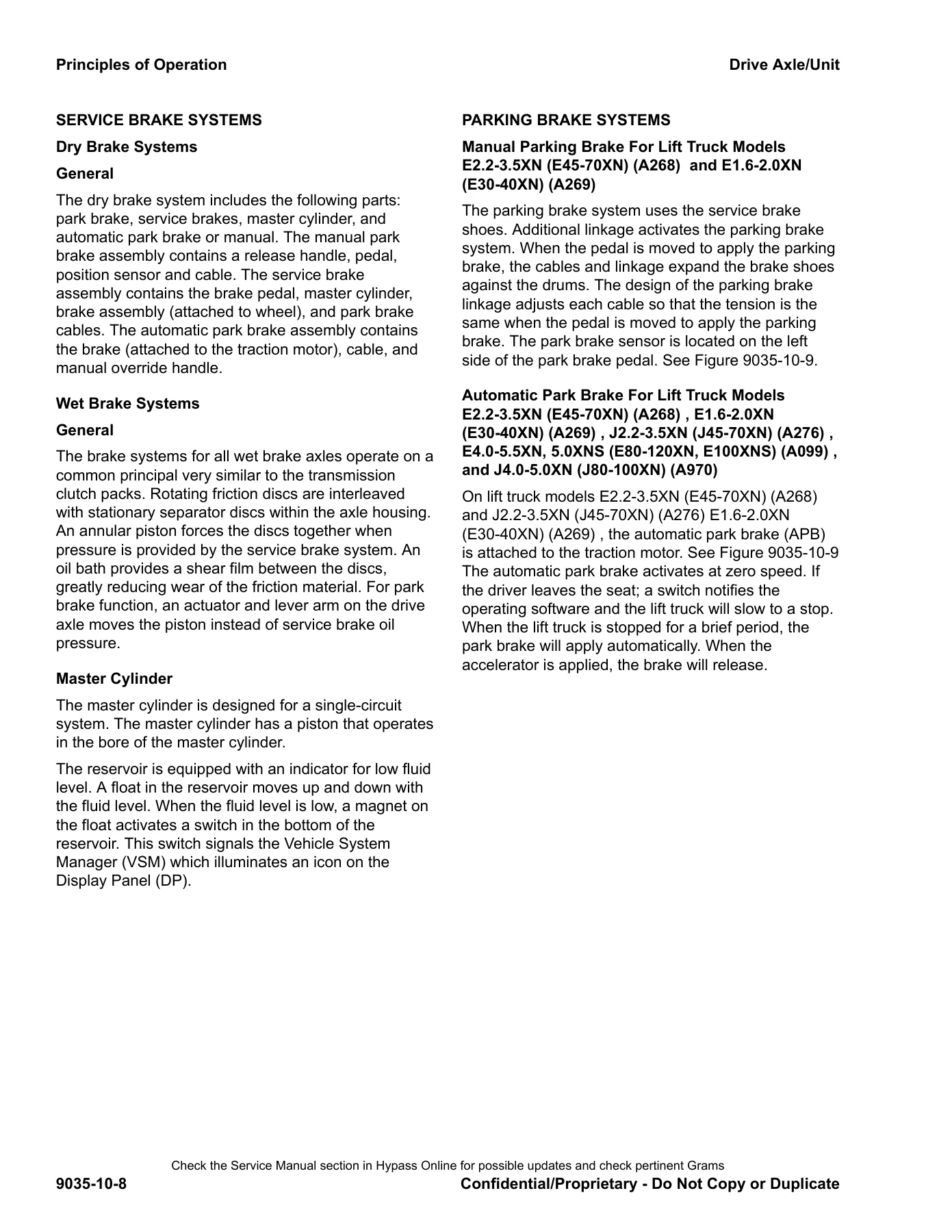
The drive axle and drive unit section covers the principles of operation for the transaxle used on J1.5-2.0XNT and J1.6-2.0XN models, the conventional drive axle used on E2.2-3.5XN, E1.6-2.0XN, E4.0-5.5XN, E5.0XNS, and J4.0-5.0XN models, and the transaxle used on J2.2-3.5XN and J4.0-5.0XN models. It describes the dual in-line drive units, wet disk service brakes, master cylinder with fluid level sensor, spring-applied electrically released park brake, manual and automatic parking brake systems, and the MONOTROL pedal. The observed symptoms chapter covers one drive wheel not moving, noise during operation that is not normal, oil leaks, park brake does not operate properly, and motion inhibited. A comprehensive park brake troubleshooting guide addresses slow park brake release, slow park brake apply, no park brake apply, partial park brake apply, no park brake release, partial park brake release, unintentional park brake apply, park brake noise, judder/vibration, no manual override, park brake engagement frequency too high or too low, with possible solutions and actions for each.
9050 – Hydraulic Systems
The hydraulic systems section covers manual hydraulic main control valves in both open center and closed center configurations, E-hydraulic main control valves, and the steering system. It explains the construction and operation of inlet assemblies, priority steer, relief cartridges, unloading spools, lift sections, tilt sections, auxiliary and dual auxiliary sections, hydraulic oil coolers, outlet cover sections, pilot cartridges, electro-hydraulic solenoids, spacer sections, and steering control units. The observed symptoms chapter for gear pump issues covers abnormal hydraulic noise and/or vibration, abnormal smell/discoloration/foaming of oil, cycle times too fast, jump/delay in lift or lower activation, jump/delay in auxiliary function actuation, jump/delay in tilt forward or back actuation, forks drop slightly before lifting, forks lower without command, forks raise or actuate without command, hydraulic oil cooler not functioning correctly, intermittent activation while commanding function, forks tilt forward without command, lift/lower function maximum speed too slow, lift function will not move with MLM movement, lift/lower continues to move after MLM is released, lift/lower/auxiliary function suddenly jumps in middle of stroke, lower function will not move with MLM movement, poor metering on lift or lower functions, auxiliary function continues to move after MLM is released, auxiliary function maximum speed too slow, auxiliary function or tilt back moves without command, auxiliary function/tilt back/tilt forward will not move with MLM movement, tilt forward or tilt back function continues to move when MLM is released, tilt forward or tilt back will not move with MLM movement, too much MLM movement (deadband) to start function moving, wrong actuation operates or actuation is backward, actuation exhibits slight movement in opposite direction before moving, auxiliary function is slow or does not function, cycle times too fast for manual valve, function continues to activate after returning to neutral, lift function is slow or does not function, tilt back function will not operate, tilt forward or tilt back will not function when activated, no steering, steering is slow or difficult, steering operation is not smooth, steering wheel end lock position cannot be felt by operator, steering wheel turns by itself or does not return to neutral, steering wheel turns the tires in the wrong direction, actuations do not act simultaneously, oil leaking/component life too short, abnormal steer axle noise, abnormal steering wheel vibration, and back lash/kick back in steering wheel. The tests and adjustments chapter covers hydraulic warm-up, primary and secondary relief valve tests, hydraulic pump flow test, main control valve LS leakage test, unloader margin test, E-hydraulic valve leakage test, steering relief pressure test, steering control unit LS pressure test, lift cylinder leakage test, tilt cylinder leakage test, and steering cylinder leakage test.
9060 – Operators Station
The operators station section covers the general description and location of operator station components, the display panel with its LCD screen, warning and indicator lights, and numerical keypad, the programming menus including the operator cycle main menu and supervisor/service cycle main menu, the display menu flowchart, manual hydraulic control levers for lift/lower, tilt, auxiliary 1, and auxiliary 2, the emergency disconnect switch, the E-hydraulic system interface with mini lever module, return-to-set-tilt (RTST), and emergency disconnect switch, lighting control for front work lights, front marker lights, front/rear turn signal lights, rear tail lights, rear work light, rear backup lights, rear stop lights, strobe light, and dome light, and cab panels including covers and floor plates, hood and seat, cab heating system, and wiper/washer system.
9070 – Front End (Mast) and Chassis
The front end and chassis section covers the principles of operation for the mast, carriages, integral sideshift carriage, mast mounts, two-stage full free-lift mast, two-stage limited free-lift mast, three-stage full free-lift mast, four-stage full free-lift mast, cylinder cushion during lifting and lowering sequences, tilt and sideshift cylinders, lowering control valves, and chassis components including the overhead guard and counterweight. The observed symptoms chapter covers abnormal channel wear, abnormal hose wear, abnormal mast noise, body panels making noise, external leakage from free-lift or main lift cylinders, FFL mast banging during phasing, high tire wear on drive axle and steer axle, hoses not tracking correctly, integral sideshift moving too fast or not moving/slow, fork positioner not moving or slow, mast is loose, mast lift chains are loose, mast or carriage binding, mast/carriage bounces or is spongy, misphasing of full free-lift mast, overhead guard loose or damaged, racking during lift, racking during tilt, truck feels unstable, truck wanders/does not track straight or steer well, and wheel studs breaking.
9080 – Supplementary Data
The supplementary data section provides a comprehensive table of abbreviations and acronyms used throughout the manual, covering terms from AC and ACC to USB and including definitions for CANbus, CDF, CPS, CRP, DCS, DTC, EEPROM, E-HPV, FFL, LFL, MLM, MDU, OORH, OORL, PPRV, PTC, RTST, SCU, SRM, STB, STG, and many more.
Why This Manual Matters
When a Hyster XN or XNT electric forklift throws a diagnostic trouble code, the difference between a quick fix and a long downtime is having the right troubleshooting procedure. This manual doesn’t just list fault codes; it walks you through the diagnostic process step by step, showing you what to measure, where to measure it, what values to expect, and what to do based on what you find. The electrical system section alone contains hundreds of DTC-specific procedures with schematics showing connector pinouts, wire colors, circuit numbers, and component locations. The hydraulic section includes complete test procedures for relief valves, pump flow, cylinder leakage, and steering systems, with specifications and adjustment procedures. The drive axle and mast sections cover the mechanical systems with observed symptoms and step-by-step causes and corrections.
Whether you’re a fleet maintenance technician keeping a warehouse running, a shop owner servicing customer trucks, or an operator who wants to understand what’s happening under the hood, this manual gives you the information you need. The operational checkout procedures in section 9010 are designed so you can quickly verify the machine’s condition from the operator’s seat before diving into deeper diagnostics. The DTC chart and fault log procedures let you retrieve stored fault history and identify intermittent problems. The system-by-system organization makes it easy to find what you need, whether you’re chasing an electrical gremlin, a hydraulic leak, or a mast that won’t lift straight.
IMAGES PREVIEW
Instant PDF Delivery
This manual is delivered as an instant PDF download after payment. No waiting for shipping, no physical media to lose or damage. Open it on any device — laptop, tablet, or smartphone — and print whatever pages you need for the shop floor. The PDF format means you can zoom in on detailed illustrations, search for specific DTC numbers or component names, and keep the entire 1089-page manual organized on your computer or in the cloud. Whether you’re doing a quick diagnostic check or a complete system overhaul, the information is at your fingertips.
Reviews
There are no reviews yet.