
Hyundai HX330S L Crawler Excavator Shop Service Manual
Original price was: $39.95.$22.95Current price is: $22.95.
Workshop shop manual for the Hyundai HX330S L crawler excavator covering structure, hydraulics, electrics, CAPO mechatronics, troubleshooting, performance tests, and component overhaul with the Hyundai HM8.3 engine.
Description
Hyundai HX330S L Crawler Excavator Shop Service Manual
This Hyundai HX330S L Crawler Excavator Shop Service Manual is the workshop reference used to understand, diagnose, and rebuild the HX330S L long-undercarriage machine. It is written for service-shop work: how each major assembly is built, how oil and pilot pressure move through the circuits, how the ADVANCED CAPO controller manages engine and pump power, and how to take a component apart and put it back together without guessing at torque, sequence, or test limits.
File Details
- Manual type: Shop / service workshop manual
- Brand / model: Hyundai HX330S L crawler excavator
- Language: English
- Page count: 563
- File format: PDF
Machine Coverage in This Manual
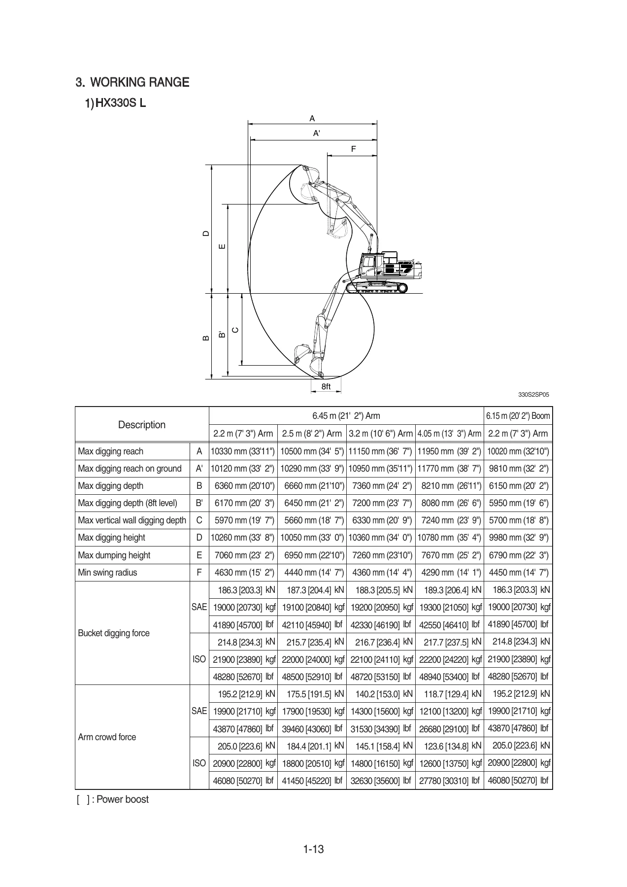
The specifications and working-range tables are written around the HX330S L. Standard configuration shown for the 6.45 m (21′ 2″) boom and 3.20 m (10′ 6″) arm lists an operating weight of 33000 kg (72750 lb) with the 600 mm shoe, a 1.44 m³ (1.88 yd³) SAE heaped bucket, travel speeds of 3.6 / 6.4 km/hr, swing speed of 11.2 rpm, gradeability of 35 degrees (70%), ground pressure of 0.64 kgf/cm² (9.03 psi), and maximum traction force of 29500 kg (65030 lb). A second specification set is given for the 6.15 m (20′ 2″) boom and 2.2 m (7′ 3″) arm at 32806 kg (72325 lb).
Working-range data covers boom and arm combinations of 6.45 m with 2.2 m, 2.5 m, 3.2 m, and 4.05 m arms, plus the 6.15 m boom with the 2.2 m arm. Bucket digging force and arm crowd force are listed to both SAE and ISO methods, with power-boost values in brackets. Lifting-capacity charts follow SAE J1097 and ISO 10567 for those same boom-arm pairings with the 6000 kg counterweight and 600 mm shoe. Bucket selection tables cover general, heavy-duty, and rock-heavy-duty buckets from 1.44 m³ through 2.10 m³ SAE heaped, with density limits for each boom-arm pairing.
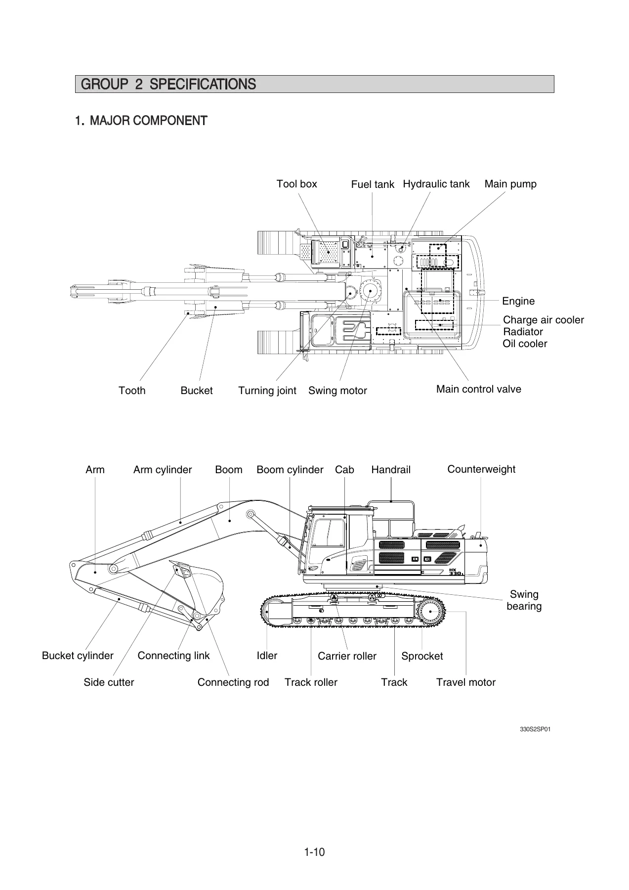
Undercarriage data describes an X-leg center frame with dry tracks, lubricated rollers, hydraulic track adjusters, and triple-grouser shoes in 600 mm (standard), 700 mm, and 800 mm widths. Each side uses 2 carrier rollers, 9 track rollers, and 48 shoes. Assembly-weight tables break the machine into upperstructure, main frame, engine, main pump, main control valve, swing motor, tanks, 6000 kg counterweight, cab, radiator, oil cooler, lower chassis, swing bearing, travel motors, turning joint, idlers, sprockets, rollers, track-chain, and front attachment pieces including the 6.45 m boom, 3.2 m arm, 1.44 m³ bucket, and the three work-equipment cylinders.
Engine and Major Component Data
The engine table names the Hyundai HM8.3: a 4-cycle turbocharged charge-air-cooled diesel, water cooled, 6 cylinders in-line, firing order 1-5-3-6-2-4, direct injection. Bore and stroke are 114 × 134.9 mm, displacement 8290 cc (506 cu in), compression ratio 18:1. Rated net power is 245 Hp (183 kW) at 2200 rpm (SAE J1349); rated gross power is 250 Hp (186 kW) at 2200 rpm (SAE J1995). Maximum torque is 124 kgf·m (899 lbf·ft) at 1300 rpm. Engine oil quantity is 26.5 ℓ (7.0 U.S. gal). High idle is 2457+50 rpm and low idle is 850±100 rpm. Starting motor is 24V-7.2 kW, alternator 24V 90A, batteries 2 × 12V × 150Ah.
IMAGES PREVIEW
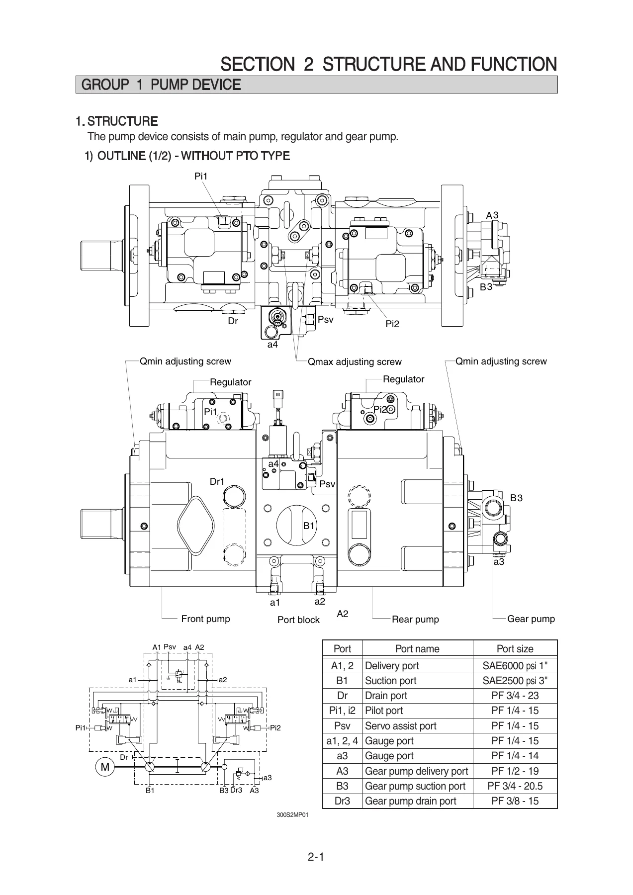
The main pump is a variable-displacement tandem axial piston unit, 2 × 175 cc/rev, rated oil flow 2 × 306 ℓ/min at 1750 rpm. The gear (pilot) pump is a fixed-displacement single-stage unit at 15 cc/rev, 40 kgf/cm² (570 psi), 26.3 ℓ/min. The 10-spool main control valve is pilot operated, with main relief at 350 kgf/cm² (4980 psi) and 380 kgf/cm² (5400 psi) under power boost, and overload relief at 400 kgf/cm² (5690 psi). The swing motor is an axial-piston unit at 156.9 cc/rev with 300 kgf/cm² relief, spring-applied hydraulic-released brake, 84.4 kgf·m braking torque, and a 2-stage planetary reduction. Travel motors are variable-displacement axial-piston units, 282.6 / 156.9 cc/rev, 350 kgf/cm² relief, 134 kgf·m braking torque. Cylinder sizes are boom Ø150 × Ø105 × 1480 mm, arm Ø160 × Ø110 × 1685 mm, and bucket Ø140 × Ø100 × 1285 mm.
Recommended-oil charts give capacities and viscosity by ambient temperature: engine oil pan 26.5 ℓ, swing drive 11 ℓ, final drives 7.8 ℓ × 2, hydraulic tank 210 ℓ / system 414 ℓ, fuel tank 600 ℓ, radiator mixture 27 ℓ. Filter-interval notes on the cluster list engine oil and engine-oil filter at 500 hours, fuel filter at 500 hours, and several gear and hydraulic filters at 1000 hours.
Chapters Covered
- Section 1 General — Safety hints; Specifications (major components, dimensions, working range, weights, lifting capacities, bucket selection, undercarriage, major-component specs, recommended oils)
- Section 2 Structure and Function — Pump device; Main control valve; Swing device; Travel device; RCV lever; RCV pedal
- Section 3 Hydraulic System — Hydraulic circuit; Main circuit; Pilot circuit; Single operation; Combined operation
- Section 4 Electrical System — Component location; Electric circuit; Electrical component specification; Connectors
- Section 5 Mechatronics System — Outline; Mode selection; Automatic deceleration; Power boost; Travel speed control; Automatic warming up; Engine overheat prevention; Variable power control; Attachment flow control; Intelligent power control; Anti-restart; Self-diagnostic system; Engine control system; EPPR valve; Monitoring system; Fuel warmer system
- Section 6 Troubleshooting — Before troubleshooting; Hydraulic and mechanical system; Electrical system; Mechatronics system
- Section 7 Maintenance Standard — Operational performance test; Major components; Track and work equipment
- Section 8 Disassembly and Assembly — Precaution; Tightening torque; Pump device; Main control valve; Swing device; Travel device; RCV lever; Turning joint; Boom, arm and bucket cylinder; Undercarriage; Work equipment
Taken as a whole, the Hyundai HX330S L Crawler Excavator Shop Service Manual gives a technician the map from first safety lockout through component theory, circuit tracing, cluster diagnostics, measured performance limits, and bench-level rebuild of the pump, valve, swing and travel drives, remote controls, turning joint, cylinders, undercarriage, and front attachment.
Hydraulics, Structure, and Circuit Logic
Section 2 opens the pump device as a front-and-rear piston pump with regulators and a gear pump, shown both without and with PTO. Cutaways name the rotary group, swash-plate group, and valve-block group and explain negative-flow control, total horsepower control, and power-shift control. Main-control-valve pages walk each spool path. Swing and travel chapters cover parking-brake, relief, makeup, and high/low speed changeover hardware. RCV lever and pedal chapters show porting and single versus simultaneous operation.
Section 3 then traces oil in the machine. The hydraulic system uses one main pump, one control valve, one swing motor, four cylinders, and two travel motors. Suction, delivery, return, and drain circuits are drawn with bypass check-valve settings of 1.5 and 3.0 kgf/cm² on the cooler path and 1.5 kgf/cm² on the drain check. The pilot circuit feeds the remote-control valves, EPPR valves, solenoid packs, swing parking brake, and safety-lock solenoid from the 40 kgf/cm² pilot relief. Single-function pages cover boom, arm, bucket, swing, and travel. Combined-operation pages explain boom-up preference, arm-in flow limiting, confluence, regeneration, and simultaneous travel or swing work so a technician can see why one function steals oil from another.
Electrical System and Connectors
Cab and upperstructure location drawings identify the cluster, accel dial, starting switch, power-max and one-touch-decel switches, RS232 service socket, fuse and relay box, master switch, batteries, battery relay, alternator, MCU, pump EPPR and boom-priority EPPR valves, shuttle-block pressure sensors, air-cleaner sensor, and travel-alarm buzzer. Circuit groups cover start, charge, lighting, wiper, and related 24-volt paths with checkpoint voltages at STOP, START, and RUN. Connector tables list TE/AMP, Deutsch, and related housings, pin counts, and mating part numbers, including the Deutsch engine ECM connector and MCU connectors (one table notes a serial break at #0773 for a 40-pin MCU plug). Component-check notes include the engine-oil pressure switch at 0.5 kgf/cm² (N.C.) and governor-motor resistance checks.
ADVANCED CAPO Mechatronics
The controller suite is described as ADVANCED CAPO (Computer Aided Power Optimization). It matches engine and pump power for the selected work, watching engine speed, coolant temperature, hydraulic-oil temperature, and hydraulic pressure through the MCU, cluster, accel actuator, and EPPR valves. Power modes P, S, and E plus a 10-step accel dial and a memorized U-mode set engine rpm and EPPR power-shift pressure. Auto idle drops speed to 1200 rpm after four seconds of lever-neutral time and to 1000 rpm after one minute. Power boost raises main relief for a short, high-breakout interval. Travel speed control, automatic warm-up (coolant below 30°C raises speed to 1200 rpm), overheat logic above 100°C coolant or hydraulic oil, variable power versus RCV stroke, attachment flow control, intelligent power control, and anti-restart protection of the starter are each given their own group.
Self-diagnosis documents HCESPN plus FMI fault format, cluster error display, and checking lists for failed pressure displays, auto-idle faults, and engine/pump horsepower-control failures. Engine-control pages explain how the MCU varies EPPR output so pump absorption torque tracks engine torque. Monitoring coverage includes normal and premium clusters: rpm, coolant and hydraulic temperature, fuel, eco gauge, warning lamps (oil pressure, charging, air cleaner, overload, water-in-fuel), ESL password start, language and unit setup, and optional auto engine shutdown. Fuel-warmer operation is described for cold fuel, with cancel thresholds of about 60°C coolant and 45°C hydraulic oil.
Troubleshooting, Tests, and Rebuild Work
Before any chart is used, the book tells the technician to read the cluster monitor and logged fault codes. Hydraulic and mechanical trees cover pump-coupling noise, a running engine with no machine motion, unequal travel, weak or drifting boom/arm/bucket, and related mechanical causes. Electrical trees isolate coolant-overheat, air-cleaner, engine-oil-pressure, and hydraulic-temperature lamps, a no-start condition at the engine-stop solenoid, and charging faults. Mechatronics trees cover slow actuators with good engine speed (P 1950 ± 50, S 1850 ± 50, E 1750 rpm in one chart set; performance-test idle and mode speeds are also tabulated separately) and engine stall traced through EPPR current and pressure.
Section 7 is the pass/fail book for a machine that is back together. Tests include engine speed by mode, travel time over 20 m, three-revolution travel time, travel deviation, swing speed and drift, work-equipment cycle times (boom raise 4.0 ± 0.4 s, boom lower 3.1 ± 0.4 s, arm in regen on 3.3 ± 0.4 s), cylinder drift in mm/5 min, lever play and stroke, pilot and travel-speed pressures, swing-brake release (disengaged 40 kgf/cm², applied 0), and main and port relief settings for boom/arm/bucket, travel, and swing. Section 8 then gives removal and install order, air-bleed steps after pump or motor work, coating and seal-replacement notes, and tightening values such as engine-to-bracket M12 × 1.75 at 11.5 ± 1.0 kgf·m and bracket-to-frame M24 × 3.0 at 90 ± 9.0 kgf·m. Rebuild coverage runs through the pump device, main control valve, swing device, travel device, RCV lever, turning joint, boom/arm/bucket cylinders, undercarriage, and work equipment. Safety pages at the front cover lockout tagging, high-pressure injection injury, battery acid, cooling-system pressure, and support of a raised attachment.
Use This Manual on the Job
The Hyundai HX330S L Crawler Excavator Shop Service Manual supports pump and regulator overhaul, main-control-valve service, swing and travel motor and reduction-gear work, cylinder reseal, turning-joint service, track and roller work, boom/arm pin and linkage service, 24-volt circuit tracing, EPPR and MCU diagnosis, cluster fault-code work, relief and pilot-pressure setting, and operational performance testing after repair. Using the printed pressures, cycle times, drift limits, and torque figures keeps a 33-ton class excavator from being assembled to the wrong relief setting or returned to work with a weak cylinder or a mis-set power-shift pressure. Delivery is an instant PDF after payment: no shipping wait, readable on any device, and printable at the bench or in the field when the HX330S L is down.



Reviews
There are no reviews yet.