
Hyundai R140LC-9S R140LCD-9S R140LCM-9S Excavator Service Manual PDF
Original price was: $39.95.$24.95Current price is: $24.95.
566-page PDF service manual for Hyundai R140LC-9S, R140LCD-9S and R140LCM-9S excavators, covering hydraulic, electrical, mechatronics, troubleshooting, maintenance standards, disassembly and assembly, and mounting torque.
Description
Hyundai R140LC-9S Excavator Service Manual PDF
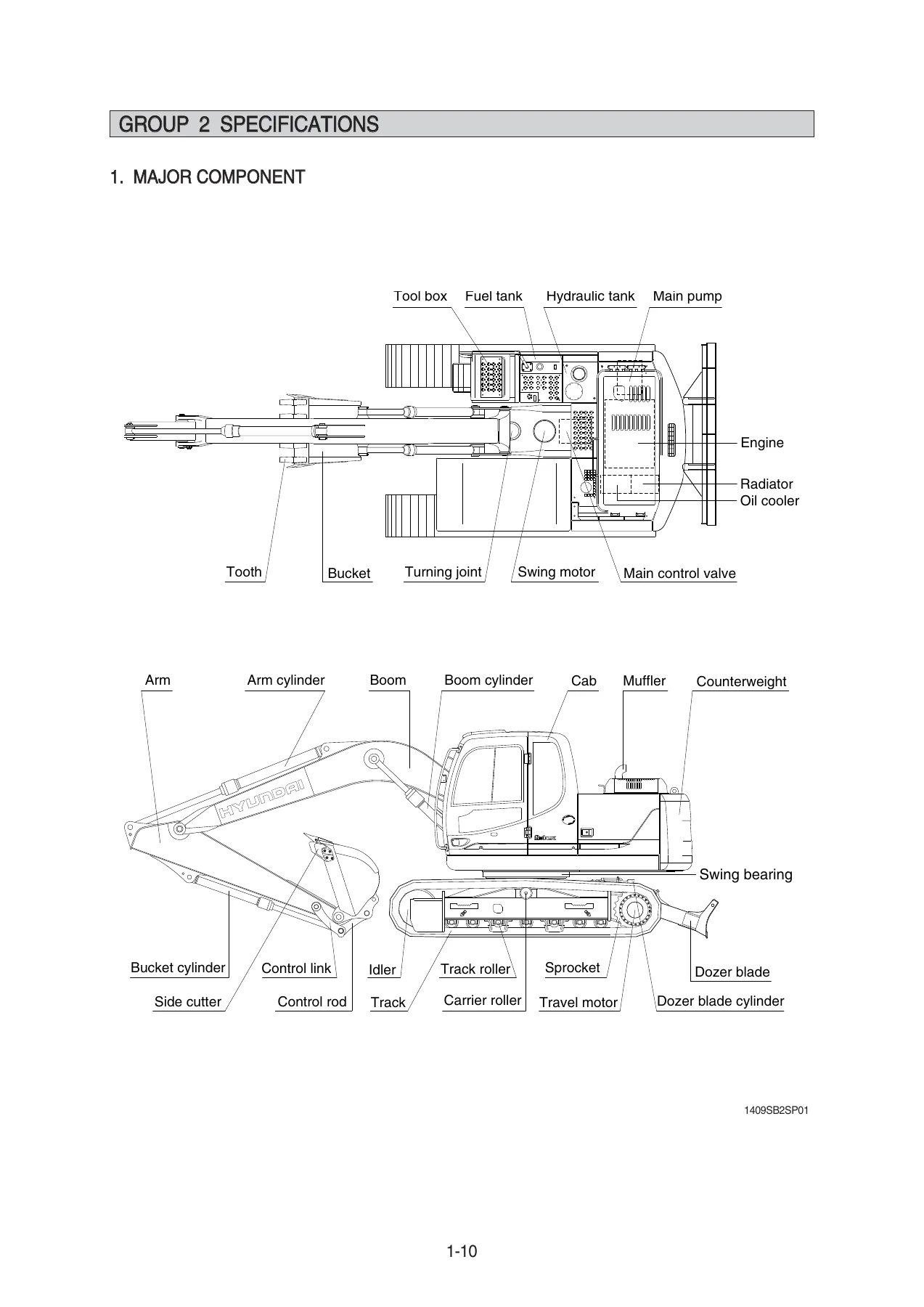
This 566-page service manual is a practical workshop reference for the Hyundai R140LC-9S, R140LCD-9S and R140LCM-9S excavators. It is arranged for technicians who need to understand how the machine systems work, trace a fault with a logical procedure, check wear against stated standards, and remove or rebuild major components with the correct tightening values. The document covers the R140LC-9S family across general specifications, structure and function, hydraulic and electrical systems, mechatronics, troubleshooting, maintenance standards, disassembly and assembly, and component mounting torque.
File Details
- Manual type: Service Manual
- Brand: Hyundai
- Models covered: R140LC-9S, R140LCD-9S, R140LCM-9S
- Engine covered: Cummins 6BT5.9
- Language: English
- Page count: 566
- File format: PDF
Chapters Covered
- Section 1 General — safety hints; specifications; working range; lifting capacities; bucket selection guide; undercarriage details; specifications for major components; recommended oils.
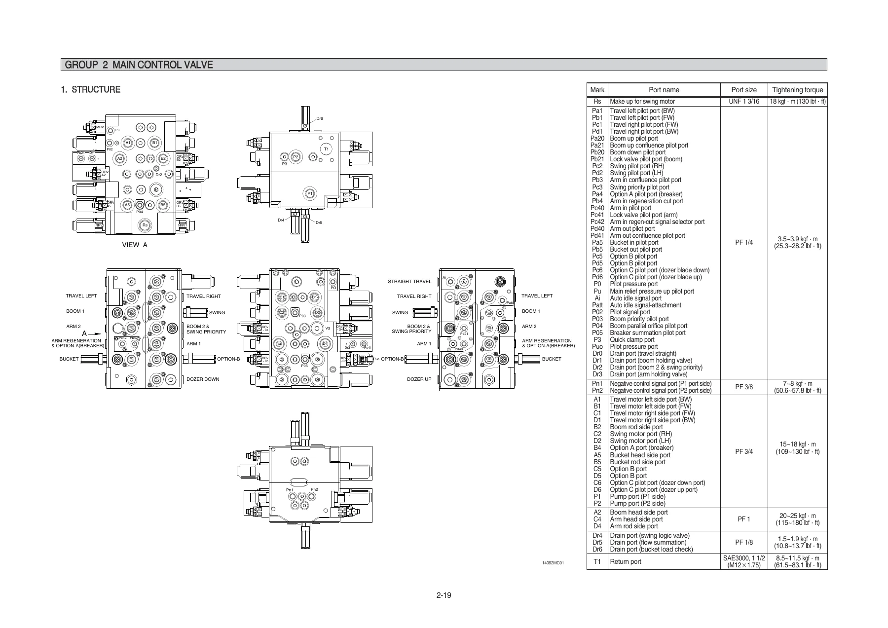
- Section 2 Structure and Function — pump device; main control valve; swing device; travel device; RCV lever; RCV pedal.
- Section 3 Hydraulic System — hydraulic circuit; main circuit; pilot circuit; single operation; combined operation.
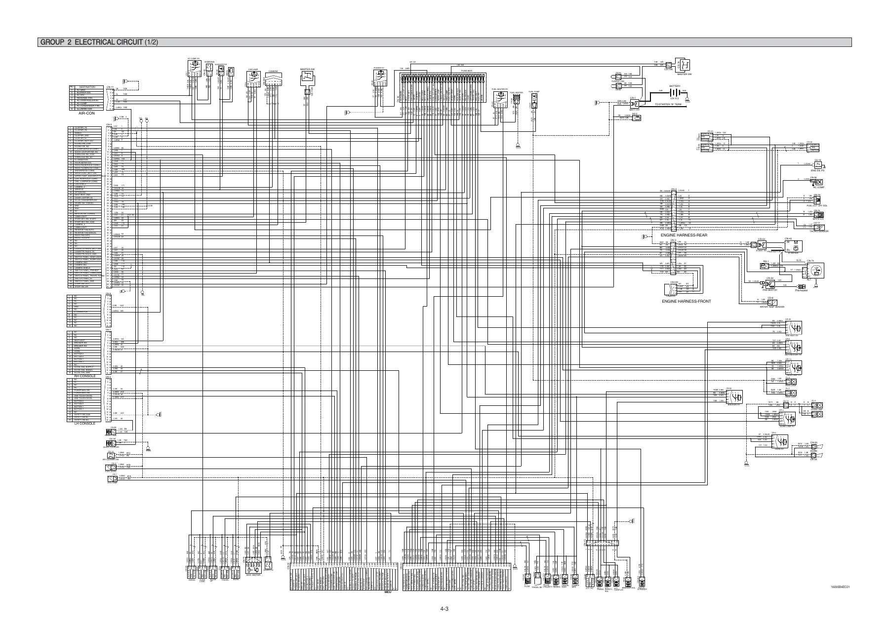
- Section 4 Electrical System — component location; electrical circuit; electrical component specification; connectors.
- Section 5 Mechatronics System — outline; mode selection system; automatic deceleration system; power boost system; travel speed control system; automatic warming up system; engine overheat prevention system; variable power control system; attachment flow control system; anti-restart system; self-diagnostic system; engine control system; EPPR valve; monitoring system; fuel warmer system.
- Section 6 Troubleshooting — before troubleshooting; hydraulic and mechanical system; electrical system; mechatronics system.
- Section 7 Maintenance Standard — operational performance test; major components; track and work equipment.
- Section 8 Disassembly and Assembly — precautions; tightening torque; pump device; main control valve; swing device; travel device; RCV lever; turning joint; boom, arm and bucket cylinder; undercarriage; work equipment.
- Section 9 Component Mounting Torque — introduction guide; engine system; electric system; hydraulic system; undercarriage; structure; work equipment.
For a technician working on an R140LC-9S, R140LCD-9S or R140LCM-9S, the value of this manual is in how the sections connect. The structure and function chapters explain what each major assembly does and how its internal parts interact. The hydraulic and electrical chapters give the circuit logic needed to follow oil or current through the machine. The mechatronics chapters explain how the MCU, cluster, EPPR valves, sensors and solenoids influence pump output, engine speed and work modes. The troubleshooting charts then turn that system knowledge into symptom-based checks, and the maintenance standards provide the measured limits needed to decide whether a part can remain in service. The disassembly and assembly chapters complete the chain by showing removal order, internal component relationships, seal replacement points and tightening torque values.
Engine, Pump and Hydraulic Service Reference
The manual identifies the engine as a Cummins 6BT5.9 four-cycle turbocharged diesel, six cylinders in line, 5880 cc displacement, rated 126 Hp at 2100 rpm, with a maximum torque of 53.6 kgf·m at 1500 rpm. It lists high idle at 2100±50 rpm and low idle at 800±100 rpm, along with starting, alternator, battery and fluid capacity information. These values support tune-up checks, performance testing and fault diagnosis where engine speed or power delivery is part of the complaint.
The main pump is described as a variable displacement tandem axis piston pump with two 65 cc/rev sections. The manual gives a maximum pressure of 350 kgf/cm2, rising to 380 kgf/cm2 in power boost, and rated oil flow of 2×123.5 L/min at 2000 rpm. The main control valve is an 11-spool hydraulic pilot unit with main relief, overload relief and negative control functions. The regulator section explains negative flow control, total horsepower control, power shift control and maximum/minimum flow adjustment. This is the material that lets a technician understand why pump output changes with pilot pressure, load pressure and power shift current rather than treating low flow or slow operation as a single fault.
Hydraulic system coverage includes the main circuit, pilot circuit, single-function operations and combined operations. Individual sections explain boom up and down, arm in and out, bucket in and out, swing, travel, dozer operation, holding valve action, arm regeneration, swing priority, straight travel, main relief valve operation and overload relief valve operation. These explanations are supported by circuit diagrams and port references, so a technician can follow the oil path for a specific function and compare it with the machine symptom.
Troubleshooting and Diagnostic Paths
The troubleshooting section is organized by system: hydraulic and mechanical, electrical, and mechatronics. It begins with a practical diagnostic sequence — study the system, question the operator, inspect the machine, confirm the complaint, perform the troubleshooting procedure, then trace the cause before repairing. The hydraulic and mechanical charts cover common complaints such as unusual pump noise, the engine starting but the machine not operating, cloudy hydraulic oil, abnormal oil temperature, cavitation, contaminated oil, swing faults, travel faults and attachment faults. The electrical section includes starting, charging, monitor display, communication error, warning lamp and solenoid checks. The mechatronics section addresses slow actuator speed, engine stall, cluster or mode selection faults, accel dial faults, auto decel faults, pressure sensor faults and power max faults.
For each fault path, the manual uses check points, expected voltages, resistances or pressures, and cause-and-remedy guidance. This makes the Hyundai R140LC-9S service manual useful not only for repair but also for deciding which component should be tested next. The self-diagnostic system section adds the machine error code table, with HCESPN and FMI references for sensors, EPPR valves, solenoids, relays, engine speed, coolant temperature, fuel level sender and communication faults.
Maintenance Standards and Performance Testing
The maintenance standard section gives operational performance tests for engine speed, travel speed, track revolution speed, travel deviation, swing speed, swing function drift, swing bearing play, hydraulic cylinder cycle time, dig function drift, control lever operating force, control lever stroke, pilot primary pressure, travel speed selecting pressure, swing parking brake releasing pressure, main pump delivery pressure and system pressure regulator relief settings. These tests are presented with preparation steps, measurement methods and evaluation values, so a workshop can verify machine condition before and after repair.
Major component standards cover the main pump, main control valve, swing device, travel motor, RCV lever, RCV pedal, turning joint and cylinder. The track and work equipment section gives wear limits and repair limits for track rollers, carrier rollers, idlers, track links, track frame and recoil spring, plus pin and bushing dimensions for the work equipment. These are the values a technician needs when inspecting a disassembled part and deciding whether to recondition or replace it.
Disassembly, Assembly and Mounting Torque
The disassembly and assembly section covers the pump device, regulator, main control valve, swing motor, swing reduction gear, travel motor, travel reduction gear, RCV lever, turning joint, boom cylinder, arm cylinder, bucket cylinder, undercarriage and work equipment. It includes removal and installation steps, component identification, seal replacement guidance, internal assembly order and tightening torque tables. Separate torque charts cover major components, bolt and nut tightening, pipe and hose connections, and fittings.
The component mounting torque section adds system-by-system bolt specifications for the engine, electric system, hydraulic system, undercarriage, structure and work equipment. This is particularly useful when a repair has involved removing a pump, control valve, swing motor, travel motor, cylinder, cab component or work equipment pin, and the correct fastener torque must be restored.
Electrical and Mechatronics Coverage
The electrical section covers component locations, electrical circuit diagrams, component specifications and connector tables. It includes the starting circuit, charging circuit, head and work light circuit, beacon and cab light circuit, wiper and washer circuit, controller circuit and related fuse, relay, switch and sensor references. The mechatronics section explains the CAPO system and its functions: power mode selection, work mode selection, user mode, automatic deceleration, power boost, travel speed control, automatic warming up, engine overheat prevention, variable power control, attachment flow control, anti-restart, self-diagnostic, engine control, EPPR valve operation, monitoring system and fuel warmer system.
The monitoring system section describes the cluster, gauges, warning lamps, pilot lamps, switches, main menu, monitoring menus, management menus, display settings and diagnostic menus. This helps the technician use the machine’s own display as a diagnostic tool rather than relying only on external instruments.
Who This Manual Supports
This service manual is aimed at the working technician, service manager or serious owner who needs a structured reference for the R140LC-9S, R140LCD-9S and R140LCM-9S. It supports system study, fault tracing, performance testing, wear assessment, component removal and rebuild, and torque verification. It is not a light owner’s booklet; it is a full workshop manual with hydraulic and electrical circuit detail, mechatronics diagnostics, disassembly sequences and maintenance limits.
IMAGES PREVIEW
The manual is delivered as an instant PDF download. There is no shipping and no physical book to wait for. The file can be opened on a workshop computer, laptop, tablet or phone, and pages can be printed when a clean copy is needed at the machine. For anyone maintaining or repairing these Hyundai excavators, the Hyundai R140LC-9S R140LCD-9S R140LCM-9S Excavator Service Manual PDF gives the procedures and values needed to work with greater confidence and fewer guessed settings.
Put This R140LC-9S Service Manual to Work
Use this manual to diagnose hydraulic and electrical faults, set pump and relief pressures, check performance against stated limits, inspect wear parts, remove and install major components, and confirm tightening torques. Correct procedures and specifications matter because the R140LC-9S family combines hydraulic pilot control, electronic pump control and mechanical assemblies that interact; a guessed adjustment or an unchecked wear limit can turn a small fault into a major repair. This PDF service manual gives the technician the reference material needed for those decisions, and it is available immediately after payment for use on any device and for printing as needed.
Reviews
There are no reviews yet.