
Hyundai R160LC-9 R180LC-9 Crawler Excavator Service Repair Manual – PDF Download
Original price was: $39.95.$24.95Current price is: $24.95.
544-page Hyundai service repair manual for the R160LC-9, R160LCD-9, R180LC-9, R180LCD-9 and R180NLC-9 crawler excavators. Covers structure and function, hydraulic and electrical systems, mechatronics, troubleshooting, maintenance standards, disassembly and assembly, and component mounting torques.
Description
Hyundai R160LC-9 R180LC-9 Crawler Excavator Service Repair Manual
The Hyundai R160LC-9 R180LC-9 Crawler Excavator Service Repair Manual is a comprehensive 544-page PDF workshop document prepared by Hyundai Heavy Industries Co., Ltd. – Construction Equipment Division for the R160LC-9, R160LCD-9, R180LC-9, R180LCD-9 and R180NLC-9 crawler excavators. This manual guides technicians through detailed structure and function explanations, hydraulic and electrical systems, the ADVANCED CAPO mechatronics system, troubleshooting charts, maintenance standards, and complete disassembly and assembly procedures for every major assembly on the machine.
File Details
- Manual type: Service / Repair Manual
- Brand: Hyundai (Hyundai Heavy Industries Co., Ltd. – Construction Equipment Division)
- Models covered: R160LC-9, R160LCD-9, R180LC-9, R180LCD-9, R180NLC-9
- Language: English
- File format: PDF
- Page count: 544 pages
- Engine covered: Mitsubishi D04FD-TAA turbocharged diesel
Chapters Covered
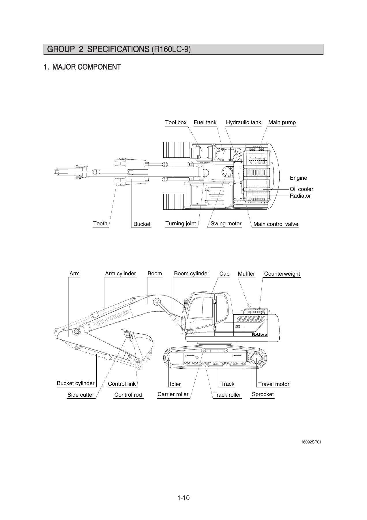
- Section 1 – General: Safety, specifications for the machine and major components
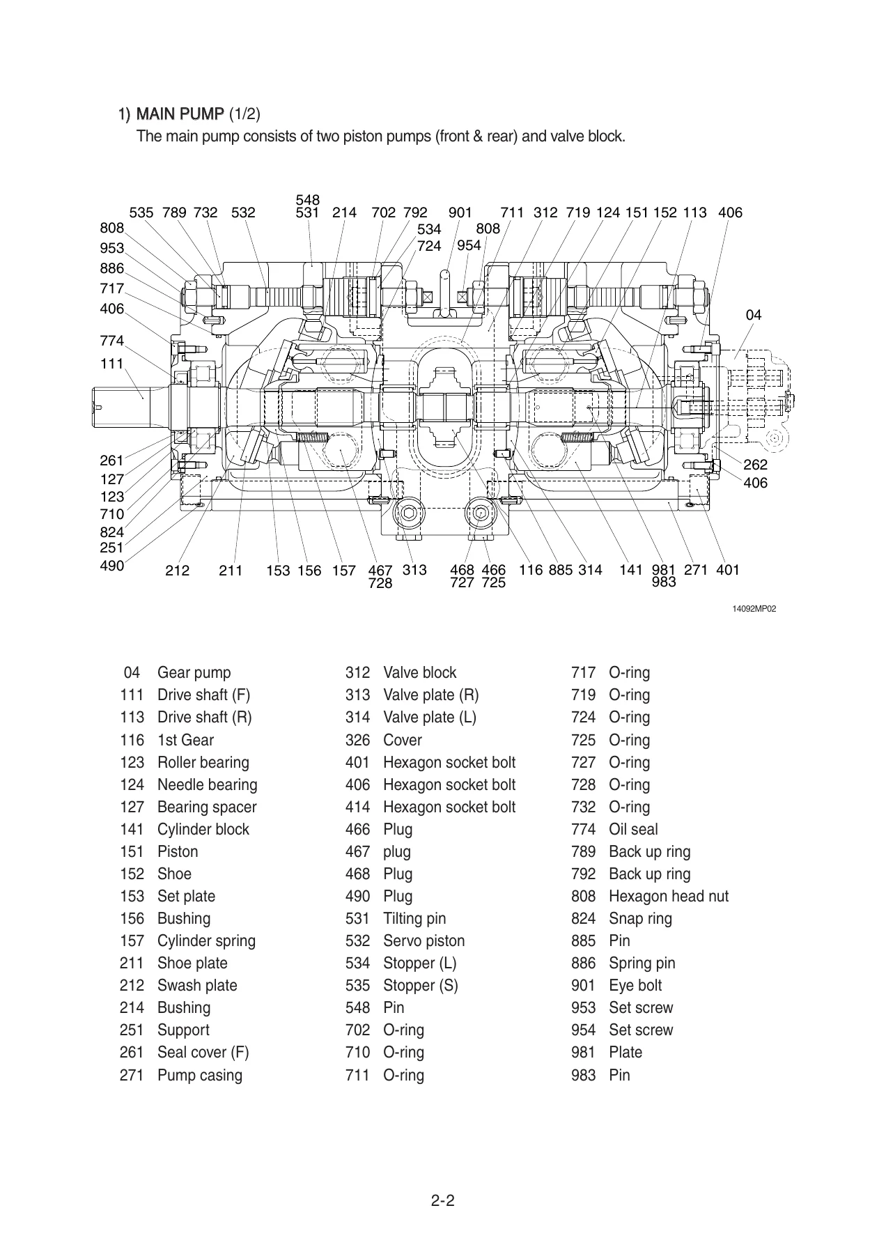
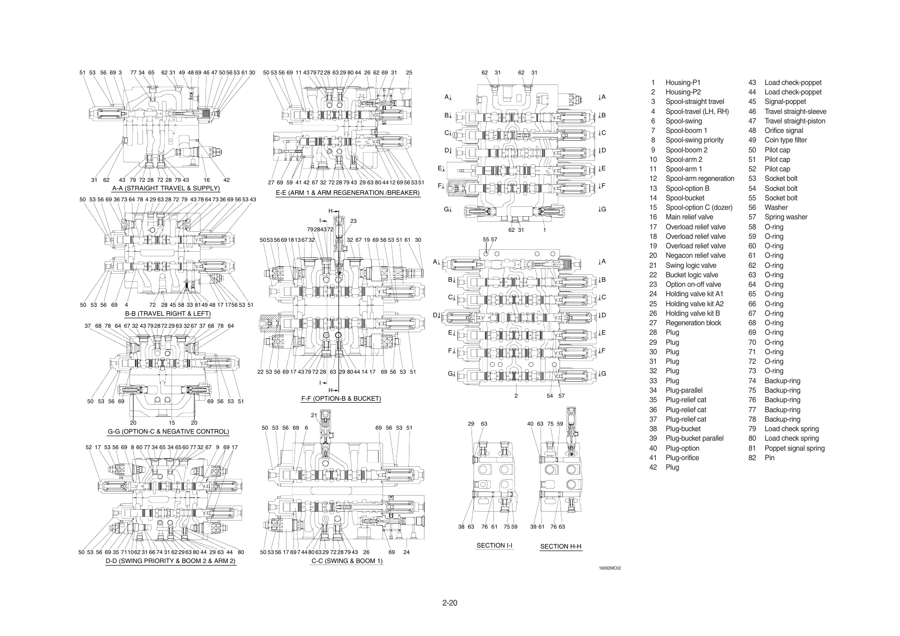
- Section 2 – Structure and Function: Pump Device, Main Control Valve, Swing Device, Travel Device, RCV Lever, RCV Pedal
- Section 3 – Hydraulic System: Hydraulic Circuit, Main Circuit, Pilot Circuit, Single Operation, Combined Operation
- Section 4 – Electrical System: Component Location, Electrical Circuit, Electrical Component Specification, Connectors
- Section 5 – Mechatronics System: Mode Selection, Automatic Deceleration, Power Boost, Travel Speed Control, Automatic Warming Up, Engine Overheat Prevention, Variable Power Control, Attachment Flow Control, Anti-Restart, Self-Diagnostic, Engine Control, EPPR Valve, Monitoring System, Fuel Warmer
- Section 6 – Troubleshooting: Before Troubleshooting, Hydraulic and Mechanical System, Electrical System, Mechatronics System
- Section 7 – Maintenance Standard: Operational Performance Test, Major Components, Track and Work Equipment
- Section 8 – Disassembly and Assembly: Precautions, Tightening Torque, Pump Device, Main Control Valve, Swing Device, Travel Device, RCV Lever, Turning Joint, Boom/Arm/Bucket Cylinders, Undercarriage, Work Equipment
- Section 9 – Component Mounting Torque: Engine System, Electric System, Hydraulic System, Undercarriage, Structure, Work Equipment
IMAGES PREVIEW
What makes this manual worth owning is how far it goes past the parts diagram stage. It pairs the theory of each system with the actual service procedure that follows it: flow-regulator and horsepower-control behaviour inside the pump is explained before you ever open the regulator, the swing and travel motors are broken down to their internal check, brake and counterbalance components, and the mechatronics section maps the MCU, ECM and cluster fault codes to the wiring checks that clear them. That combination – function, fault, fix – is what a working technician actually needs in one document.
Hydraulic and Mechanical Coverage
Section 3 follows the oil from the pumps through the main control valve into every actuator. Neutral bypass flow, straight-travel operation, boom up and boom down with boom regeneration, arm in and arm out with regeneration cut, bucket in and out, swing with priority logic, dozer operation and negative relief valve control are each traced through the spools. Section 6 then turns that circuit knowledge into a diagnostic tool, with step-by-step cause and remedy trees for weak travel, no swing, drifting cylinders, low boom and arm speed, cavitation, overheated hydraulic oil, and cloudy or contaminated oil.
Electrical and Mechatronics Coverage
The electrical section documents component locations inside the cab and on the frame, the full electrical circuit, connector destination tables with part numbers, and electrical component specifications including the battery, battery relay, glow plug relay, start key, pressure sensors and resistor values. On top of that, the ADVANCED CAPO mechatronics group explains the power mode system (P, S, E), work modes, user mode, auto deceleration, power boost, travel speed control, warming up, overheat prevention, anti-restart and self-diagnostic fault tables – including machine error codes and engine fault codes with SPN/FMI references.
Troubleshooting Made Specific
Rather than generic repair advice, the troubleshooting chapters follow the actual failure progression. An engine that starts but the machine will not move sends the technician down a specific chain of checks – oil level, pump noise, pilot pump pressure, pilot piping, gear pump delivery. No swing in both directions, no swing in one direction, swing that will not stop, drift on a slope, curved travel, powerless travel, weak attachment power, boom squeaking and cylinder internal leakage each have their own flowchart with corrective actions. Electrical troubleshooting covers no monitor display, communication errors, charging lamp, coolant overheat lamp, air cleaner lamp, engine oil pressure lamp, hydraulic oil overheat lamp, safety solenoid, travel speed solenoids, engine start failure, wiper motor, head lamp and work lamp.
Maintenance Standards and Tests
Section 7 is the shop-floor reference: engine speed at each power mode, travel speed, track revolution speed, travel deviation, swing speed, swing drift, swing bearing play, cylinder cycle times, dig function drift, control lever operating force and stroke, pilot primary pressure, travel speed selecting pressure, swing parking brake releasing pressure, main pump delivery pressure and system relief settings – each with standard values, allowable limits and measurement procedure.
Disassembly and Assembly
Section 8 gives the practical rebuild side of the job. Pump, regulator, main control valve, swing motor, swing reduction gear, travel motor, travel reduction gear, RCV lever, RCV pedal, turning joint, boom/arm/bucket/dozer cylinders, idler and recoil spring, track link, carrier roller, track roller, bucket, arm and boom each have their removal, disassembly, inspection, assembly and installation procedure with tightening torques and structure cross-sections. Section 9 closes the manual with a full bolt torque lookup by component and by thread size.
What This Manual Enables You To Do
With the Hyundai R160LC-9 R180LC-9 Crawler Excavator Service Repair Manual on hand, a technician or owner-operator can troubleshoot hydraulic, electrical and mechatronics faults to the component level, run the machine against published operational performance standards, disassemble and rebuild the pump, control valve, swing device, travel device and cylinders, and torque every fastener back to specification. Using the correct relief pressures, tightening torques and diagnostic logic prevents the kind of guesswork that damages spools, scoring cylinder bores, or masking a fault by replacing parts that were never the problem.
Delivery is instant. After purchase, the PDF is available immediately for download – no shipping, no waiting, no physical media. Open it in any PDF reader on a laptop, desktop, tablet or smartphone, print the pages you need for the workshop, and keep the rest of the manual on hand for the next job.

Reviews
There are no reviews yet.