
Hyundai R220LC-7 Service Manual PDF – ROBEX 220LC-7 Excavator Repair & Workshop Guide (Long Reach Included)
Original price was: $55.95.$34.95Current price is: $34.95.
Complete Hyundai R220LC-7 Service Manual PDF for the ROBEX 220LC-7 and R220LC-7 Long Reach excavators. 495 pages covering hydraulics, electrical, mechatronics, troubleshooting, maintenance standards, full disassembly/assembly and component torque values.
Description
Hyundai R220LC-7 Service Manual — Full PDF Workshop Guide for the ROBEX 220LC-7 Excavator
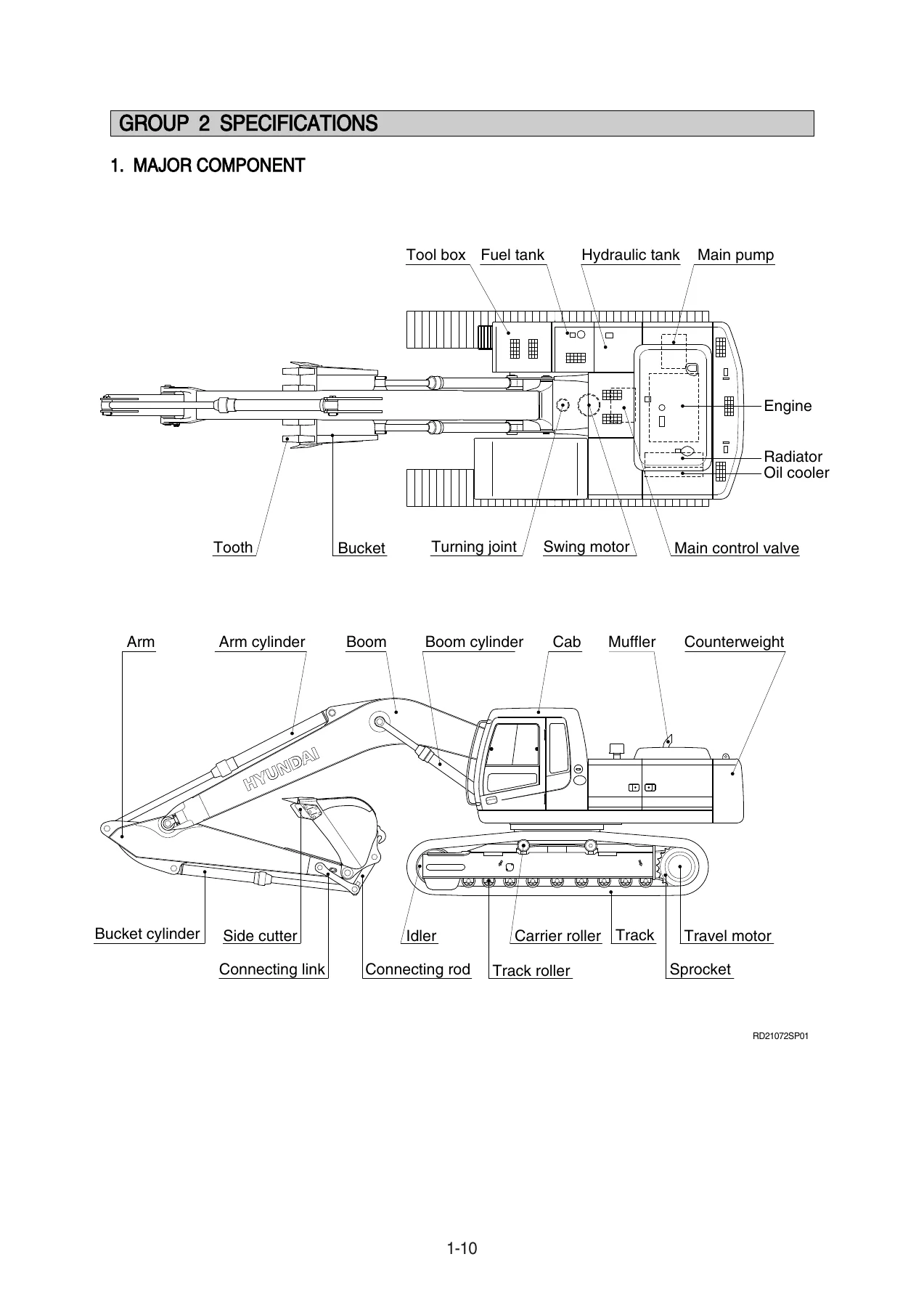
This Hyundai R220LC-7 Service Manual is the complete workshop document for the ROBEX 220LC-7 crawler excavator and its R220LC-7 Long Reach variant, delivered as a single downloadable PDF. It was written for the service workshop: every procedure is laid out in the order a technician actually works, from a machine specification check through to the disassembly, inspection and reassembly of the pump, control valve, swing and travel motors, cylinders, turning joint and undercarriage. If you maintain, diagnose or overhaul an R220LC-7, this is the reference that stays open on the bench.
File Details
- Manual type: Service Manual (Workshop Manual)
- Brand: Hyundai
- Models covered: R220LC-7 (ROBEX 220LC-7) and R220LC-7 Long Reach
- Language: English
- Page count: 495 pages
- File format: PDF
- Sections: Nine numbered sections, Groups 1–11 within the assembly section
Chapters Covered
- Section 1 — General
- Section 2 — Structure and Function
- Section 3 — Hydraulic System
- Section 4 — Electrical System
- Section 5 — Mechatronics System
- Section 6 — Troubleshooting
- Section 7 — Maintenance Standard
- Section 8 — Disassembly and Assembly
- Section 9 — Component Mounting Torque
Section 1 — General
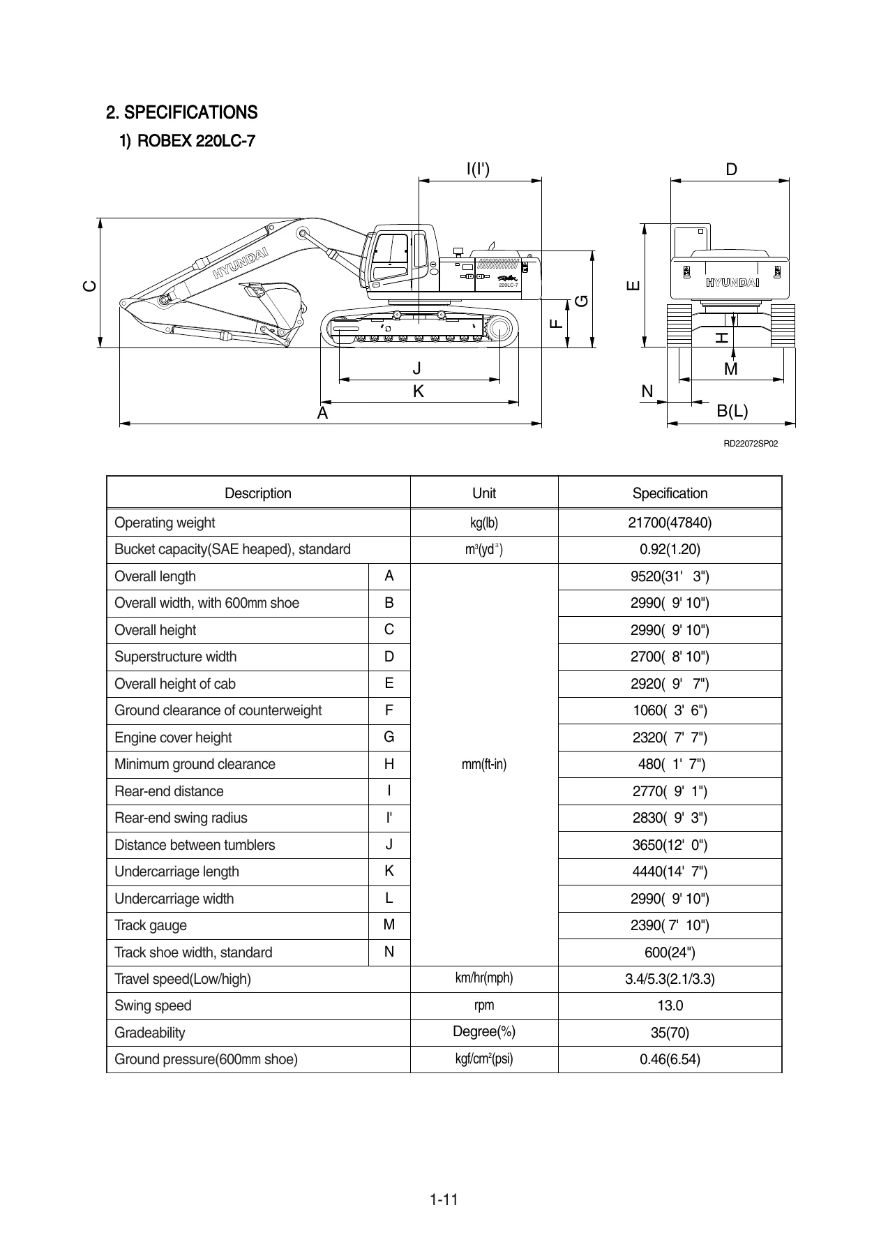
Machine specification tables for both the standard R220LC-7 and the Long Reach version, including operating weight, bucket capacity, overall dimensions, undercarriage data, travel and swing speeds, gradeability and ground pressure. Component weights are broken out by assembly so you know what you are lifting. Working range charts cover the 5.68 m boom with 2.00 m, 2.40 m, 2.92 m and 3.90 m arms, plus the 8.2 m long-reach boom with the 6.3 m arm. Bucket digging force and arm crowd force figures are listed for SAE and ISO ratings, with and without power boost. The section also includes lifting capacity tables, bucket selection guide, undercarriage shoe selection, and the full specification sheet for major components — Cummins 6BTAA engine, main pump, gear pump, main control valve, swing motor, travel motor, RCV lever, RCV pedal, cylinders, track shoes and buckets. Recommended oil and fluid capacities are laid out by service point.
Section 2 — Structure and Function
The theoretical heart of the manual. The pump device is split out into the main pump, the regulator and the gear pump, with an exploded parts view, a port-name table and a detailed explanation of the rotary group, swash plate group and valve block group. Regulator function is explained in depth: negative flow control, total horsepower control, power shift control, Qmax cut control, plus the adjustment procedures for maximum flow, minimum flow, flow control characteristic, outer spring, inner spring and Qmax cut flow. The main control valve section covers the 9-spool monoblock with port tables, tightening torques, spool-by-spool hydraulic circuits and every control function — neutral, travel forward/reverse, travel straight, boom up/down, holding valve, bucket in/out, swing left/right, arm in/out, arm regeneration, swing priority, option B, bucket summation, negative relief, main relief and overload relief. Swing device, travel device, RCV lever and RCV pedal are each given their own structure-and-function treatment, including principles of drive force generation, relief valve operation, parking brake logic, make-up check valve, anti-inversion valve, plowing switch and automatic two-speed switching.
Section 3 — Hydraulic System
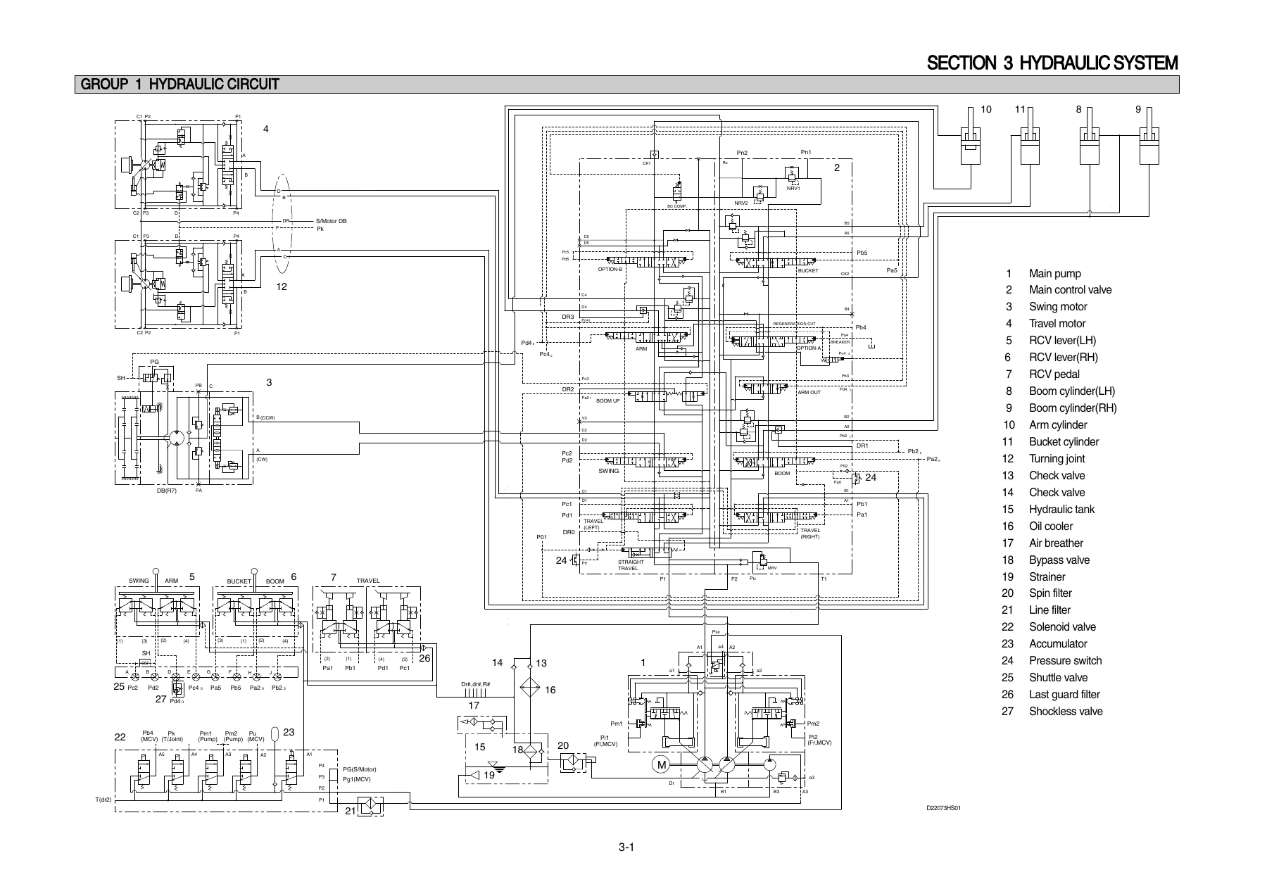
Full hydraulic circuit treatment: suction and delivery circuit, return circuit with bypass check valves and full-flow filter, drain circuit for travel motor, swing motor and main pump, and the complete pilot circuit. Individual subsections walk through the safety valve, swing priority system, travel speed control system, main relief pressure change system, max flow cut-off and swing parking brake release. Single-operation circuit diagrams cover boom up, boom down, arm roll in, arm roll out, bucket roll in, bucket roll out, swing and travel forward/reverse. Combined-operation diagrams cover swing + boom, swing + arm, swing + bucket, the four-function combination, swing + travel, boom + travel, arm + travel and bucket + travel, with straight-travel spool behaviour explained.
Section 4 — Electrical System
Component locations for the cab, engine compartment and frame, followed by the electrical circuit walkthroughs: power circuit, starting circuit, charging circuit, head and work light circuit, beacon and cab light circuit, wiper and washer circuit, and the controller circuit. Electrical component specifications give the check procedures for battery, battery relay, start key, pressure switches, temperature sensors, air cleaner switch, fuel sender, tacho sensor, relays, accel actuator, solenoid valves, EPPR valve, resistor, speakers, switches, starter, alternator, aircon compressor, accel dial, transducers, DC/DC converter, blower motor, aircon resistor, preheater relay, preheater and fusible link. Connector destination tables list every CN-numbered connector with type, pin count, destination and part numbers, followed by a full connector-type reference section covering PA, J, SWP, CN, 375 fasten, AMP Econoseal, AMP Timer, AMP 040/070 Multilock, AMP Fastin-Faston, KET 090/090 WP/SDL, Deutsch DT, Molex, ITT SWF, MWP, Metri-Pack and Deutsch HD30 types.
Section 5 — Mechatronics System
The NEW CAPO (Computer Aided Power Optimization) system is documented end to end: outline, mode selection system (power mode selection, work mode selection and user mode selection with MI/MII memory sets), automatic deceleration system, power boost system, travel speed control system, automatic warming up function, engine overheat prevention function, anti-restart system, self-diagnostic system with current and recorded error display, a full error-code table, engine control system, ROM exchange procedure, accel actuator cable setting, engine speed sensor installation and inspection, CPU controller LED diagnostics, and the EPPR valve — including composition, operating principle, mode-by-mode pressure and current values, version switching (5.x ↔ 6.x), and the electric and pressure check procedures.
Section 6 — Troubleshooting
Fault-finding charts for the hydraulic and mechanical system, the electrical system and the mechatronics system. Hydraulic and mechanical topics include unusual noise from the pump connection, engine starts but machine does not operate, cloudy hydraulic oil, abnormal oil temperature rise, cavitation, contaminated oil, swing system faults (both directions, one direction, low speed, no stop, drift on slope), travel system faults (no travel on one side, curve travel, no stop on slope, powerless travel, runaway on slope, combined travel and attachment faults), and attachment faults (boom/arm/bucket inoperative, low speed, cylinder drift, weak power, bucket totally inoperative, boom squeak). Electrical troubleshooting covers monitor panel not appearing, communication error Co:Er, battery charging warning, coolant overheat, air cleaner warning, engine oil pressure warning, hydraulic oil temperature warning, coolant level warning, coolant temperature gauge, fuel gauge, safety solenoid, travel speed 1/2, engine will not start, key-on no electrics, wiper motor and head/work lamp faults. Mechatronics topics include slow actuators, slow engine speed across all modes, engine stall, cluster or mode selection malfunction, slow engine speed change, auto decel system, warming-up malfunction and power max malfunction — with TEST procedures, expected resistances and expected voltages listed for each.
Section 7 — Maintenance Standard
Operational performance test procedures with standard and maximum allowable values for engine speed, travel speed, track revolution speed, travel deviation, swing speed, swing drift, swing bearing play, hydraulic cylinder cycle time, dig function drift, control lever operating force, control lever stroke, pilot primary pressure, travel speed selecting pressure, swing parking brake releasing pressure, main pump delivery pressure and system pressure regulator relief setting. Maintenance standards for major components cover the main pump, main control valve, swing device, travel motor, RCV lever, RCV pedal, turning joint and cylinders, with wear limits, recommended replacement values, sliding surface roughness and countermeasures. Track and work equipment standards cover track roller, carrier roller, idler, track, track frame and recoil spring, plus work equipment pin and bushing wear limits.
Section 8 — Disassembly and Assembly
The largest working section of the manual, covering precautions, tightening torques, and the full removal/installation and disassembly/assembly sequence for: pump device and regulator; main control valve (spool removal, holding valve, load check, negative relief, main relief and overload relief, assembly of main spool, holding valve and relief valves); swing motor and swing reduction gear; travel motor and travel reduction gear; RCV lever; turning joint; boom, arm and bucket cylinders; undercarriage (track link, carrier roller, track roller, idler, recoil spring); and work equipment (bucket assembly, arm assembly and boom). Each component is documented with structure, tool lists, tightening torque tables, step-by-step disassembly and assembly instructions and re-assembly cautions — including air-bleed procedures and how to check internal cylinder leakage.
Section 9 — Component Mounting Torque
The component mounting torque reference, grouped by engine system, electric system, hydraulic system, undercarriage, structure and work equipment, with bolt sizes and torque values in kgf·m and lbf·ft, plus the standard bolt-and-nut and fitting torque charts.
What This Hyundai R220LC-7 Service Manual Lets You Do
With this service manual in hand you can carry out the full range of professional work on the R220LC-7 and R220LC-7 Long Reach: diagnose a slow or drifting swing, a travel circuit that will not track straight, a boom or arm that loses position under load, an engine that stalls under hydraulic demand, or a Co:Er communication fault on the cluster. You can pull and rebuild the main pump, the regulator, the 9-spool main control valve, the swing motor, the swing reduction gear, the travel motor, the travel reduction gear, the RCV lever, the turning joint and every cylinder on the machine. You can read the mechatronics system properly — mode selection, auto decel, power boost, warming up, overheat prevention, anti-restart and the self-diagnostic error codes — so faults are pinned down by code and by test value rather than by guesswork. You can reference exact wear limits and service standards when inspecting disassembled parts, and you can torque every fastener to the specification the machine was built to.
Why does this matter? Because on a 21,700 kg class excavator, an incorrectly shimmed servo piston, a mis-set EPPR pressure, a distorted relief valve seat or a coupling hub re-tightened to feel rather than to spec does not simply cost a component — it takes out the pump, the engine or the whole hydraulic circuit with it. The R220LC-7 factory values in this book — main relief 330 kgf/cm² (360 with power boost), overload relief 390 kgf/cm², swing relief 240 kgf/cm², travel relief 330 kgf/cm², and the tolerances and clearances behind every one of them — are what keep those repairs on target. The troubleshooting charts lead you to a cause instead of a parts swap, and the disassembly/assembly procedures tell you the sequence, the special tools and the cautions before you strip the component rather than after.
IMAGES PREVIEW
Delivery is immediate. Once payment is confirmed, the file is available for download straight from your account — no shipping, no waiting on a parcel, no damaged paper copy. The PDF opens on any device: workshop laptop, tablet on the machine, or desktop PC in the office. Print the pages you need for the job in front of you, or keep the whole document open for reference through a full teardown. Nothing else needs to be installed, and there is no subscription, licence or expiry — the manual is yours to keep and reuse on every R220LC-7 job that comes through the workshop.
Reviews
There are no reviews yet.