
Hyundai ROBEX 160LC-3 Hydraulic Excavator Service Repair Manual – PDF Download
Original price was: $39.95.$24.95Current price is: $24.95.
Complete Hyundai ROBEX 160LC-3 / R160LC-3 hydraulic excavator service repair manual in PDF. Covers structure and function, hydraulics, electrical, CAPO-III mechatronics, troubleshooting, maintenance standards, and full disassembly and assembly procedures.
Description
The Hyundai ROBEX 160LC-3 Service Repair Manual is the complete workshop reference for the R160LC-3 hydraulic excavator, built for the technician who has to diagnose a fault, judge a worn part, or pull a pump and put it back correctly. It opens with general safety and machine specifications, then moves through structure and function, the hydraulic and electrical systems, the CAPO-III mechatronics system, troubleshooting charts, maintenance standards, and finally full disassembly and assembly procedures for every major component.
File Details
- Manual type: Service Repair Manual (workshop service manual)
- Brand: Hyundai
- Model: ROBEX 160LC-3 / R160LC-3
- Engine: Cummins B3.9-C
- Language: English
- Format: PDF
- Pages: 459
Chapters Covered
This Hyundai ROBEX 160LC-3 service repair manual is divided into eight numbered sections, with each section further split into groups.
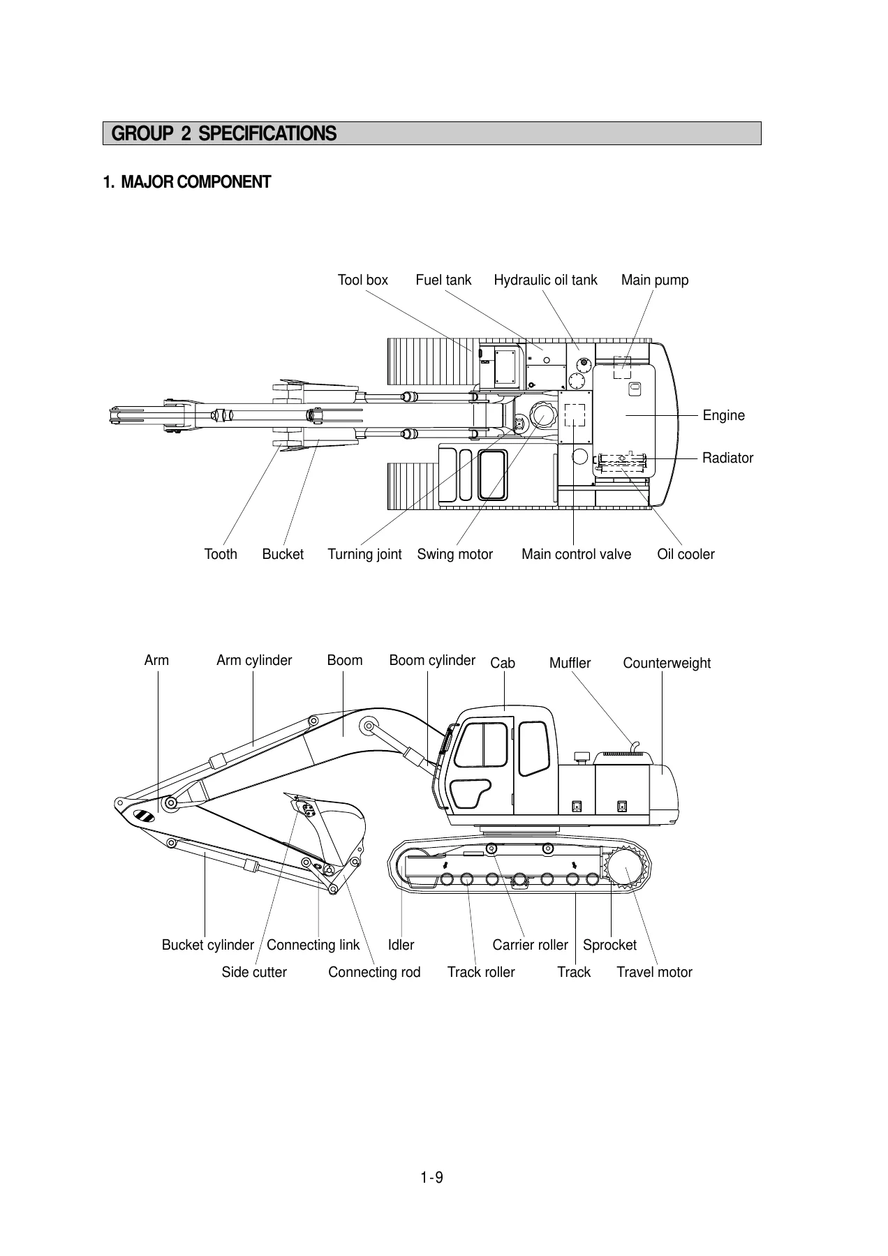
- Section 1 – General: safety hints, machine and major component specifications, conversion tables, working range, weight, lifting capacities, bucket selection guide, undercarriage, specifications for major components, recommended oils
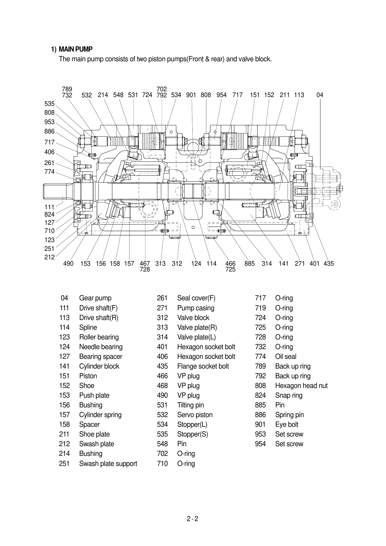
- Section 2 – Structure and Function: pump device, main pump, regulator, gear pump, main control valve, swing device, travel device, RCV lever, RCV pedal, turning joint, cylinders, hydraulic and pilot circuits
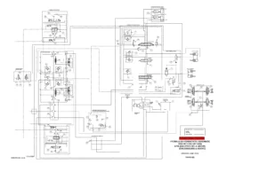
- Section 3 – Hydraulic System: hydraulic circuit, single and combined operation
- Section 4 – Electrical System: electrical circuit, monitoring system, each component, connector destination and connection tables
- Section 5 – Mechatronics System: CAPO-III system, pump control by engine speed sensing, power modes H / S / L / F, auto deceleration, power boost, travel speed control, automatic warming up, engine overheat prevention, arm half flow, anti-restart, self-diagnostic and monitoring system
- Section 6 – Troubleshooting: troubleshooting charts correlating problems to causes across the hydraulic and mechanical, electrical, and mechatronics systems
- Section 7 – Maintenance Standard: operational performance tests, major component standards and service limits, track and work equipment standards
- Section 8 – Disassembly and Assembly: precautions, tightening torque, pump device, regulator, main control valve, swing device, travel device, RCV lever, RCV pedal, turning joint, boom / arm / bucket cylinders, undercarriage, work equipment
Read end to end, the manual gives a technician a working picture of the whole machine: how the tandem piston pump and its regulator behave under load, how the main control valve sums and prioritises flow, how the swing and travel circuits release their brakes, and how the CAPO-III controller manages engine and pump power together. It is the reference you use before you touch a component, not after.
Specifications, Capacities and Working Range
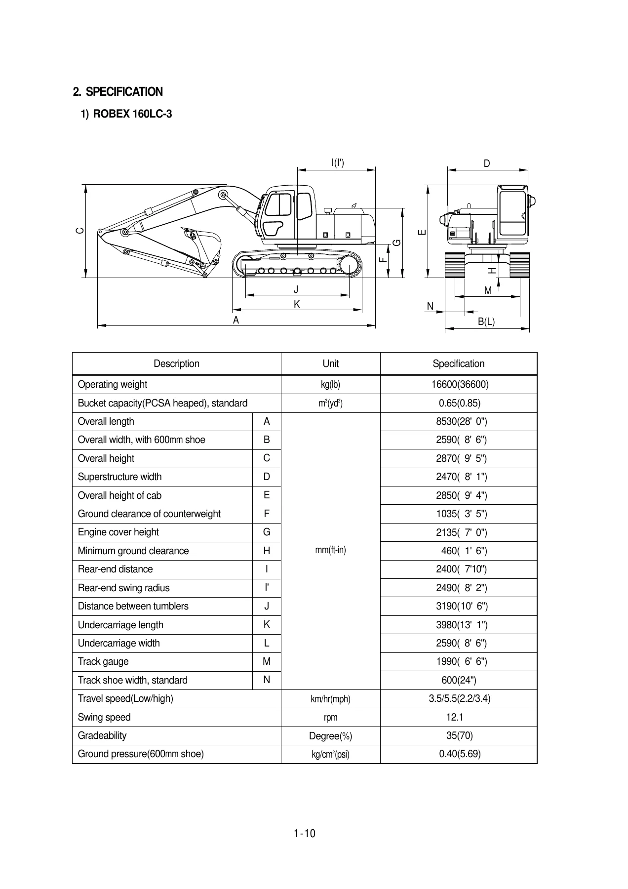
The general section lists the ROBEX 160LC-3 operating weight, standard bucket capacity, overall dimensions, undercarriage and track shoe data, travel and swing speeds, gradeability, and ground pressure for each shoe width. Working range charts are given for the 5.10 m boom with 2.25 m, 2.60 m and 3.10 m arms, including maximum digging reach, digging depth, vertical wall digging depth, digging height, dumping height, minimum swing radius, and bucket and arm crowd forces in both SAE and ISO ratings. Lifting capacity tables follow for the same boom and arm combinations.
Component specifications are listed individually for the engine, main pump, gear pump, main control valve, swing motor, travel motor, remote control valve, cylinders, shoe and bucket, so you can confirm a value before condemning a part.
Hydraulic and Pilot Circuits
The hydraulic system is documented from the suction, delivery, return and drain circuits up to the combined operations. Individual circuit descriptions cover bucket flow summation, swing priority, boom raise and boom down, arm roll in and roll out, bucket roll in and roll out, swing, travel forward and reverse, and the combined operations including swing with boom, swing with arm, swing with bucket, swing with travel, boom with travel, arm with travel and bucket with travel. Valve-level explanations are provided for plunger operation, foot relief valve, centre bypass valve, main relief valve, overload relief valve, arm regeneration, arm holding valve and boom holding valve.
The pilot circuit group explains the safety solenoid valve, main relief pressure change circuit, swing parking brake release, arm half flow system and travel speed control pressure, so the interaction between the pilot side and the main circuit is not left to guesswork.
Electrical System and CAPO-III Mechatronics
The electrical section gives the power circuit, starting circuit, charging circuit, head and work light circuit, beacon lamp circuit, wiper and washer circuit, and controller circuit, followed by electrical component specifications with resistance and contact checks. Connector destination tables and connection tables for the 58-L, multilock, PA, 58-X, J, SWP, CN, BS, LC and 375 fasten type connectors are included.
The mechatronics section explains how the CAPO-III system controls engine and pump power together. Mode selection, auto deceleration, power boost, travel speed control, automatic warming up, engine overheat prevention, arm half flow and anti-restart are each described with their logic tables and limits. Self-diagnostic coverage explains current error and recorded error display, error code deletion, and the full error codes table from Err : 00 through Err : 47. The monitoring system group covers cluster functions, monitoring display groups, tachometer, clock, fuel gauge, coolant temperature gauge, and every warning lamp on the panel.
Troubleshooting
The troubleshooting section is organised by symptom rather than by component, which is how a fault actually presents itself in the yard. Drive system, hydraulic system, swing system, travel system and attachment system each have their own fault trees, covering problems such as unusual noise from the pump connection, the machine not operating at all, cloudy or overheated hydraulic oil, cavitation, contaminated oil, impossible or slow swing, swing drift on a slope, travel failure on one side, curved travel, powerless travel, runaway travel on a slope, and weak or self-lowering boom, arm and bucket cylinders. Electrical troubleshooting follows the same approach for a blank monitor panel, communication errors, charging lamp faults, coolant overheat, air cleaner, engine oil pressure, hydraulic oil temperature and coolant level warnings, gauge faults, safety solenoid, travel speed, starting faults, wiper and work lamps. Mechatronics faults such as slow actuators, slow engine speed, engine stall, cluster or mode selection faults, slow mode change, auto decel failure, warming up faults and power max faults are all covered with test procedures.
Maintenance Standard
The maintenance standard section explains how to carry out performance tests accurately and safely, then gives the standard and maximum allowable values for engine speed, travel speed, track revolution speed, travel deviation, swing speed, swing function drift, swing bearing play, hydraulic cylinder cycle times, dig function drift, control lever operating force, control lever stroke, pilot primary pressure, travel speed selecting pressure, power boost pressure, swing parking brake releasing pressure, main pump delivery pressure, and system pressure regulator relief setting. Major component standards follow for the main pump, main control valve, swing device, travel device and reduction gear, with recommended replacement values and clearances.
Disassembly and Assembly
The final section walks through removal, disassembly, inspection, assembly and installation for the pump device and its main pump and regulator, the main control valve, the swing device including motor and reduction gear, the travel device including motor and reduction gear, the RCV lever and RCV pedal, the turning joint, the boom, arm and bucket cylinders, the undercarriage including track link, carrier roller, track roller, idler and recoil spring, and the work equipment including bucket, arm and boom assemblies. Tightening torque charts for metric coarse and fine thread bolts, pipe and hose fittings, and each component’s own bolt, plug and nut torques are provided throughout so nothing is tightened by feel.
What This Hyundai Excavator Manual Lets You Do
With this Hyundai ROBEX 160LC-3 service repair manual on hand you can carry out scheduled maintenance and adjustment, diagnose hydraulic, electrical and mechatronics faults from a symptom instead of by swapping parts, test pump and relief pressures against the published standard, judge whether a disassembled piston, cylinder bore, valve plate or sprocket is still serviceable or has passed its replacement value, and remove and refit every major assembly on the machine in the correct order with the correct torque.
Correct procedures and correct specifications are what separate a repair that holds from one that comes back. The maintenance standards in this manual give you the wear limits and clearances that tell you when a part is finished, and the troubleshooting charts give you a logical path to the cause instead of a guess.
IMAGES PREVIEW
Delivered as an instant PDF download after payment, with no shipping and no waiting. Read it on a laptop, tablet or phone in the workshop, or print the pages you need for the job in front of you.

Reviews
There are no reviews yet.