
Iveco Trakker ATH-ADH Repair Manual 603.93.389 – Complete PDF Workshop Guide
Original price was: $104.95.$69.95Current price is: $69.95.
The complete Iveco Trakker ATH-ADH Repair Manual, publication 603.93.389, Base — April 2005, delivered as a 1124-page PDF. Sixteen sections covering the F3B engine, ZF gearboxes with Intarder, reduction gear and divider, axles, brakes, steering and electric/electronic system.
Description
Iveco Trakker ATH-ADH Repair Manual — Publication 603.93.389
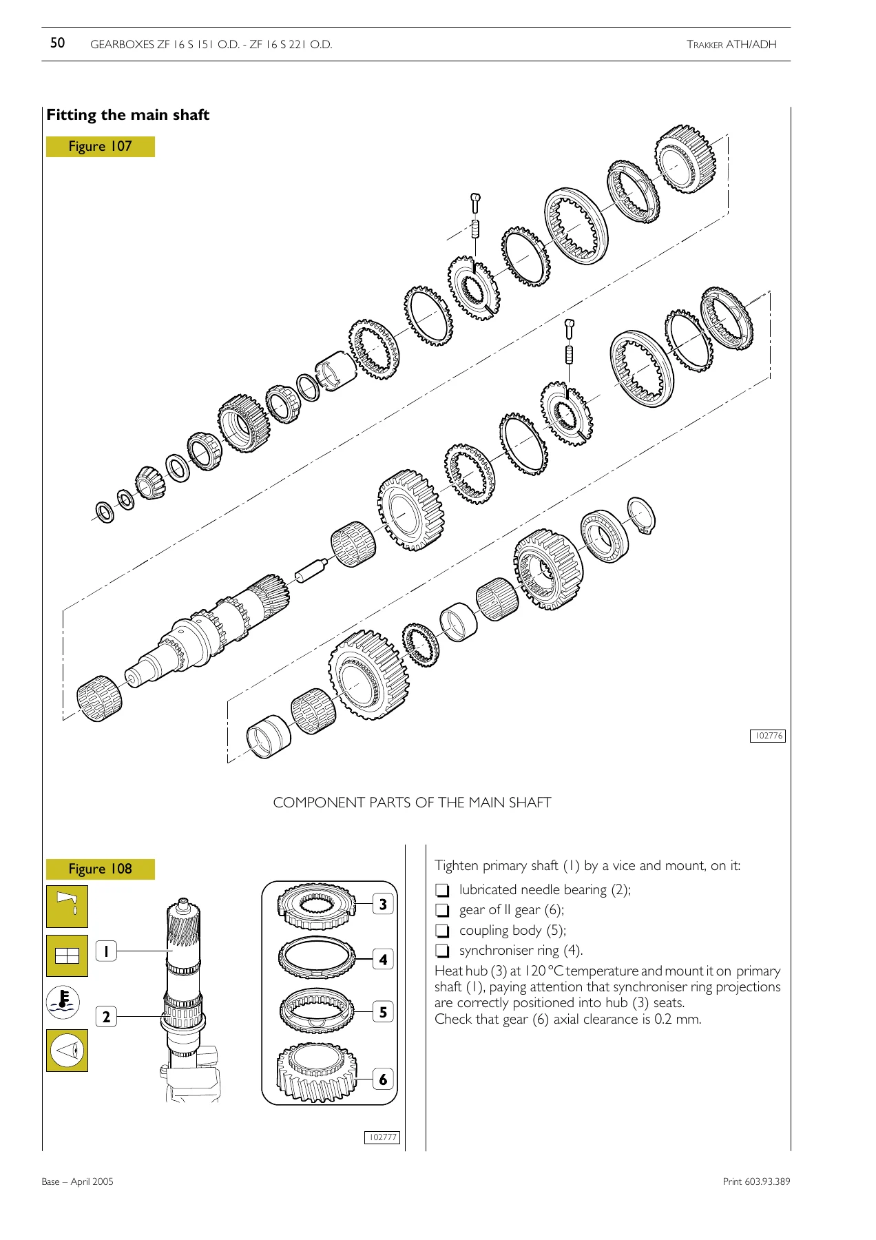
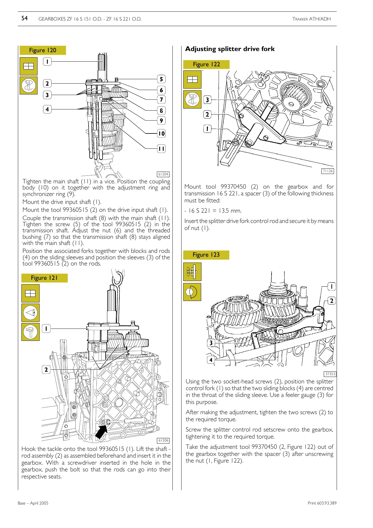
The Iveco Trakker ATH-ADH Repair Manual is the workshop reference for the Trakker ATH/ADH heavy truck, identified by publication number 603.93.389, Base — April 2005, first edition. Running to 1124 pages, this Iveco Trakker ATH-ADH repair manual works through the vehicle section by section, pairing dismantling and reassembly procedures with exploded views, sectional drawings and adjustment diagrams. It covers the F3B engine, the ZF gearboxes with Intarder, the TC 1800-TC 2200 reduction gear and divider, axles, front axles, suspensions, brakes, steering and the electric/electronic system, so the procedure and the drawing for a given job sit together in one document. The manual is addressed to qualified and specialised personnel, and it provides data, characteristics, instructions and methodology to perform repair interventions on the vehicle and its components.
File Details
- Manual type: Repair Manual
- Brand: Iveco
- Model: Trakker ATH-ADH
- Publication number: 603.93.389
- Edition: Base — April 2005, first edition
- Language: English
- Page count: 1124
- File format: PDF
Chapters Covered
- 1 — General information
- 2 — Engines
- 3 — Clutch
- 4 — Gearboxes – Intarder – ZF hydraulic retarder
- 5 — Power take-off
- 6 — Reduction gear – Divider TC 1800-TC 2200
- 7 — Propeller shafts
- 8 — Axles
- 9 — Front axles
- 10 — Suspensions
- 11 — Wheels and tyres
- 12 — Steering gear
- 13 — Pneumatic system – Brakes
- 14 — Bodywork and Chassis frame
- 15 — Scheduled maintenance
- 16 — Electric/electronic system
Section 1 — General information
The opening section sets out the vehicle identification data, including the vehicle identification plate and production identification plate, the commercial coding, the P.I.C. number coding, the composition of the models and the replenishing fluids with their international designations. This is where a technician confirms exactly which ATH/ADH variant is on the ramp before ordering parts or looking up a procedure elsewhere in the manual.
Section 2 — F3B Engine
The F3B engine section opens with views of the engine, a technical description, characteristic curves, general specifications and assembly data with clearances, then tightening torques and diagrams of the tightening sequence for the main engine components. Tools are listed before the removal and refitting procedure and the bench stripping sequence. The repair part covers the cylinder block with checks and measurements, cylinder liners and their replacement, the crankshaft with measurement of the main journals and crankpins, preliminary measurement to select main and big end bearing shells, timing gear and oil pump replacement, checking of main journal assembly clearance and crankshaft end float, the connecting rod and piston assembly, piston rings, connecting rods and bushings. The clearance and torque values are presented with the steps they belong to.
Section 3 — Clutch
Clutch coverage begins with characteristics and data, diagnostics, tightening torques and tools, then moves into removing and refitting the clutch, the checks that go with it, and the thrust bearing procedure. Support bearing replacement on the clutch shaft, the clutch disengagement control, removal and refitting of the pedal assembly and the pedal unit are all documented, along with checking and adjusting the stops on the clutch pedal — clutch stop, idle travel of the clutch pedal and pedal control valve stroke. The hydraulic control side covers the master cylinder and clutch actuator, push rod adjustment for a new clutch, and bleeding air from the clutch hydraulic system.
Section 4 — Gearboxes, Intarder and ZF Hydraulic Retarder
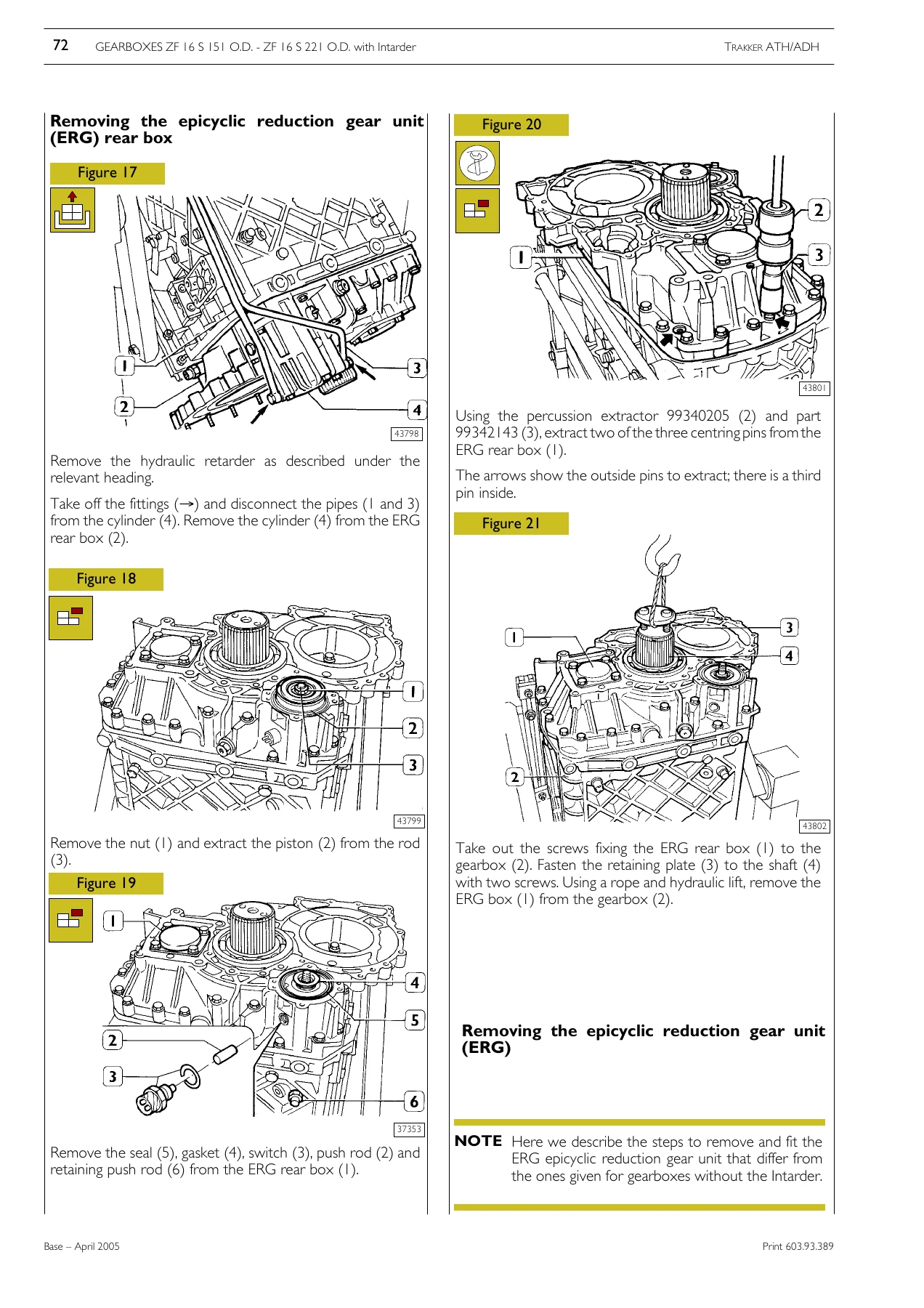
This is one of the most heavily illustrated parts of the manual. It covers the ZF 16 S 151 O.D. and ZF 16 S 221 O.D. gearboxes, and the same gearboxes fitted with the Intarder (IT) hydraulic retarder. Transmission external control is treated separately, as is the Intarder — ZF hydraulic retarder itself. The gearbox work includes removal of the epicyclic reduction gear unit, or ERG, from a gearbox with Intarder, describing the removal and fitting steps that differ from the version without the retarder: taking off the fittings, disconnecting the pipes from the cylinder, removing the cylinder from the ERG rear box, extracting the centring pins with the percussion extractor 99340205 and part 99342143, and removing the ERG rear box from the gearbox using a retaining plate, rope and hydraulic lift. The same section covers removing the ERG rear box seal, gasket, switch, push rod and retaining push rod. These are the jobs where component order and the correct extractor matter, and the drawings show both.
Section 5 — Power take-off
Power take-offs are described as assemblies applicable on vehicles on request. The section covers the ZF – Hydrocar power take-off and the power take-off procedures, giving the technician the reference for fitting and working on this equipment when it is specified on the vehicle.
Section 6 — Reduction gear – Divider TC 1800-TC 2200
The reduction gear and divider section covers the assembly description, specifications and data, the version with P.T.O. (OPT. 391-392) and its specifications, and how the reduction gear-divider is used — on-road driving with the normal ratio and its drive transmission diagram, and off-road driving with the reduced ratio and its own diagram. The torque divider is covered including division ratio calculation and the control locking divider and differential gears. Tightening torques, tools and lubrication are listed, followed by removing and refitting the reduction gear-divider, removing it on the bench, cleaning and checking parts, and replacing the output shaft cover seals.
Section 7 — Propeller shafts
Propeller shaft coverage gives specifications and data for vehicles 4×2, 6×4, 8x4x4, 4×4 and 6×6, followed by fault diagnosis, tightening torques and tools. Removal and refitting of the propeller shaft is documented, as is the repair work on the universal joint — removing and fitting it — and the checks to run on propeller shafts fitted to vehicles.
Section 8 — Axles
The axle section is organised by unit: axles in general, front axles 5985/2D, intermediate axles 453291/2D, and rear axles 451391/2D and 453291/2D. Each unit is treated with its own procedures and data, so the correct axle type is worked on with the correct instructions.
Section 9 — Front axles
Front axles are given their own section, covering front axle 5886/2D and wheel geometry. Wheel geometry is separated out because it is the setting that follows any front axle repair, and having it documented alongside the axle itself makes the sequence straightforward.
Section 10 — Suspensions
Suspension coverage deals with front and rear mechanical suspensions, their description, specifications and data, front and rear shock absorbers, diagnostic, tightening torques and tools. Removal and refitting procedures cover the front leaf spring, the intermediate axle leaf spring on 8×4 vehicles, the rear leaf spring on 4×2 and 4×4 vehicles, and the rear leaf spring on cantilever type suspensions for 6×4, 6×6 and 8×4 vehicles, including assembly of the slipper block and mounting brackets for the longitudinal bars and tightening the U-bolts clamping the leaf spring to the central pivot. The rear cantilever suspension section includes removal and refitting of the central pivot.
Section 11 — Wheels and tyres
Wheels and tyres are covered with a description, specifications and data including tyre pressure values, tools and fault diagnosis. Static wheel balancing and correction of residual static imbalance are documented, along with tyre inflation pressures and how tyre behaviour depends on pressure.
Section 12 — Steering gear
The steering gear section covers the description, specifications and data, diagnostic, tightening torque and equipment. Steering control diagrams are provided for 4×2 and 6×4 vehicles with ZF 8098 power steering, for 4×4 and 6×6 vehicles with ZF 8098 power steering, and for 8x4x4 vehicles with 8099 power steering, together with the steering hydraulic control circuit diagram for 8x4x4 vehicles. The hydraulic guide covers mounting the steering wheel lever, and the removal and refitting of the steering control assembly is described in full. Main operations include bleeding the air from the power steering circuit, measuring plays in the steering box detected on the steering wheel, checking the power steering system maximum pressure and setting the automatic hydraulic steering limit.
Section 13 — Pneumatic system and Brakes
This section opens with the symbols used in air and hydraulic system circuit diagrams, covering miscellaneous components and generators, valves, tanks and accumulators, half-joints and coupling heads, indicators and switches, and brakes. Pipes and couplings are covered, including replacing flexible hoses with threaded couplings and with quick-connection couplings. Braking systems with the EBL device are documented for 4×2 and 4×4 vehicles designed for towing, for 6×4 and 6×6 vehicles designed for towing with the EBL device, for 8x4x4 vehicles isolated with an EBL device, and for 8x4x4 vehicles designed for towing with an EBL device. Braking systems without the EBL device are given their own working schemes for the same vehicle configurations.
Section 14 — Bodywork and Chassis frame
The bodywork and chassis frame section covers the cab with general information, specifications and data, tools and tightening torques, then repair work. The bumper is covered for removal and refitting, and the cabin for removal and refitting. Further procedures include replacing the front shock absorber, replacing the cab suspension front mounting rubber-type bushings, replacing the cab front upper support bushings, removing and refitting the stabiliser bar and replacing the rear cab suspension dampers.
Section 15 — Scheduled maintenance
Scheduled maintenance is set out as its own section, providing the routine service reference that accompanies the repair procedures elsewhere in the manual.
Section 16 — Electric/electronic system
The electric/electronic system section begins with general warnings for electrical and electronic components and the technical codes, then the basic system description with technical and electrical characteristics and the components on the F3B engine. The power network is covered in detail — negative network, mass points, positive network, starting from the driver’s seat and from the engine compartment, cab tilting and lowering, engine stopping from the engine compartment, alternator and starter motor. Connection connectors are listed with their location, together with the connectors list, the rear lights shunt box and wiring harness, the shunt box for the 15-pole and 2×7 pole sockets, the 15-pole and 7-pole sockets for trailer electrical connection, and the diagnosis connector.
Why This Iveco Trakker ATH-ADH Repair Manual Belongs in the Workshop
Work on a truck like the Iveco Trakker ATH-ADH calls for the right sequence and the right values. This Iveco Trakker ATH-ADH repair manual provides the procedures, exploded views and settings for the F3B engine, the ZF gearboxes with Intarder, the TC 1800-TC 2200 reduction gear and divider, the axles and front axles, suspensions, brakes, steering and electric/electronic system, so a job can be planned and carried out against the manufacturer’s own documentation rather than guesswork. The diagnostic material supports fault finding before parts are ordered, and the assembly and adjustment procedures support the repair once the unit is on the bench. For owner-operators, fleet workshops and independent garages, the sixteen sections give a single reference covering both planned maintenance and unplanned repair on this vehicle.
IMAGES PREVIEW
The manual is supplied as an instant PDF download, so there is no shipping to wait for and no physical book to lose in the workshop. It can be opened on a laptop, tablet or phone at the vehicle, printed for the pages needed at the bench, and kept for the life of the truck. Download the Iveco Trakker ATH-ADH repair manual now and put the full repair procedure in front of you before the next job begins.

Reviews
There are no reviews yet.