★ TRUSTED BY 321,897+ PROFESSIONALS WORLDWIDE
🏢
Trusted Business
Verified & Licensed
🛡️
Virus Free Files
100% Safe Downloads
🔒
Secure Payment
SSL Protected
Instant Delivery
Available Immediately
Sale!

JLG E300AJ E300AJP Service & Maintenance Manual 2019 Rev A PDF

Original price was: $39.95.Current price is: $24.95.

Complete JLG service and maintenance manual for E300AJ and E300AJP electric boom lifts. Covers chassis, boom, platform, hydraulics, electrical, JLG Control System diagnostics, torque specs, and repair procedures across 432 pages.

Instant PDF Download
Available immediately
💾
Save to Your Device
Download & keep forever
🛡️
Antivirus Scanned
100% virus-free
🌍
Trusted Worldwide
175,000+ customers

Description

JLG E300AJ E300AJP Service & Maintenance Manual – 2019 Rev A

This JLG E300AJ E300AJP Service & Maintenance Manual is the full workshop document used by technicians to inspect, maintain, troubleshoot, and repair both electric boom lift models. Published October 16, 2019 under part number 31215001, Rev A, it covers everything from daily lubrication to hydraulic cylinder teardown, swing drive overhaul, rotary actuator resealing, and JLG Control System diagnostics.

File Details

  • Manual Type: Service and Maintenance Manual
  • Brand / Manufacturer: JLG
  • Models Covered: E300AJ, E300AJP
  • Document Number: 31215001
  • Revision: Rev A
  • Publication Date: October 16, 2019
  • Language: English
  • Page Count: 432 pages
  • File Format: PDF

Chapters Covered

  • Section A – Introduction: Maintenance Safety Precautions
  • Section 1 – Specifications: Operating Specifications, Capacities, Tires, Dimensional Data, Lubrication Specifications, Critical Stability Weights, Major Component Weights, Operator Maintenance, Thread Locking Compound, Torque Charts (SAE and Metric Fastener)
  • Section 2 – General: Machine Preparation, Inspection and Maintenance, Service and Guidelines, Lubrication and Information, Cylinder Drift, Pins and Composite Bearing Repair Guidelines, Welding on JLG Equipment
  • Section 3 – Chassis: Tires & Wheels, Spindle, Tilt Sensor, Speed Sensor, Drive Hub, Drive Motor, Swing Drive, Swing Motor, Swing Bearing, Battery Maintenance and Charging, Battery Charger, Chassis Tilt Indicator System, Drive Orientation System, Hoods
  • Section 4 – Boom & Platform: Platform Control Enable System, Function Speed Control System, Transport Position Interlock, Above Elevation Cutout, Platform Load Control, Positive Opening Switch Systems, Platform Support, Boom Maintenance, Wear Pads, Tilt Sensor Check, Boom Limit Switches, Articulating Jib Boom, Boom Synchronizing Procedure, Rotary Actuator, Powertrack Maintenance, SkyGuard
  • Section 5 – Basic Hydraulic Information & Schematics: Lubricating O-Rings, Hydraulic Connection Assembly and Torque Specifications (NPTF, BSPT, JIC, SAE, ORFS, MBTL/MBTS, Bulkhead, ORB, MFF, MPP, BSPP, Flange), Hydraulic Cylinders, Cylinder Removal and Installation, Pressure Setting Procedure, Initial Hydraulic Pump Start-Up Procedure, Hydraulic Schematics
  • Section 6 – JLG Control System Analyzer Kit Instructions: Analyzer Connection, Access Levels, Machine Setup, Machine Personality Settings, Diagnostics Menu Structure, System Self Test, Calibrating Steer, Calibrating Tilt Sensor, Calibrating Load Sensing, Diagnostic Trouble Codes
  • Section 7 – Basic Electrical Information & Schematics: Multimeter Basics, Checking Switches, Dielectric Grease Application, AMP Connectors, DEUTSCH Connectors, Wiring Harness Connector Labels, Electrical Harness Diagrams, Electrical Schematics

IMAGES PREVIEW

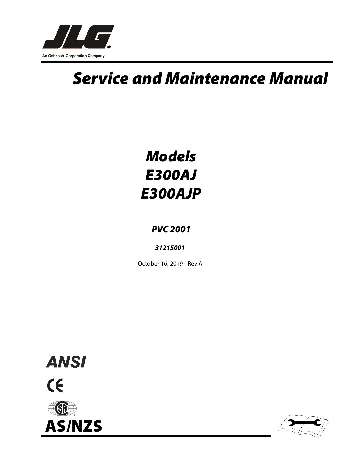
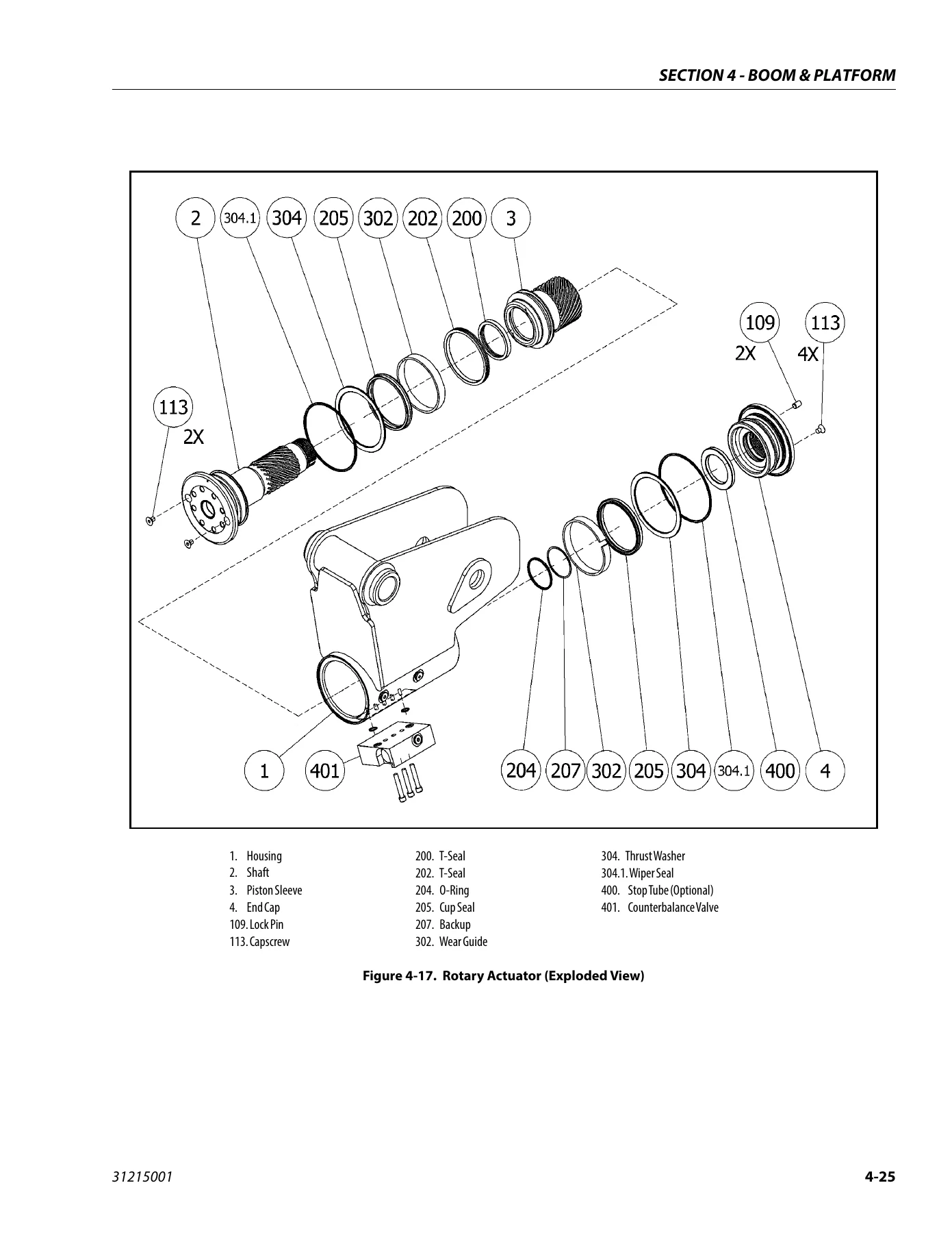
JLG E300AJ E300AJP Service & Maintenance Manual 2019 Rev A PDF — PDF page 1 preview
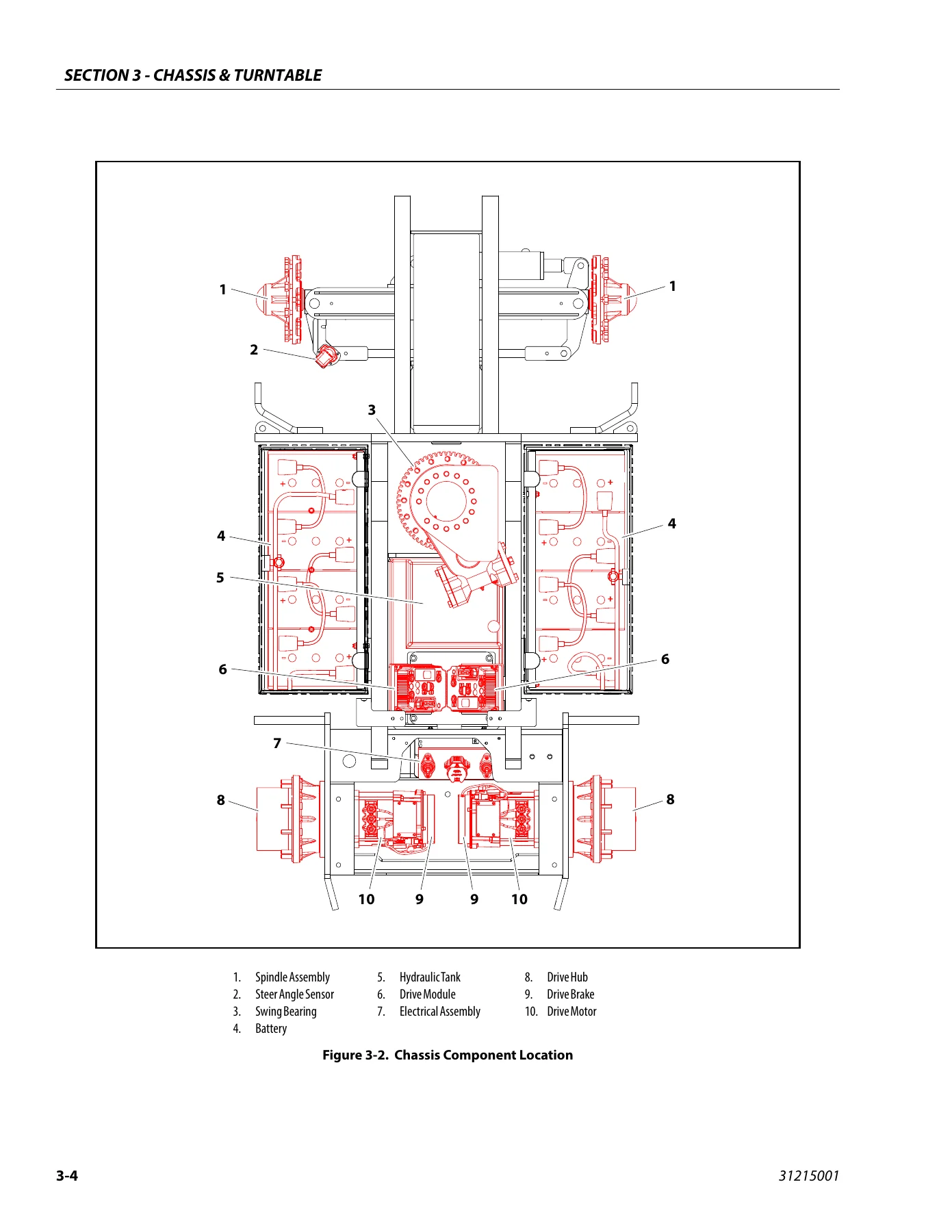
JLG E300AJ E300AJP Service & Maintenance Manual 2019 Rev A PDF — PDF page 48 preview
JLG E300AJ E300AJP Service & Maintenance Manual 2019 Rev A PDF — PDF page 137 preview

This JLG E300AJ E300AJP service manual gives a technician the complete procedural backbone for both electric boom lift models. The specifications chapter alone provides operating data, dimensional measurements, tire and wheel data, hydraulic oil cross-references, critical stability weights, and both SAE and metric torque charts. Beyond that, the document walks through component removal, disassembly, inspection, reassembly, and installation for every major assembly on the machine – chassis, drive hubs, drive motors, swing drive, swing motor, swing bearing, boom sections, telescoping cylinders, the rotary actuator, and the power track.

The hydraulics section is particularly detailed: it includes O-ring lubrication procedures, assembly instructions and torque tables for every fitting standard used on the machine (NPTF, BSPT, JIC, SAE, ORFS, DIN, bulkhead, ORB, MFF, MPP, BSPP, and flange connections), complete teardown and rebuild sequences for each cylinder, pressure-setting procedures for the main valve bank and boom function valve bank, and the initial hydraulic pump start-up procedure after pump or motor replacement.

The electrical and control-system material is equally thorough. Section 6 covers the JLG Control System Analyzer Kit from connecting the handheld unit through changing access levels, adjusting personality settings, machine setup, running the system self-test, calibrating the steer sensor, tilt sensor, and load sensing system, and interpreting diagnostic trouble codes. Section 7 provides multimeter fundamentals, switch testing, dielectric grease application for AMP and DEUTSCH connectors, wiring harness connector labeling, complete harness diagrams, and fourteen sheets of electrical schematics.

What This Manual Enables You To Do

  • Perform scheduled maintenance and lubrication at the correct intervals with the right lubricants and capacities
  • Diagnose and repair chassis, drive, steer, swing, and boom faults using factory procedures
  • Overhaul hydraulic cylinders with correct seal orientation, torque values, and pressure settings
  • Service the swing drive, swing motor, and swing bearing including backlash adjustment and bolt torque sequences
  • Rebuild the rotary actuator with timing-mark alignment and correct seal installation
  • Repair or replace powertrack links, brackets, and rollers
  • Use the JLG Control System Analyzer to access diagnostics, run system tests, and calibrate sensors
  • Trace electrical faults using complete harness diagrams and wiring schematics
  • Set hydraulic relief pressures at the main valve bank and boom function valve bank
  • Check and correct battery charging, battery maintenance, and battery charger fault codes

Complete PDF Bookmark Tree

Complete Bookmarks

The complete bookmarks in the “JLG E300AJ E300AJP Service & Maintenance Manual 2019 Rev A PDF” are as follows:

31215001_A_E300AJ, E300AJP_JLG_Service_Englishp. 3
Section A. Introduction – Maintenance Safety Precautionsp. 3
A Generalp. 3
B Hydraulic System Safetyp. 3
C Maintenancep. 3
Table of Contentsp. 5
List of Figuresp. 11
List of Tablesp. 15
Section 1. Specificationsp. 17
1.1 Operating Specificationsp. 17
Machine Specification E300AJp. 17
Machine Specification E300AJPp. 17
1.2 Capacitiesp. 17
1.3 Tiresp. 17
1.4 Dimensional Datap. 18
1.5 Lubrication Specificationsp. 18
Hydraulic Oilp. 18
1.6 Critical Stability Weightsp. 20
1.7 Major Component Weightsp. 20
1.8 Operator Maintenancep. 22
1. Swing Bearingp. 22
2. Swing Bearing/Worm Gear Teethp. 22
3. Hydraulic Tank Lube Point(s) – Fill Cap Capacity -2.9 Gal. (11 L), 2.1 Gal. ( 8 L) to Full Mark Lube – HO Interval – Check Level daily; Change every 2 years or 1200 hours of operation. Comments – On new machines, those recently overhauled, or afte…p. 23
4. Hydraulic Return Filterp. 23
5. Wheel Drive Hubp. 23
6. Wheel Bearing Lube Point(s) – Repack Capacity – A/R Lube – MPG Interval – Every 2 years or 1200 hours of operationp. 23
1.9 Thread Locking Compoundp. 24
1.10 Torque Chartsp. 25
SAE Fastener Torque Chartp. 25
SAE Fastener Torque Chart (Continued)p. 26
SAE Fastener Torque Chart (Continued)p. 27
SAE Fastener Torque Chart (Continued)p. 28
SAE Fastener Torque Chart (Continued)p. 29
SAE Fastener Torque Chart (Continued)p. 30
Metric Fastener Torque Chartp. 31
Metric Fastener Torque Chart (Continued)p. 32
Metric Fastener Torque Chart (Continued)p. 33
Metric Fastener Torque Chart (Continued)p. 34
Section 2. Generalp. 35
2.1 Machine Preparation, Inspection, and Maintenancep. 35
Generalp. 35
Preparation, Inspection, and Maintenancep. 35
Pre-Start Inspectionp. 35
Pre-Delivery Inspection and Frequent Inspectionp. 35
Annual Machine Inspectionp. 35
Preventative Maintenancep. 35
2.2 Service and Guidelinesp. 36
Generalp. 36
The following information is provided to assist you in the use and application of servicing and maintenance procedures contained in this book.p. 36
Safety and Workmanshipp. 36
Your safety, and that of others, is the first consideration when engaging in the maintenance of equipment. Always be conscious of weight. Never attempt to move heavy parts without the aid of a mechanical device. Do not allow heavy objects to rest in …p. 36
Cleanlinessp. 36
1. The most important single item in preserving the long service life of a machine is to keep dirt and foreign materials out of the vital components. Precautions have been taken to safeguard against this. Shields, covers, seals, and filters are provi…p. 36
2. At any time when air, fuel, or oil lines are disconnected, clear adjacent areas as well as the openings and fittings themselves. As soon as a line or component is disconnected, cap or cover all openings to prevent entry of foreign matter.p. 36
3. Clean and inspect all parts during servicing or maintenance, and assure that all passages and openings are unobstructed. Cover all parts to keep them clean. Be sure all parts are clean before they are installed. New parts should remain in their co…p. 36
Components Removal and Installationp. 36
1. Use adjustable lifting devices, whenever possible, if mechanical assistance is required. All slings (chains, cables, etc.) should be parallel to each other and as near perpendicular as possible to top of part being lifted.p. 36
2. Should it be necessary to remove a component on an angle, keep in mind that the capacity of an eyebolt or similar bracket lessens, as the angle between the supporting structure and the component becomes less than 90 degrees.p. 36
3. If a part resists removal, check to see whether all nuts, bolts, cables, brackets, wiring, etc., have been removed and that no adjacent parts are interfering.p. 36
Component Disassembly and Assemblyp. 37
Pressure-Fit Partsp. 37
Bearingsp. 37
1. When a bearing is removed, cover it to keep out dirt and abrasives. Clean bearings in nonflammable cleaning solvent and allow to drip dry. Compressed air can be used but do not spin the bearing.p. 37
2. Discard bearings if the races and balls (or rollers) are pitted, scored, or burned.p. 37
3. If bearing is found to be serviceable, apply a light coat of oil and wrap it in clean (waxed) paper. Do not unwrap reusable or new bearings until they are ready to install.p. 37
4. Lubricate new or used serviceable bearings before installation. When pressing a bearing into a retainer or bore, apply pressure to the outer race. If the bearing is to be installed on a shaft, apply pressure to the inner race.p. 37
Gasketsp. 37
Bolt Usage and Torque Applicationp. 37
1. Always use new replacement hardware when installing locking fasteners. Use bolts of proper length. A bolt which is too long will bottom before the head is tight against its related part. If a bolt is too short, there will not be enough thread area…p. 37
2. Unless specific torque requirements are given within the text, standard torque values should be used on heat- treated bolts, studs, and steel nuts, in accordance with recommended shop practices. (See Torque Chart Section 1.)p. 37
Hydraulic Lines and Electrical Wiringp. 37
Hydraulic Systemp. 37
1. Keep the system clean. If evidence of metal or rubber particles are found in the hydraulic system, drain and flush the entire system.p. 37
2. Disassemble and reassemble parts on clean work surface. Clean all metal parts with non-flammable cleaning solvent. Lubricate components, as required, to aid assembly.p. 37
Lubricationp. 38
Batteryp. 38
Lubrication and Servicingp. 38
2.3 Lubrication and Informationp. 38
Hydraulic Systemp. 38
1. The primary enemy of a hydraulic system is contamination. Contaminants enter the system by various means, e.g., using inadequate hydraulic oil, allowing moisture, grease, filings, sealing components, sand, etc., to enter when performing maintenanc…p. 38
2. The design and manufacturing tolerances of the component working parts are very close, therefore, even the smallest amount of dirt or foreign matter entering a system can cause wear or damage to the components and generally results in faulty opera…p. 38
3. Cloudy oils indicate a high moisture content which permits organic growth, resulting in oxidation or corrosion. If this condition occurs, the system must be drained, flushed, and refilled with clean oil.p. 38
4. It is not advisable to mix oils of different brands or types, as they may not contain the same required additives or be of comparable viscosities. Good grade mineral oils, with viscosities suited to the ambient temperatures in which the machine is…p. 38
Hydraulic Oilp. 38
1. Refer to Section 1 for recommendations for viscosity ranges.p. 38
2. JLG recommends Premier Hydraulic Fluid (VG 15), which has an SAE viscosity of 10W and a viscosity index of 140.p. 38
Changing Hydraulic Oilp. 38
1. Filter elements must be changed after the first 50 hours of operation and every 300 hours thereafter. If it is necessary to change the oil, use only those oils meeting or exceeding the specifications appearing in this manual. If unable to obtain t…p. 38
2. Use every precaution to keep the hydraulic oil clean. If the oil must be poured from the original container into another, be sure to clean all possible contaminants from the service container. Always clean the mesh element of the filter and replac…p. 38
3. While the unit is shut down, a good preventive maintenance measure is to make a thorough inspection of all hydraulic components, lines, fittings, etc., as well as a functional check of each system, before placing the machine back in service.p. 38
Lubrication Specificationsp. 38
Specified lubricants, as recommended by the component manufacturers, are always the best choice, however, multi-purpose greases usually have the qualities which meet a variety of single purpose grease requirements. Should any question arise, regardin…p. 38
2.4 Cylinder Driftp. 39
Theoryp. 39
Cylinder Leakage Testp. 39
Cylinder Thermal Driftp. 39
2.5 Pins and Composite Bearing Repair Guidelinesp. 40
1. Pinned joints should be disassembled and inspected if the following occurs:p. 40
a. Excessive sloppiness in joints.p. 40
b. Noise originating from the joint during operation.p. 40
2. Filament wound bearings should be replaced if any of the following is observed:p. 40
a. Frayed or separated fibers on the liner surface.p. 40
b. Cracked or damaged liner backing.p. 40
c. Bearings that have moved or spun in their housing.p. 40
d. Debris embedded in liner surface.p. 40
3. Pins should be replaced if any of the following is observed (pin should be properly cleaned prior to inspection):p. 40
a. Detectable wear in the bearing area.p. 40
b. Flaking, pealing, scoring, or scratches on the pin surface.p. 40
c. Rusting of the pin in the bearing area.p. 40
4. Re-assembly of pinned joints using filament wound bearings.p. 40
a. Housing should be blown out to remove all dirt and debris. Bearings and bearing housings must be free of all contamination.p. 40
b. Bearing/pins should be cleaned with a solvent to remove all grease and oil. Filament wound bearing are a dry joint and should not be lubricated unless otherwise instructed (i.e. sheave pins).p. 40
c. Pins should be inspected to ensure it is free of burrs, nicks, and scratches which would damage the bearing during installation and operation.p. 40
2.6 Welding on JLG Equipmentp. 40
Do the Following When Welding on JLG Equipmentp. 40
DO NOT Do the Following When Welding on JLG Equipmentp. 40
Section 3. Chassis & Turntablep. 45
3.1 Tires & Wheelsp. 45
Tire Damagep. 45
Tire Replacementp. 45
Wheel and Tire Replacementp. 45
Wheel Installationp. 45
1. Start all nuts by hand to prevent cross threading. DO NOT use a lubricant on threads or nuts.p. 45
2. Tighten nuts in the following sequence:p. 45
3. The tightening of the nuts should be done in stages. Following the recommended sequence, tighten nuts per wheel torque chart.p. 46
4. Wheel nuts should be torqued after first 50 hours of operation and after each wheel removal. Check the torque after the first 10 miles, 25 miles, and again at 50 miles. Check periodically thereafter.p. 46
3.2 Spindlep. 46
Setting Wheel Bearing End Playp. 46
1. Tighten the spindle nut to assure the bearings are properly seated.p. 46
2. Loosen the spindle nut completely until the nut can be turned by hand.p. 46
3. Tighten the spindle nut by hand using a socket without rotating the hub.p. 46
4. If the cotter pin can be assembled with the spindle nut finger tight, insert cotter pin without backing the nut off. If the cotter pin cannot be assembled with the spindle nut hand tight, tighten the spindle nut to the nearest available slot and i…p. 46
5. Check the unit for end play by moving the hub up & down parallel along the centerline of the spindle. If you can feel excessive end play (over the 0.010" [0.25 mm] specification), recheck the nut to see what is causing the excessive end play. Keep…p. 46
6. The units should be checked visually to make sure the cotter pins are installed and that the correct components have been used. Each unit must also be checked for the proper feel to make sure there isn’t excessive end play and the hubs turn freely.p. 46
7. Insert the dust cap and check to make sure the cotter pin is not going to interfere. Cap must be pressed all the way down. The unit should be checked again to assure it spins freely after the dust cap is installed.p. 46
Specificationsp. 46
Checkingp. 46
1. Hub should rotate freely when spun by hand.p. 46
2. The hub should not be noticeably loose when moved parallel with spindle centerline.p. 46
Greasing Requirementsp. 46
1. Dust Capp. 47
2. Cotter Pinp. 47
3. Spindle Nutp. 47
4. Spindle Washerp. 47
5. Stud Nutp. 47
6. Bearing Conep. 47
7. Hubp. 47
8. Bearing Conep. 47
9. Sealp. 47
10. Spindlep. 47
2. Steer Angle Sensorp. 48
3. Swing Bearingp. 48
4. Batteryp. 48
5. Hydraulic Tankp. 48
6. Drive Modulep. 48
7. Electrical Assemblyp. 48
8. Drive Hubp. 48
9. Drive Brakep. 48
10. Drive Motorp. 48
1. Axle Assemblyp. 49
2. Spindle Assemblyp. 49
3. Tie Rodp. 49
4. Steer Cylinderp. 49
5. Thrust Washerp. 49
6. Thrust Bearingp. 49
7. Sensor Switchp. 49
1. Drive Motorp. 50
2. Motor Sealp. 50
3. Motor Adapterp. 50
4. Hub Sealp. 50
5. Drive Hubp. 50
6. Tire & Wheelp. 50
7. Lug Nutp. 50
8. Drive Brakep. 50
9. Boltp. 50
10. Boltp. 50
11. Boltp. 50
3.3 Tilt Sensorp. 51
3.4 Speed Sensorp. 51
3.5 Drive Hubp. 55
Roll and Leak Testingp. 55
Tightening and Torquing Boltsp. 55
1. Tighten (but do not torque) bolt “A” until snug.p. 55
2. Go to the opposite side of the bolt circle and tighten bolt “B” until equally snug.p. 55
3. Crisscross around the bolt circle and tighten remaining bolts.p. 55
4. Now use a torque wrench to apply the specified torque to bolt “A”.p. 55
5. Using the same sequence, crisscross around the bolt circle and apply an equal torque to the remaining bolts.p. 55
Main Disassemblyp. 56
1. Perform Roll Check and Leak Check if applicable prior to disassembling the unit.p. 56
2. Drain oil from unit. Note the condition and volume of the oil.p. 56
3. Remove Coupling (7) from Spindle End first.p. 56
4. Remove Retaining Ring (6G) by prying the open end of Retaining Ring out of the groove in the Ring Gear (1F) with a screwdriver, then grasp the loose end with pliers and pull the Retaining Ring completely out of the groove.p. 56
5. Remove the Cover Subassembly (6) from the unit. The unit can be carefully pressurized with air to pop the cover out of the unit. Washer (2) may have to be removed separately because of the loose attachment.p. 56
6. Remove the First Stage Sun Gear (10) if applicable.p. 56
7. Remove the Input Carrier Sub-assembly (3).p. 56
8. Remove the Second Stage Sun Gear (11).p. 56
9. Remove the Input Shaft (9).p. 56
10. Remove the Output Stage Carrier Sub-assembly (4).p. 56
11. Loosen and remove the three Flat Head Bolts (19) that retain the Ring Gear (1F) to the Housing (1G).p. 56
12. Lift the Ring Gear (1F) off of the Housing (1G).p. 56
13. Remove the O-Ring (18) from between the Housing (1G) and the Ring Gear (1F).p. 56
Output Carrier Disassemblyp. 58
1. Using a 1/8” diameter punch, drive the Roll Pin (4G) into the Planet Shaft (4E) until it bottoms against the Carrier (3A).p. 58
2. Using a soft face hammer, tap the Planet Shaft (4E) out of the Carrier (4A).p. 58
3. Using a 1/8” diameter punch, drive the Roll Pin (4G) out of the Planet Shaft (4E).p. 58
4. Slide the Planet Gear Sub-assembly (4) out of the Output Carrier (4A) being careful to not drop the Needle Bearings (4C) in the process.p. 58
5. Remove 4 Thrust Washers (4B), 28 Needle Rollers (4C) and the Thrust Spacer (4D) from the Second Stage Planet Gear (4F).p. 58
6. Repeat Steps 1 though 5 for the remaining two Planet Gears (4F).p. 58
7. Remove the Thrust Washer (4H) from the counterbore in the Output Carrier (4A).p. 58
Input Carrier Disassemblyp. 60
1. Using a 1/8” diameter punch, drive the Roll Pin (4G) into the Planet Shaft (3E) until it bottoms against the Carrier (3A).p. 60
2. Using a soft face hammer, tap the Planet Shaft (3E) out of the Carrier (3A).p. 60
3. Using a 1/8” diameter punch, drive the Roll Pin (4G) out of the Planet Shaft (3E).p. 60
4. Slide the Planet Gear (3F) and the two Thrust Washers (3B) out of the Carrier (3A).p. 60
5. Remove the 14 needle Bearings (3C) from the bore of the Planet Gear (3F).p. 60
6. Repeat steps 1 through 5 for each of the two remaining planet gears.p. 60
Hub Spindle Disassemblyp. 61
1. Place unit on bench with Spindle (1A) end down.p. 61
2. Remove Retaining Ring (1J) with appropriate tool.p. 61
3. Remove Spacer (1N).p. 61
4. Remove Bearing Cone (1C) from Bearing Cup (1D) in Hub (1G).p. 61
5. Lift Hub (1G) off of Spindle (1A). Remove Boot Seal (1Q) from Hub (1G) if applicable.p. 61
6. If necessary, press 9 Studs (1H) out of Hub (1G). Locate Hub (1G) on Seal (1B) end.p. 61
7. Remove Seal (1B) from Hub (1G).p. 61
8. Remove Bearing Cone (1E) from Hub (1G).p. 61
9. Using a soft steel rod, knock both Bearing Cups (1D) out of Hub (1G).p. 61
Cover Disassemblyp. 62
1. Remove O-Ring (17) from groove in Cover (6A).p. 62
2. Remove Thrust Washer (2) from Cover (6A) pockets.p. 62
3. Unscrew two Hex Head Bolts (6C) and remove Disengage Cap (6B) from Cover (6A).p. 62
4. Pull Disengage Rod (6D) out from Cover (6A).p. 62
5. Use appropriate tool to remove O-Ring (6E) from internal groove in Cover (6A).p. 62
6. Remove two O-Ring Pipe Plugs (6F) from Cover (6A).p. 62
Input Carrier Assemblyp. 63
1. Apply a liberal coat of grease to the bore of one Input Planet Gear (3F).p. 63
2. Line the inside of the Planet Gear (3F) with 14 Needle Bearings (3C).p. 63
3. Set Carrier (3A) in an upright position.p. 63
4. Insert a Planet Shaft (3E) into the planet shaft hole in the end of the Carrier (3A) opposite the splined end. The end of the planet shaft that does NOT have the roll pin hole should be inserted into the carrier FIRST.p. 63
5. Place one Thrust Washer (3B) onto the end of Planet Shaft (3E). Make sure the flat faces towards the inside of the carrier and make sure the button fits in the pocket on the inside of the Carrier (3A) towards the OD.p. 63
6. Following the thrust washer, place Planet Gear (3F) with needle rollers, onto Planet Shaft (3E).p. 63
7. Following the planet gear, place one more Thrust Washer (3B) onto Planet Shaft (3E). Align the Thrust Washer (3B) in the same manner described in Step 5.p. 63
8. Now insert Planet Shaft (3E) through the opposite planet shaft hole on Carrier (3A). Use an alignment punch or similar tool to align the roll pin holes on Carrier (3A) and Planet Shaft (3E).p. 63
9. Drive Roll Pin (4G) down into the aligned roll pin holes. Pin should be flush with the flat of carrier.p. 63
10. Repeat Steps 1-9 for the installation of the two remaining Planet Gears (3F).p. 63
Output Planet Gear Assemblyp. 63
11. Apply a liberal coat of grease to the bore of one Output Planet Gear (4F).p. 63
12. Line the inside of the Planet Gear (4F) with 14 Needle Bearings (4C).p. 63
13. Place Spacer (4D) into the bore of the Output Planet (4F).p. 63
14. Repeat Step 2 to put in second roll of Needle Rollers (4C).p. 63
15. Apply grease to hold two Thrust Washers (4B) together and onto Output Planet Gear (4F) counterbore. Do the same to the other side.p. 63
16. Repeat Steps 1-5 to finish the assembly of the two remaining Output Planet Gears (4F).p. 63
Output Carrier Assemblyp. 64
1. Place Thrust Washer (4H) into counterbore of Carrier (4A). BE SURE the small diameter side of Washer (4H) facing planet gear side.p. 64
2. Place Planet Gear Sub-assembly (4) into Carrier (4A). Visually align the planet gear bore with one of the planet shaft holes on the Carrier (4A).p. 64
3. Insert a Planet Shaft (4E) into the planet shaft hole described in Step 2 on Carrier (4A). The end of the planet shaft that does NOT have the roll pin hole should be inserted into the Carrier (4A) FIRST.p. 64
4. Now insert Planet Shaft (4E) through the first set of Thrust Washers (4B), Planet gear, then the second set of Thrust Washers (4B). Use an alignment punch or similar tool to align roll pin holes on Carrier (4A) and Planet Shaft (4E).p. 64
5. Drive Roll Pin (4G) down into the aligned roll pin holes. Pin should be flush with 0D of Carrier (4A).p. 64
6. Repeat Steps 1-5 for the installation of the two remaining Planet Gears (4F).p. 64
Hub Spindle Assemblyp. 64
1. Place Hub (1G) into pressing base. Press nine Studs (1H) into Hub.p. 64
2. Press Bearing Cup (1D) into hub using appropriate pressing tool. Refer Figure 3-19. or Figure 3-20.p. 64
3. Turn hub over and press Bearing Cup (1D) into hub using appropriate pressing tool. Refer Figure 3-19. or Figure 3-20.p. 64
4. Place Bearing Cone (1E), into Bearing Cup (1D).p. 64
5. Grease Seal (1B) lip and press seal into Hub (1G) using appropriate tool until seal is flush with end of hub.p. 64
6. Press Seal Boot (1Q) onto Hub (1G) if required. Turn Hub (1G) over and lower onto Spindle (1A).p. 64
7. Install Bearing Cone (1C) into Bearing Cup (1D).p. 64
8. Place Bearing Spacer (1N) on top of Bearing Cone (1C).p. 64
9. Using appropriate tool, install Retaining Ring (1J) into Spindle (1A) groove. Make sure ring is completely seated in groove.p. 64
Cover Assemblyp. 65
1. Grease O-Ring (6E) and insert into internal groove in Cover (6A).p. 65
2. Assemble Disengage Cap (6B) onto Cover (6A) using two Hex Head Bolts (6C). Torque bolts to 70-80 in. lbs. (8-9 Nm).p. 65
3. Insert Disengage Rod (6D) into hole in Cover (6A) until it touches the inside of the Disengage Cap (6B).p. 65
4. Grease Face of Thrust Washer (2) and place in Cover (6A) making sure that tangs on washer seat into pockets in cover.p. 65
5. Install O-Ring Pipe Plugs (6F) into Cover (6A). The plugs should be hand tight according to SAE standard.p. 65
Main Assemblyp. 65
1. Place Hub-Spindle Sub-Assembly on the bench.p. 65
2. Grease O-Ring (18) and place it into groove of Hub (1G).p. 65
3. Place Ring Gear (1F) onto Hub (1G). Align the three shipping Capscrew Holes on Hub (1G) and Ring Gear (1F).p. 65
4. Install three shipping Capscrews (19) into ring gear and hub. Torque them to 15-20 ft. lbs. (20-27 Nm).p. 65
5. Place Output Carrier Sub-Assembly (4) into mesh with Spindle (1A) splines.p. 65
6. Place External Retaining Ring (5) over 13T spline to the retaining groove on Input Shaft (9).p. 65
7. Using appropriate tool to install Retaining Ring (20) into groove on Output Sun (11).p. 65
8. Place Input Shaft (9) spline end into mesh with Internal Coupling (7) splines.p. 65
9. With the modified spline end facing up, place the Output Sun Gear (11) into mesh with the output planet gears.p. 65
10. Place Input Carrier Sub-Assembly (3) onto Output Sun Gear (11) splines. Drop Input Sun (10) into mesh with planet gears for specific ratios, if required. (No timing required).p. 65
11. Grease O-Ring (17) and insert into groove in Cover Sub- Assembly (6).p. 65
12. Install Cover Sub-Assembly (6) into Ring Gear (1F)counterbore and install Retaining Ring (6G) into groove in Ring Gear (1F).p. 65
13. Attach ID Tag (15) onto unit using Drive Screws (16).p. 65
14. Check disconnect, roll and air check unit, leak check brake, and record release pressure.p. 65
15. Insert Plastic Plug (12) into place if applicable.p. 65
3.6 Drive Motorp. 69
Removalp. 69
1. Place machine on the firm level surface.p. 69
2. Disconnect the battery power and all electrical connections from the drive motor.p. 69
3. Use suitable lifting device to support the drive motor.p. 69
4. Remove four bolts attached drive motor to the frame.p. 69
5. Remove the motor from machine and place in a clean work area.p. 69
6. Clean the motor for dirt. Remove rust or corrosion from coupling shaft.p. 69
Disassemblyp. 69
1. Place the motor in a soft jawed vice, with coupling shaft from motor pointing down and the vise jaws clamping firmly to the sides of the end shield (8).p. 69
2. Remove the three nuts (4) and relevant washers (5) from the terminal board (3).p. 69
3. Remove the terminal board (3) from the terminal base (6).p. 69
4. Remove the screws (7). Make sure that the screws are not damage.p. 69
5. Remove four screw (35) that attach the drive brake (36) onto the drive motor. Remove the drive brake.p. 69
6. Remove the terminal base (6) from the stator (2).p. 69
7. Remove the temperature sensor (27) from the stator (2).p. 69
8. Remove the screws (22) from the retaining plate (23).p. 69
9. Remove the retaining plate (23) from the cover (21).p. 69
10. Remove the cover (21) from the shield end (18).p. 69
11. Remove the seals (20) and (19).p. 69
12. Disconnect the connector (34) from the sensor (13).p. 69
13. Remove the sensor (13) from shield end.p. 69
14. Remove four screws (26) attached to the drive end plate (8).p. 69
15. Remove end plate and shield end.p. 69
16. Remove the Shaft Seal (10). To avoid damaging the shaft during removal, install a large sheet metal screw into the chuck of a slide hammer. Drive the screw into the seal surface and use the slide hammer to pull the seal.p. 69
17. Remove Washer (12), O-ring (9) and Bearing from Stator (2).p. 69
18. Remove the retainer clips (31) and (30).p. 69
19. Remove the Bearing (24), O-ring (28) and retainer clip (25).p. 69
20. Use mallet to remove the Gear (33) and remove Gear Key (32) from the Rotor (29).p. 69
21. Remove the rotor (29) from the stator (2).p. 69
22. Remove the stator (2).p. 69
23. Keep all parts in a clean work area.p. 69
Inspectionp. 69
Assemblyp. 70
1. Install the rotor (29) into the stator (2).p. 70
2. Install the gear key (32) on to the rotor shaft.p. 70
3. Align the gear notch with key and install the gear (33) on to the rotor shaft.p. 70
4. Install the bearing (24), o-ring (28) and retainer clip (25).p. 70
5. Install the retainer clips (31) and (30).p. 70
6. Install washer (12), o-ring (9) and bearing into the stator (2).p. 70
7. Install the shaft seal (10).p. 70
8. Attach four bolts to secure the drive end plate with the shield end.p. 70
9. Connect the connector (34) to the sensor (13).p. 70
10. Install the sensor (13) to the shield end.p. 70
11. Install the seals (20) and (19).p. 70
12. Install the cover (21) onto the shield end (18).p. 70
13. Install the retaining plate (23) onto the cover (21).p. 70
14. Attach the bolts (22) to secure the retaining plate (23).p. 70
15. Attach the temperature sensor (27) to the stator (2).p. 70
16. Install the terminal base (6) onto the stator (2).p. 70
17. Install the screws (7).p. 70
18. Install the terminal board (3) onto the terminal base (6).p. 70
19. Attach the three nuts (4) and relevant washers (5) to the terminal board (3).p. 70
20. Install the drive brake (36) onto the drive motor.p. 70
21. Attach the screws (35) to the drive brake (36).p. 70
Installationp. 70
22. Use suitable lifting device to support the drive motor.p. 70
23. Install the drive motor to the machine.p. 70
24. Make sure that the pump shaft is properly aligned.p. 70
25. Use the four bolts and attach the drive motor to the machine. Tighten the bolts to torque 35 ft. lbs. (48 Nm).p. 70
26. Install drive brake on to the drive motor.p. 70
27. Reconnect all electrical connections to the drive motor.p. 70
28. Start the machine and check the motor for proper functioning.p. 70
2. Statorp. 71
3. Terminal Boardp. 71
4. Nutp. 71
5. Washerp. 71
6. Terminal Basep. 71
7. Screwp. 71
8. Drive End Platep. 71
9. O-Ringp. 71
10. Shaft Sealp. 71
11. Bearingp. 71
12. Washerp. 71
13. Sensorp. 71
14. Screwp. 71
15. Wedgep. 71
16. Connectorp. 71
17. Male Pinp. 71
18. End Shieldp. 71
19. Sealp. 71
20. Sealp. 71
21. Coverp. 71
22. Screwp. 71
23. Retaining Platep. 71
24. Bearingp. 71
25. Retainer Clipp. 71
26. Screwp. 71
27. Temperature Sensorp. 71
28. O-Ringp. 71
29. Rotorp. 71
30. Retainer Clipp. 71
31. Retainer Clipp. 71
32. Keyp. 71
33. Gearp. 71
34. Connectorp. 71
35. Screwp. 71
36. Drive Brakep. 71
1. Boltp. 72
2. Boltp. 72
3. Boltp. 72
4. Washerp. 72
5. Washerp. 72
6. Swing Bearingp. 72
7. Swing Motorp. 72
3.7 Swing Drivep. 73
Disassemblyp. 73
1. Remove the slew ring (14) by removing the two 1/4" bolts (12) and washers (13) that hold the slew ring to the housing.p. 73
2. Remove four #6 machine screws (29) that are located on cover plate (20) immediately in front of Pinion (22).p. 73
3. Remove eight 5/16" 12 point capscrews (3) from gear/ pinion cap (19). Pry the cap from the housing. The cover plate (20) will come off with cap. Note where sealant is on Cover and plate so when assembling sealant can be applied in the same place. …p. 73
4. Remove the Pinion and Gear assembly (15, 16, 17, 22, 24, 25, 30) from the housing. The assembly lifts directly upward from the housing.p. 73
5. Using a press, disassemble the pinion and gear assembly. Support the worm gear (30) on the press with the pinion (22) down allowing room for pinion to be pressed out of gear. Press pinion out of bearing (17) spacer (25) and worm gear (30) Pressing…p. 73
6. Remove the bearing (15) and Nilos Ring (16) from the pinion (22) using an external bearing puller or press.p. 73
7. Remove the motor and motor adapter (23) and shims (28).p. 73
8. Remove 1/2” bolts (5) from the Worm Cap (21) using 3/4" socket. Remove the shim (28) and seal (8) and discard.p. 73
9. Remove the worm (31) from the housing (18) by pushing it from the motor end using steel rod and a hammer. The bearing cup (1) on the hex end of the worm will be forced out of the housing. Once the bearing cup (1) has come out of housing, use a sof…p. 73
10. Remove both bearings (1) from the worm (31) using external bearing puller or press.p. 73
11. The bearing cup (17) can be removed from the housing (18) by lifting it out (this is not a press fit just a close slip fit).p. 73
12. The bearing cup (15) can be removed from the cap (19) using a small pry bar, or by welding a small bead of weld on the internal diameter of cup, this is a press fit.p. 73
Assemblyp. 74
1. Press the bearing cup (15) into the cap (19).p. 74
2. Place the bearing cup (17) into the housing (18).p. 74
3. Put the face seal (24) onto the hub of the worm gear (30) with the flap of the seal pointing away from gear.p. 74
4. Place the worm gear (30) onto the press with the face seal up and press the pinion (22) into the worm gear. Place the Nilos Ring (16) onto the pinion so the cup shape is up and press the bearing (15) onto the pinion tight to the Nilos Ring.p. 74
5. Turn the assembly over and place the spacer (25) on the pinion against the gear hub so the large chamfer on the I.D. of spacer is against the bronze gear. Press the bearing (17) onto the pinion tight to the spacer and gear.p. 74
6. Place the pinion/gear assembly into the housing. Place the gear cap (19) and shims (26) over the gear/pinion assembly to achieve a slight preload on the pinion bearings. Remove the cap and shims and set the shims aside. Install a new cover plate (…p. 74
7. Install the bearing (1) on the bore end of the worm (31) only. This is almost a slip fit, may have to be lightly tapped with soft hammer.p. 74
8. Install the worm (31) into the housing (18), hex end first.p. 74
9. On the bore end of the worm, install the bearing cup (1) into the worm bore of the housing. Also on the bore end of worm (31), install the motor adapter (23) and 1 shim (28 yellow) to the housing using 1/2-13 x 1" bolts (4) and sealant. Torque to …p. 74
10. Install the bearing cone (1) on the hex end of the worm (31). Place a bearing cup (1) over the bearing and lightly tap the cup into the bore using a soft hammer.p. 74
11. Install the worm cap (21) using proper shims (28) to achieve 0.000 to 0.001" (0.000 to 0.025 mm) end play. Apply Medium Strength Threadlocking Compound to end of 1/2-13 x 1.25" grade 5 bolts (5) and Threadlocking Compound#515 sealant to shims. To…p. 74
12. Place the pinion/gear assembly into the housing so the gear teeth mesh with the worm gear teeth. The worm or gear set may have to be turned by hand to achieve this.p. 74
13. Apply Threadlocking Compound#515 to surfaces of the housing where the cap assembly will touch. This includes the vertical surfaces.p. 74
14. Place the gear cap assembly and shims set aside in step 6, over the pinion assembly.p. 74
15. Apply Medium Strength Threadlocking Compound to the end of eight 5/16” 12 point screws (3) and torque to 20 ft.lbs. (27 Nm).p. 74
16. Install 4 small screws (29) through the cover plate (20) and into the housing (18). Tighten the screws taking care not the twist the screws off.p. 74
17. Install the seal (8) in the worm cap at the hex end of the worm.p. 74
18. Install the slew ring (14) using two 1/4" bolts (12) and washers (13). Adjust backlash with the pinion to 0.008/ 0.012" (0.203/0.304 mm) and torque bolts to 10 ft.lbs. (13.5 Nm).p. 74
19. Fill the unit with SHC 007 grease (available as SW007GK) and grease the pinion bearing (15) thru the fitting (9) with Mobil SHC 460 grease.p. 74
3.8 Swing Motorp. 76
1. Hose fittings loose, worn or damaged.p. 77
2. Oil seal rings (4) deteriorated by excess heat.p. 77
3. Special bolt (1, 1 A, 1B or 1C) loose or its sealing area deteriorated by corrosion.p. 77
4. Internal shaft seal (16) worn or damaged.p. 77
5. Worn coupling shaft (12) and internal seal (16).p. 77
1. Lack of sufficient oil supplyp. 77
2. High internal motor leakagep. 77
3. Severely worn or damaged internal splines.p. 77
4. Excessive heat.p. 77
1. Line blockagep. 77
2. Internal interferencep. 77
3. Lack of pumping pressurep. 77
4. Excessive binding or loading in system external to motor unit.p. 77
1. Boltp. 78
2. End Coverp. 78
3. Seal Ringp. 78
4. Seal Ringp. 78
5. Commutatorp. 78
6. Commutator Ringp. 78
7. Manifoldp. 78
8. Rotor Set 8A. Rotor 8B. Stator Halfp. 78
9. Wear Platep. 78
10. Drive Linkp. 78
11. Thrust Bearingp. 78
12. Coupling Shaftp. 78
13. Inner Bushingp. 78
14. Thrust Washerp. 78
15. Thrust Bearingp. 78
16. Sealp. 78
17. Backup Ringp. 78
18. Housingp. 78
19. Outer Bushingp. 78
20. Dirt & Water Sealp. 78
21. Not Usedp. 78
22. Not Usedp. 78
23. Not Usedp. 78
24. Not Usedp. 78
25. Backup Washerp. 78
Preparation Before Disassemblyp. 79
Disassembly and Inspectionp. 79
1. Place the motor in a soft jawed vice, with coupling shaft (12) pointed down and the vise jaws clamping firmly on the sides of the housing (18) mounting flange or port bosses. Remove manifold port O-Rings if applicable.p. 79
2. Scribe an alignment mark down and across the motor components from end cover (2) to housing (18) to facilitate reassembly orientation where required.p. 79
3. Remove the special ring head bolts (1) using an appropriate 1/2 or 9/16 inch size socket. Inspect bolts for damaged threads, or sealing rings, under the bolt head. Replace damaged bolts.p. 80
4. Remove end cover assembly (2) and seal ring (4). Discard seal ring.p. 80
5. Thoroughly wash end cover (2) in proper solvent and blow dry. Be sure the end cover valve apertures are free of contamination. Inspect end cover for cracks and the bolt head recesses for good bolt head sealing surfaces. Replace end cover as necessaryp. 80
6. Remove commutator ring (6). Inspect commutator ring for cracks, or burrs.p. 80
7. Remove commutator (5) and seal ring (3) Remove seal ring from commutator, using an air hose to blow air into ring groove until seal ring is lifted out and discard seal ring. Inspect commutator for cracks or burrs, wear, scoring, spalling or brinel…p. 81
8. Remove manifold (7) and inspect for cracks surface scoring, brinelling or spalling. Replace manifold if any of these conditions exist. A polished pattern on the ground surface from commutator or rotor rotation is normal. Remove and discard the sea…p. 81
9. Remove rotor set (8) and wearplate (9), together to retain the rotor set in its assembled form, maintaining the same rotor vane to stator contact surfaces. The drive link (10) may come away from the coupling shaft (12) with the rotor set, and wear…p. 82
10. Place rotor set (8) and wear plate (9) on a flat surface and center rotor in stator such that two rotor lobes (180 degrees apart) and a roller vane centerline are on the same stator centerline. Check the rotor lobe to roller vane clearance with a…p. 82
11. Remove drive link (10) from coupling shaft (12) if it was not removed with rotor set and wear plate. Inspect drive link for cracks and worn or damaged splines. No perceptible lash (play) should be noted between mating spline parts. Remove and dis…p. 82
12. Check exposed portion of coupling shaft (12) to be sure you have removed all signs of rust and corrosion which might prevent its withdrawal through the seal and bearing. Crocus cloth or fine emery paper may be used.p. 83
13. Remove coupling shaft (12), by pushing on the output end of shaft. Inspect coupling shaft bearing and seal surfaces for spalling, nicks, grooves, severe wear or corrosion and discoloration. Inspect for damaged or worn internal and external spline…p. 83
14. Remove and discard seal ring (4) from housing (18).p. 83
15. Remove thrust bearing (15) and thrust washer (14). Inspect for wear, brinelling, corrosion and a full complement of retained rollers.p. 84
16. Remove seal (16) and backup ring (17) from housing (18) and backup washer (25). Discard both.p. 84
17. Remove housing (18) from vise, invert it and remove and discard seal (20). A blind hole bearing or seal puller is required.p. 84
18. Inspect housing (18) assembly for cracks, the machined surfaces for nicks, burrs, brinelling or corrosion. Remove burrs that can be removed without changing dimensional characteristics. Inspect tapped holes for thread damage. If the housing is de…p. 84
19. If the housing (18) assembly has passed inspection to this point, inspect the housing bearings/bushings (19) and (13) and if they are capture d in the housing cavity the two thrust washers (14) and thrust bearing (15). The bearing rollers must be…p. 85
20. If the bearings, bushing or thrust washers must be replaced use a suitable size bearing puller to remove bearing/bushings (19) and (13) from housing (18) without damaging the housing. Remove thrust washers (14) and thrust bearing (15) if they wer…p. 85
Assemblyp. 86
1. If the housing (18) bearing components were removed for replacement, thoroughly coat and pack a new outer bearing/bushing (19) with clean corrosion resistant grease recommended in the material section. Press the new bearing/bushing into the counte…p. 86
2. The inner housing bearing/bushing (13) can now be pressed into its counterbore in housing (18) flush to 0.03 inch (0.76 mm) below the housing wear plate contact face. Use the opposite end of the bearing mandrel that was used to press in the outer …p. 86
3. Press a new dirt and water seal (20) into the housing (18) outer bearing counterbore. The dirt and water seal (20) must be pressed in until its’ flange is flush against the housing.p. 87
4. Place housing (18) assembly into a soft jawed vise with the coupling shaft bore down, clamping against the mounting flange.p. 87
5. Assemble a new backup ring (17), new backup washer (25) and new seal (16) with the seal lip facing toward the inside of the motor, into their respective counterbores in housing (18).p. 87
6. Assemble thrust washer (14) then thrust bearing (15) that was removed from the motor.p. 87
7. Apply masking tape around splines or keyway on shaft (12) to prevent damage to seal.p. 87
8. Be sure that a generous amount of clean corrosion resistant grease has been applied to the lower (outer) housing bearing/bushing (19). Install the coupling shaft (12) into housing (18), seating it against the thrust bearing (15).p. 88
9. Apply a small amount of clean grease to a new seal ring (4) and insert it into the housing (18) seal ring groove.p. 88
10. Install drive link (10) the long splined end down into the coupling shaft (12) and engage the drive link splines into mesh with the coupling shaft splines.p. 88
11. Assemble wear plate (9) over the drive link (10) and alignment studs onto the housing (18).p. 89
12. Apply a small amount of clean grease to a new seal ring (4) and assemble it into the seal ring groove on the wear plate side of the rotor set stator.p. 89
13. Install the assembled rotor set (8) onto wear plate (9) with rotor counterbore and seal ring side down and the splines into mesh with the drive link splines.p. 89
14. Apply clean grease to a new seal ring (4) and assemble it in the seal ring groove in the rotor set contact side of manifold (7).p. 89
15. Assemble the manifold (7) over the alignment studs and drive link (10) and onto the rotor set. Be sure the correct manifold surface is against the rotor set.p. 90
16. Apply grease to a new seal ring (4) and insert it in the seal ring groove exposed on the manifold.p. 90
17. Assemble the commutator ring (6) over alignment studs onto the manifold.p. 90
18. Assemble a new seal ring (3) flat side up, into commutator (5) and assemble commutator over the end of drive link (10) onto manifold (7) with seal ring side up.p. 90
19. Assemble a new seal ring (4) into end cover (2) and assemble end cover over the alignment studs and onto the commutator set. If the end cover has only 5 bolt holes be sure the cover holes are aligned with the 5 threaded holes in housing (18). The…p. 90
20. Assemble the bolts (1) and screw in finger tight. Remove and replace the two alignment studs with bolts after the other bolts are in place. Alternately and progressively tighten the bolts to pull the end cover and other components into place with…p. 91
One Piece Stator Constructionp. 92
1. Place stator onto wear plate (9) with seal ring (4) side down, after following assembly procedures 1 through 13. Be sure the seal ring is in place.p. 92
2. If assembly alignment studs are not being utilized, align stator bolt holes with wear plate and housing bolt holes and turn two bolts (1) finger tight into bolt holes approximately 180 degrees apart to retain stator and wear plate stationary.p. 92
3. Assemble the rotor, counterbore down if applicable, into stator, and onto wear plate (9) with rotor splines into mesh with drive link (10) splines.p. 92
4. Assemble six vanes, or as many vanes that will readily assemble into the stator vane pockets.p. 92
5. Grasp the output end of coupling shaft (12) with locking pliers or other appropriate turning device and rotate coupling shaft, drive link and rotor to seat the rotor and the assembled vanes into stator, creating the necessary clearance to assemble…p. 92
6. Remove the two assembled bolts (1) if used to retain stator and wear plate. Go to assembly procedure #15, to continue assembly.p. 92
Two Piece Stator Constructionp. 93
1. Place stator half onto wear plate (9) with seal ring (4) side down, after following motor assembly procedures 1 through 13. Be sure the seal ring is in place.p. 93
2. Align stator bolt holes with wear plate and housing bolts and turn two alignment studs finger tight into bolt holes approximately 180 degrees apart to retain stator half and wear plate stationary.p. 93
3. Assemble rotor, counterbore down if applicable, into stator half, and onto wear plate (9) with rotor splines into mesh with drive link (10) splines.p. 93
4. Assemble six vanes, or as many vanes that will readily assemble into the stator vane pockets.p. 93
5. Grasp the output end of coupling shaft (12) with locking pliers or other appropriate turning device and rotate coupling shaft, drive link and rotor to seat the rotor and the assembled vanes (8C) into stator half, creating the necessary clearance t…p. 93
6. Place second stator half on a fl at surface with seal ring groove up. Apply a small amount of grease to a new seal ring (4) and assemble it into stator half ring groove.p. 93
7. Assemble the second stator half over the two alignment studs and rotor with seal ring side down onto the first stator half aligning any timing marks applied for this purpose.p. 93
8. Assemble six vanes, or as many vanes that will readily assemble into the stator vane pockets.p. 93
9. Grasp the output end of coupling shaft (12) with locking pliers or other appropriate turning device and rotate coupling shaft, drive link and rotor to seat the rotor and the assembled vanes into stator, creating the necessary clearance to assemble…p. 93
Final Checksp. 93
1. Pressurize the motor with 100 psi. dry air or nitrogen and submerge in solvent to check for external leaks.p. 93
2. Check motor for rotation. Torque required to rotate coupling shaft should not be more than 50 ft. lbs. (68 Nm).p. 93
3. Pressure port with “A” cast under it on housing (18) is for clockwise coupling shaft rotation as viewed from the output end of coupling shaft. Pressure port with “B” cast under it is for counterclockwise coupling shaft rotation.p. 93
4. Use test stand if available, to check operation of the motor.p. 93
Installation Torquep. 93
3.9 Swing Bearingp. 94
Turntable Bearing Mounting Bolt Condition Checkp. 94
1. Check the frame to bearing. Attach bolts as follows:p. 94
a. Elevate the fully retracted boom to 70 degrees (full elevation).p. 94
b. At the positions indicated on Figure 3-27., Swing Bearing Tolerance Boom Placement try and insert the 0.0015" feeler gauge between the bolt head and hardened washer at the arrow indicated position.p. 94
c. Assure that the 0.0015" feeler gauge will not penetrate under the bolt head to the bolt shank.p. 94
d. Swing the turntable 90 degrees, and check some selected bolts at the new position.p. 94
e. Continue rotating the turntable at 90 degrees intervals until a sampling of bolts have been checked in all quadrants.p. 94
2. Check the turntable to bearing. Attach bolts as follows:p. 94
a. Elevate the fully retracted boom to 70 degrees (full elevation).p. 94
b. At the positions indicated on Figure 3-26., Swing Bearing Feeler Gauge Check try and insert the 0.0015" feeler gauge between the bolt head and hardened washer at the arrow indicated position.p. 94
c. Lower the boom to horizontal and fully extend the boom.p. 94
d. At the position indicated on Figure 3-26., Swing Bearing Feeler Gauge Check try and insert the 0.0015" feeler gauge between the bolt head and hardened washer at the arrow indicated position.p. 94
Wear Tolerancep. 94
1. With the boom positioned over the side of the machine, the Upper Boom horizontal with telescope fully extended and Tower Boom raised half way (approx 37°) (See Figure 3-27., Swing Bearing Tolerance Boom Placement), using a magnetic base dial indi…p. 94
2. At the same point, with the boom positioned over the side of the machine, the Upper Boom fully elevated and the Mid/Lower Boom fully elevated, Figure 3-27., Swing Bearing Tolerance Boom Placement using a magnetic base dial indicator, measure and r…p. 97
3. If a difference greater than 0.057 in. (1.40 mm) is determined, the swing bearing should be replaced.p. 97
4. If a difference less than 0.057 in. (1.40 mm) is determined, and any of the following conditions exist, the bearing should be removed.p. 97
a. Metal particles in the grease.p. 97
b. Increased drive power.p. 97
c. Noise.p. 97
d. Rough rotation.p. 97
5. If bearing inspection shows no defects, reassemble bearing and return to service.p. 97
Replacement of Swing Bearingp. 97
1. Removal.p. 97
a. Attach an adequate support sling to the boom and draw all slack from sling. Prop or block the boom if feasible.p. 97
b. Tag and disconnect hydraulic lines running through center of turntable and frame. Use a suitable container to retain any residual hydraulic fluid. Cap lines and ports.p. 97
c. Attach suitable overhead lifting equipment to the base of turntable weldment.p. 97
d. Use a suitable tool to scribe a line on the inner race of the swing bearing and on the underside of the turntable. This will aid in aligning the bearing upon installation. Remove bolts, nuts and washers which attach the turntable to the bearing in…p. 97
e. Use the lifting equipment to carefully lift the complete turntable assembly from the bearing. Ensure that no damage occurs to the turntable, bearing or frame mounted components.p. 97
f. Carefully place the turntable on a suitably supported trestle.p. 97
g. Use a suitable tool to scribe a line on the outer race of the swing bearing and the frame. This line will aid in aligning the bearing upon installation. Remove the bolts and washers which attach the outer race of the bearing to the frame. Discard …p. 97
h. Remove the two capscrews securing the bearing to the rotation box to separate the two for inspection.p. 97
2. Installation.p. 98
a. Install bearing to rotation box with two capscrews, so that fill plug of bearing is as close to gear as bolt pattern will allow. Do not tighten capscrews.p. 98
b. Line up high spot (blue) of bearing with center tooth of worm gear. Set backlash to 0.008 – 0.010 inch (0.20 – 0.25 mm). Tighten capscrews as shown in Figure 3-30., Swing Bearing Torque Sequence.p. 98
c. Apply Tribol Molub-Alloy 936 Open Gear Compound to bearing and worm gear teeth.p. 98
d. Grease bearing with Mobilith SHC Bearing Grease. Grease fitting is on inside wall of inner race of bearing. ‘p. 98
e. Apply a light coating of High Strength Threadlocking Compound to the new bearing bolts and loosely install the bolts and washers through the frame and outer race of bearing.p. 98
f. Following the torque sequence diagram shown in Figure 3-30., Swing Bearing Torque Sequence, tighten the bolts to an initial torque of 140 ft. lbs. (190 Nm). Then following the same sequence, tighten to a final torque of 190 ft. lbs. (260 Nm).p. 98
g. Remove lifting equipment from bearing.p. 98
h. Use suitable lifting equipment to carefully position the turntable assembly above the machine frame.p. 98
i. Carefully lower the turntable onto the swing bearing. Ensure that the scribed line of the inner race of the bearing aligns with the scribed mark on the turntable. If a new swing bearing is used, ensure that the filler plug fitting is at 90 degrees…p. 98
j. Apply a light coating of High Strength Threadlocking Compound to the new bearing bolts and install through the turntable and inner race of bearing.p. 98
k. Following the torque sequence shown in Figure 3-30., Swing Bearing Torque Sequence, tighten the bolts to an initial torque of 130 ft. lbs. (175 Nm). Then following the same sequence, tighten the bolts to 190 ft. lbs (260 Nm).p. 98
l. Remove the lifting equipment.p. 98
m. Route hydraulic lines through center of turntable and frame and connect as tagged prior to removal.p. 98
n. Using all applicable safety precautions, activate the hydraulic system and functionally check swing system for proper and safe operation.p. 98
Swing Bearing Torque Valuep. 99
3.10 Battery Maintenance and Chargingp. 100
Battery Maintenance, Quarterlyp. 100
1. Open battery compartment cover to allow access to battery terminals and vent caps.p. 100
2. Remove all vent caps and inspect electrolyte level of each cell. Electrolyte level should be to the ring approximately one inch from top of battery. Fill batteries with distilled water only. Replace and secure all vent caps.p. 100
3. Remove battery cables from each battery post one at a time, negative first. Clean cables with acid neutralizing solution (e.g. baking soda and water or ammonia) and wire brush. Replace cables and/or cable clamp bolts as required.p. 100
4. Clean battery post with wire brush then re-connect cable to post. Coat non-contact surfaces with mineral grease or petroleum jelly.p. 100
5. When all cables and terminal posts have been cleaned, ensure all cables are properly positioned and do not get pinched. Close battery compartment cover.p. 100
6. Start hydraulic system and ensure that it functions properly.p. 100
Battery Charging, Dailyp. 100
7. Charge batteries at the end of each work day, or when machine performance is significantly reduced due to batteries becoming discharged.p. 100
8. Charge batteries in accordance with the following procedure:p. 100
a. Open battery compartment, and battery charger compartment covers.p. 100
b. Remove charging harness cable and connect to a receptacle or the correct voltage.p. 100
c. Allow batteries to charge until 100% LED is illuminated.p. 100
d. Ensure battery cables are positioned and are not pinched. Close and secure all compartment doors.p. 100
3.11 Battery Chargerp. 101
Operating Instructionsp. 101
1. The charger will automatically turn on and go through a short self-test. All LED’s will flash in an up-down sequence for two seconds. The yellow “Charging” LED will turn on and a trickle current will be applied until a minimum voltage is rea…p. 101
2. Once a minimum battery voltage of 2 volts per cell is detected, the charger will enter the constant-current charging stage and the yellow LED will remain on. The length of charge time will vary by input voltage and ambient temperature.p. 101
3. When the green “Charged” LED turns on, the batteries are completely charged. The charger may now be unplugged from AC power. If left plugged in, the charger will automatically restart a complete charge cycle if battery voltage drops below a mi…p. 101
4. If a fault occurred during charging, the red “Fault” LED will flash with a code corresponding to the error.p. 101
Maintenance Instructionsp. 102
1. For flooded lead-acid batteries , regularly check water levels of each battery cell after charging and add distilled water as required to level specified by battery manufacturer. Follow the safety instructions recommended by the battery manufacturer.p. 102
2. Make sure charger connections to battery terminals are tight and clean.p. 102
3. Do not expose charger to oil or to direct heavy water spraying when cleaning vehicle.p. 102
Battery Charger Fault Codesp. 102
1. AC Voltage – Input Cablep. 103
1. Battery Terminal Greasep. 104
2. Left Battery Boxp. 104
3. Dielectric Greasep. 104
4. Battery Connectorp. 104
5. Draw Latchp. 104
6. Batteryp. 104
7. Battery Hold Downp. 104
8. Right Battery Boxp. 104
9. Left Coverp. 104
10. Right Coverp. 104
11. Latchp. 104
No Lights at allp. 105
1. Check the connections to AC power. Check for AC voltage between 90 and 260 VAC at the charger.p. 105
2. If the AC voltage is verified to be correct at the connection to the charger, and the charger still displays no lights at all, return the charger for service.p. 105
FAULT LED Flashingp. 105
1. Indicates a high battery voltage. Check that the battery charger voltage is consistent with the battery pack voltage. The first two digits of the four digit model name indicate the battery voltage the charger supports.p. 105
2. Check for wiring errors.p. 105
3. This fault will automatically clear and the charger will restart charging when this problem is removed.p. 105
4. High battery voltage could also occur if there is another source charging the battery. Disconnect any other sources during charging.p. 105
5. If this problem does not clear after the battery voltage is confirmed to be less than 2.5V per cell, return the charger for service.p. 105
1. Indicates either a battery failure, no battery connected, or a lower than expected battery voltage. check the battery and battery connections.p. 105
2. Check the nominal battery voltage. The first two digits of the four digit model name indicate the battery voltage the charger supports. Confirm that a nominal battery voltage is the same as the charger voltage.p. 105
3. This fault will clear automatically when the low battery voltage problem is rectified.p. 105
4. If this problem does not clear after the battery voltage is confirmed to be higher than 1.0V per cell and all connections are good, return the charger for service.p. 105
1. Check the battery for damage such as shorted cells and insufficient water. Try the charger on a good battery.p. 105
2. If the same fault occurs on a good battery, check the connections on the battery and connection to AC, and the AC voltage itself.p. 105
3. Confirm that the nominal battery pack voltage is the same as the battery charger voltage.p. 105
4. This fault must be cleared manually by unplugging the AC, waiting 30 seconds and reconnecting the AC power.p. 105
5. If a charger displays this fault on a battery pack, and the pack is of questionable status, reset the charger by disconnecting AC for 30 seconds, and then reconnect the AC to start a new charge cycle. After a few charge cycles, this problem could …p. 105
1. Check that none of the battery pack connections between modules are reversed or incorrectly connected.p. 105
2. Check that one or more cells in the battery are no shorted.p. 105
3. Confirm that the nominal battery pack voltage is the same as the battery charger voltage.p. 105
4. Try the charger on a good battery.p. 105
5. If this fault occurs, the battery is likely in poor condition. Try to recover the pack with a charger that can charge the individual cells – such as an automotive charger. Be sure to set this charger to the appropriate voltage – 6V per 6V battery,…p. 105
1. This fault indication will not clear automatically, but the charger will restart charging automatically when the temperature drops. The fault indicaiton must be cleared manually by unplugging the AC, waiting 30 seconds and reconnecting the AC power.p. 106
2. If possible, move the machine to a cooler location.p. 106
3. Confirm that dirt or mud is not blocking the cooling fins of the charger. Clean the charger. Rinse the charger with a low pressure hose if required. Do no use high pressure. Do not us a pressure washer.p. 106
1. Remove excessive AC loads from inverter if installed.p. 106
2. Try to clear the fault by unplugging the AC, waiting 30 seconds and reconnecting the ac power.p. 106
3. Check all battery connections. Look for a high resistance connection.The most likely reason for this fault is a fault in the battery such as a bad battery connection, an open cell, or insufficient water.p. 106
4. This fault will occur if an internal fuse inside the charger blows. If the green wire is shorted to ground even momentarily, this fuse will blow. To check the fuse, measure with an ohmmeter between the green and red wires with the AC disconnected….p. 106
5. If this fault occurs after battery charging has started, confirm that AC power was not interrupted and that all battery connections are good.p. 106
6. If all battery connections are good, an internal fault has been detected and the charger must be brought to a qualified service depot.p. 106
Excessive Battery Watering Requirements or Strong Sulphur (Rotten Egg) Smellp. 106
1. Confirm that the battery pack is not too small – usually > 50Ah.p. 106
2. Confirm that the nominal battery voltage matches the charger output voltage.p. 106
3. Confirm the correct battery charge algorithm. If the battery pack is new, the algorithm will need to be changed if the pack is not the same as the old one. for instructions on how to determine and change the battery charge algorithm see the follow…p. 106
4. If the output voltage of the charger seems excessive, return the charger for service. Contact JLG to get the expected battery voltage settings for the charger in question. Be sure to have the charger’s serial number and charge algorithm setting …p. 106
Instructions for using the Delta-Q QuiQ Programmer CTQuiQ Programming Kitp. 107
Installing QuiQ Programmer CT Software and Driversp. 107
Checking/Changing the Battery Charger Algorithmp. 108
1. Disconnect the charger positive connector from the battery pack. Apply AC power and after the LED test, the Algorithm # will display for 11 seconds.p. 108
2. To change the algorithm, touch the connector to the battery’s positive terminal for 3 seconds during the 11 second display period and then remove. The Algorithm # will advance after 3 seconds. Repeat this procedure until the desired Algorithm # …p. 108
3. Remove the AC power from the charger and reconnect the charger’s positive connector to the battery. It is recommended to check a newly changed algorithm by repeating the above steps 1 and 3.p. 108
3.12 Chassis Tilt Indicator Systemp. 109
3.13 Drive Orientation Systemp. 109
3.14 Hoodsp. 110
Section 4. Boom & Platformp. 113
4.1 Platform Control Enable Systemp. 113
4.2 Function Speed Control Systemp. 113
4.3 Transport Position Interlock Systemp. 113
4.4 Above Elevation (Above Horizontal) Cutout Systemp. 113
4.5 Platform Load Control Systemp. 113
4.6 Positive Opening Switch Systemsp. 113
4.7 Platformp. 114
Support Removalp. 114
1. Disconnect electrical cables from control console.p. 114
2. Remove the bolts securing the platform to the platform support, then remove the platform.p. 114
3. Using a suitable lifting device, support the platform support.p. 114
4. Remove the bolts and washer securing the platform support cover to the platform support. Remove platform support cover.p. 114
5. Remove the bolts and locknut securing the support to the rotator.p. 114
6. Using a suitable brass drift and hammer, remove the rotator shaft, then remove the support from the rotator.p. 115
Support Installationp. 115
1. Using a suitable lifting device, support the platform support and position it on the rotator.p. 115
2. Install the rotator center bolt.p. 115
3. Apply Medium Strength Threadlocking Compound to the bolts and locknuts securing the support to the rotator and install the bolts and locknuts.p. 115
4. Torque the nut on the rotator center bolt to 250-270 ft. lbs. (339-366 Nm). Torque the retaining bolts to 40 ft. lbs. (55 Nm).p. 115
5. Apply Medium Strength Threadlocking Compound to the bolts and washers securing platform support cover to the platform support.p. 115
6. Position the platform on the platform support and install the bolts securing the platform to the platform support.p. 116
7. Connect the electrical cables to the platform control consolep. 116
4.8 Boom Maintenancep. 118
Removal of the Main Boomp. 118
1. Raise the boom to a horizontal position.p. 118
2. Place blocking in the tower boom for support and prevent it from lowering.p. 118
3. Support the weight of the jib/platform assembly using adequate lifting or blocking equipment.p. 118
4. Support the weight of the main boom with an adequate lifting device.p. 118
5. Tag and disconnect all electrical lines running to the platform.p. 118
6. Tag and disconnect all hydraulic lines running to the platform rotator, jib rotator (if equipped), and jib cylinder. Cap or plug all openings.p. 118
7. Remove the hose cover from the top of the jib and remove the hydraulic hoses from the jib.p. 118
8. Remove the retaining bolt, keeper, and pin that secures the level cylinder to the jib.p. 118
9. Remove the retaining bolt, keeper, and pin that secures the main boom to the jib.p. 118
10. Remove the jib and platform assembly from the boom.p. 118
11. Tag and disconnect the hydraulic lines running to the level cylinder. Cap or plug all openings.p. 118
12. Remove the cable cover from the side of the main boom.p. 118
13. Tag and disconnect all the hose/line couplings found behind the cable cover. Cap or plug all openings. Remove the clamp blocks securing the hoses/ lines.p. 118
14. Unbolt the power track from the boom and remove the power track and hoses/lines from the boom.p. 118
15. Remove the cover at the rear of the boom.p. 118
16. Tag and disconnect the hydraulic lines running to the telescope cylinder. Cap or plug all openings.p. 118
17. Remove the retaining bolt, keeper, and pin that secures the upper lift cylinder rod end to the main boom.p. 118
18. Remove the retaining bolt, keeper, and pin that secures the master cylinder rod end to the main boom.p. 118
19. Remove the retaining bolt, keeper, and pin that secures the main boom to the upper upright.p. 118
20. Remove the boom from the machine and place it on suitable blocking.p. 118
Disassembly of the Main Boomp. 118
1. Loosen the wear pad retaining bolts at the rear of fly boom section and remove the shims and wear pads noting the location and amount of shims to aid in reassembly.p. 118
2. Using a portable power source, attach hose to telescope cylinder port block. Using all applicable safety precautions, activate hydraulic system and extend cylinder to gain access to cylinder rod retaining pin. Shut down the portable power source.p. 118
3. Carefully disconnect hydraulic hose from retract port of cylinder. There will be initial weeping of hydraulic fluid which can be caught in a suitable container. After initial discharge, there should be no further leakage from the retract port. Cap…p. 118
4. Remove the retaining ring and pin securing the telescope cylinder rod end to the fly boom section.p. 118
5. Remove the bolts and washers securing telescope cylinder to the rear of the base boom section.p. 118
6. Using a suitable lifting device, remove telescope cylinder from the rear of the boom sections.p. 120
7. Remove hardware securing the front wear pads on base boom section, remove wear pads and shims, noting the location and amount of shims to aid in reassembly.p. 120
8. Using a suitable lifting device, remove fly boom from boom section.p. 120
Inspectionp. 120
1. Inspect all boom pivot pins for wear, scoring or other damage, and for tapering or ovality. Replace pins as necessary.p. 120
2. Inspect lift cylinder pins for wear, scoring or other damage, and for tapering or ovality. Ensure pin surfaces are protected prior to installation. Replace pins as necessary.p. 120
3. Inspect telescope cylinder rod attach pin for wear, scoring or other damage. Replace pin as necessary.p. 120
4. Inspect inner diameter of boom pivot bushings for scoring, distortion, wear or other damage. Replace bushings as necessary.p. 120
5. Inspect wear pads for wear.p. 120
6. Inspect all threaded components for damage such as stretching, thread deformation, or twisting. Replace as necessary.p. 120
7. Inspect structural units of boom assembly for bending, cracking, separation of welds, or other damage. Replace boom sections as necessary.p. 120
Assembly of the Main Boomp. 120
1. Lubricate the boom sections as shown in Figure 4-4., Boom Lubrication Instructions.p. 120
2. Using Medium Strength Threadlocking Compound, install the bottom wear pads and shims as noted during disassembly on the rear of the fly section. Torque the retaining bolts to 41 ft. lbs. (55 Nm). Install the rest of the wear pads on the rear of th…p. 120
3. Using an adequate lifting device, slide the fly boom section into the base boom section. Install the remaining shims on the rear of the fly section as noted during disassembly and torque the retaining bolts to 40 ft. lbs. (55 Nm). Pull the fly sec…p. 120
4. Using Medium Strength Threadlocking Compound, install the front wear pads and shims as noted during disassembly on the base boom section. Torque the retaining bolts to 41 ft. lbs. (55 Nm).p. 120
5. Using an adequate lifting device, install the telescope cylinder into the boom assembly. It will aid assembly if the cylinder is extended to enable connection to the fly boom section.p. 120
6. Align the telescope cylinder rod end with the corresponding hole in the fly boom section. If necessary, attach a portable power supply to the cylinder to extend or retract the cylinder for alignment. Install the retaining pin and secure it in plac…p. 120
7. Using Medium Strength Threadlocking Compound, secure the rear of the telescope cylinder to the base boom section with the attaching bolts and washers. Torque the bolts 95 ft. lbs. (129 Nm).p. 120
Installation of the Main Boomp. 121
1. Using suitable lifting equipment, position boom assembly into the upper upright so the boom pivot holes in both the boom and upright are aligned.p. 121
2. Using Medium Strength Threadlocking Compound, install the retaining bolt, keeper, and pin that secures the main boom to the upper upright. Torque the retaining bolt to 85 ft.lbs. (116 Nm).p. 121
3. Using Medium Strength Threadlocking Compound, install the retaining bolt, keeper, and pin that secures the master cylinder rod end to the main boom. Torque the retaining bolt to 41 ft.lbs. (55 Nm).p. 121
4. Using Medium Strength Threadlocking Compound, install the retaining bolt, keeper, and pin that secures the upper lift cylinder rod end to the main boom. Torque the retaining bolts to 72 ft.lbs. (97 Nm).p. 121
5. Connect the hydraulic lines running to the telescope cylinder as tagged during removal.p. 121
6. Install the cover at the rear of the boom.p. 121
7. Install the power track and hoses/lines onto the boom support brackets and secure in place with the retaining hardware. Refer to,Figure 4-5., Power Track Hosesp. 121
8. Connect all the hose/line couplings on the side of the boom as tagged during removal. Install the clamp blocks securing the hoses/lines. Refer to Figure 4-6., Clamp Block Installation.p. 122
9. Install the cable cover onto the side of the main boom.p. 122
10. Connect the hydraulic lines running to the level cylinder as tagged during removal.p. 122
11. Align th e jib and platform assembly with the attach points on the boom.p. 122
12. Using Medium Strength Threadlocking Compound, install the retaining bolt, keeper, and pin that secures the main boom to the jib. Torque the retaining bolt to 85 ft. lbs. (116 Nm).p. 122
13. Using Medium Strength Threadlocking Compound, install the retaining bolt, keeper, and pin that secures the level cylinder to the jib. Torque the retaining bolt to 35 ft.lbs. (48 Nm).p. 123
14. Route the hydraulic hoses on top of the jib and install the hose cover.p. 123
15. Connect all hydraulic lines running to the plaform rotator, jib rotator (if equipped), and jib cylinder as tagged during removal.p. 123
16. Connect all electrical lines running to the platform as tagged during removal.p. 123
17. Using all safety precautions, operate machine systems and extend and retract boom for four or five cycles, checking for proper operation.p. 123
18. Shut down the machine and check for leakage.p. 123
4.9 Wear Padsp. 131
1. Shim up wear pads until snug to adjacent surface.p. 131
2. Replace wear pads when worn to thickness shown below.p. 131
3. Adjust wear pads as follows:p. 131
a. Loosen jam nut on adjustment bolt, turn bolt CW until wear pad is snug to adjacent surface.p. 131
b. After adjustments have been made, tighten the jam nuts on wear pad bolts.p. 131
4.10 Tilt Sensor Checkp. 131
1. Check chassis out of level indicator light located on the platform control console by driving, with the machine in level position, up a suitable ramp of at least 6° slope. Check the out of level alarm, with the machine on the ramp, raise the uppe…p. 131
2. If necessary, verify the tilt sensor with the analyzer. Refer to Section 6.p. 131
4.11 Boom Limit Switchesp. 131
4.12 Boom Cleanliness Guidelinesp. 133
1. JLG recommends the use of the JLG Hostile Environment Package if available to keep the internal portions of a boom cleaner and to help prevent dirt and debris from entering the boom. This package reduces the amount of contamination which can enter…p. 133
2. JLG recommends that you follow all guidelines for servicing your equipment in accordance with the instructions outlined in the JLG Service & Maintenance Manual for your machine. Periodic maintenance and inspection is vital to the proper operation …p. 133
3. Debris and foreign matter inside of the boom can cause premature failure of components and should be removed. Methods to remove debris should always be done using all applicable safety precautions outlined in the JLG Service & Maintenance Manuals.p. 133
4. The first attempt to remove debris from inside the boom must be to utilize pressurized air to blow the debris toward the nearest exiting point from the boom. Make sure that all debris is removed before operating the machine.If pressurized air cann…p. 133
5. If neither pressurized air nor washing of the boom dislodges and removes the debris, then disassemble the boom in accordance to the instructions outlined in the JLG Service & Maintenance Manual to remove the debris.p. 133
4.13 Foot Switch Adjustmentp. 133
4.14 Articulating Jib Boomp. 134
Removalp. 134
1. For platform/support removal see platform/support removal diagram. See Section 4.7, Platform.p. 134
2. Position the articulating jib boom level with ground.p. 134
3. Remove mounting hardware from slave leveling cylinder pin #1. Using a suitable brass drift and hammer, remove the cylinder pin from articulating jib boom.p. 134
4. Remove mounting hardware from articulating jib boom pivot pin #2. Using a suitable brass drift and hammer, remove the pivot pin from boom assembly.p. 134
Disassemblyp. 134
1. Remove mounting hardware from articulating jib boom pivot pins #3 and #4. Using a suitable brass drift and hammer, remove the pins from articulating jib boom pivot weldment.p. 134
2. Remove mounting hardware from rotator support pins #5 and #6. Using a suitable brass drift and hammer, remove the pins from rotator support.p. 134
3. Remove mounting hardware from lift cylinder pin #7. Using a suitable brass drift and hammer, remove the cylinder pin from articulating jib boom.p. 134
Inspectionp. 134
1. Inspect articulating fly boom pivot pin for wear, scoring, tapering and ovality, or other damage. Replace pins as necessary.p. 134
2. Inspect articulating fly boom pivot attach points for scoring, tapering and ovality, or other damage. Replace pins as necessary.p. 134
3. Inspect inner diameter of articulating fly boom pivot bearings for scoring, distortion, wear, or other damage. Replace bearings as necessary. (See Section 5, Cylinder Repair For Bearing Replacement).p. 134
4. Inspect lift cylinder attach pin for wear, scoring, tapering and ovality, or other damage. Ensure pin surfaces are protected prior to installation. Replace pins as necessary.p. 134
5. Inspect inner diameter of rotator attach point bearings for scoring, distortion, wear, or other damage. Replace bearing as necessary.p. 134
6. Inspect all threaded components for damage such as stretching, thread deformation, or twisting. Replace as necessary.p. 134
7. Inspect structural units of articulating jib boom assembly for bending, cracking, separation of welds, or other damage. Replace boom sections as necessary.p. 134
Assemblyp. 135
1. Align lift cylinder with attach holes in articulating jib boom. Using a soft head mallet, install cylinder pin #7 into articulating jib boom and secure with mounting hardware.p. 135
2. Align rotator support with attach hole in articulating jib boom. Using a soft head mallet, install rotator support pin #6 into articulating jib boom and secure with mounting hardware.p. 135
3. Align bottom tubes with attach holes in rotator support. Using a soft head mallet, install rotator support pin #5 into articulating jib boom and secure with mounting hardware.p. 135
4. Align articulating jib boom with attach hole in articulating jib boom pivot weldment. Using a soft head mallet, install rotator support pin #4 into articulating jib boom and secure with mounting hardware.p. 135
5. Align bottom tubes with attach holes in articulating jib boom pivot weldment. Using a soft head mallet, install rotator support pin #3 into articulating jib boom pivot weldment and secure with mounting hardware.p. 135
Installationp. 135
1. Align articulating jib boom pivot weldment with attach holes in fly boom assembly. Using a soft head mallet, install pivot pin #2 into fly boom assembly and secure with mounting hardware.p. 135
2. Align the slave leveling cylinder with attach holes in articulating jib boom pivot weldment. Using a soft head mallet, install slave leveling cylinder pin #1 into articulating jib boom pivot weldment and secure with mounting hardware.p. 135
4.15 Boom Synchronizing Procedurep. 135
1. Remove all personnel from the platform.p. 135
2. Pull the red knob located under the main control valve.p. 135
3. From Ground Control, activate the lift control switch, raise Lower Boom 6 feet (1.8 m).p. 135
4. After raising Lower Boom, release the red knob.p. 135
5. Activate Lower Boom Down, fully lower boom.p. 135
6. Repeat steps 1 thru 5 if necessary.p. 135
4.16 Rotary Actuatorp. 136
Theory Of Operationp. 136
Tools Required for Assembly/Disassemblyp. 136
1. Flashlight – helps examine timing marks, component failure and overall condition.p. 136
2. Felt Marker – match mark the timing marks and outline troubled areas.p. 136
3. Allen wrench – removal of port plugs and setscrews.p. 136
4. Box knife – removal of seals.p. 136
5. Pry bar – removal of end cap and manual rotation of shaft.p. 136
6. Rubber mallet – removal and installation of shaft and piston sleeve assembly.p. 136
7. Nylon drift – installation of piston sleeve.p. 136
8. End cap dowel pins – removal and installation of end cap (sold with Helac seal kit).p. 136
Disassemblyp. 139
1. Remove the capscrews (113) over end cap lock pins (109).p. 139
2. Using a 1/8” (3.18mm) drill bit, drill a hole in the center of each lock pin to a depth of approximately 3/16” (4.76mm).p. 139
3. Remove the lock pins using an “Easy Out” (a size #2 is shown). If the pin will not come out with the “Easy Out”, use 5/16” drill bit to a depth of 1/2” (12.7mm)todrill out the entire pin.p. 139
4. Install the end cap (4) removal tools provided with the Helac seal kit.p. 139
5. Using a metal bar, or something similar, un-screw the end cap (4) by turning it counterclock-wise.p. 139
6. Remove the end cap (4) and set aside for later inspection.p. 139
7. Remove the stop tube if included. The stop tube is an available option to limit the rotation of the actuator.p. 140
8. Every actuator has timing marks for proper engagement.p. 140
9. Prior to removing the shaft, (2), use a felt marker to clearly indicate the timing marks between shaft and piston. This will greatly simplify timing during assembly.p. 140
10. Remove the shaft (2). It may be necessary to strike the threaded end of the shaft with a rubber mallet.p. 140
11. Before removing the piston (3), mark the housing (1) ring gear in relation to the piston O.D. gear. There should now be timing marks on the housing (1) ring gear, the piston (3) and the shaft (2).p. 140
12. To remove the piston (3) use a rubber mallet and a plastic mandrel so the piston is no damaged.p. 141
13. At the point when the piston gear teeth come out of engagement with the housing gear teeth, mark the piston and housing with a marker as shown.p. 141
14. Remove the o-ring (204) and backup ring (207) from end cap (4) and set aside for inspection.p. 141
15. Remove the wear guides (302) from the end cap (4) and shaft (2).p. 141
16. To remove the main pressure seals (205), it is easiest to cut them using a sharp razor blade being careful not to damage the seal groove.p. 141
17. Remove the thrust washers (304), from the end cap (4) and shaft (2).p. 141
18. Remove the wiper seal (304.1) from its groove in the end cap (4) and shaft (2).p. 142
19. Remove the piston O.D. seal (202).p. 142
20. Remove the piston I.D. seal (200). You may now proceed to the inspection process.p. 142
Inspectionp. 142
1. Clean all parts in a solvent tank and dry with compressed air prior to inspecting. Carefully inspect all critical areas for any surface finish abnormalities: Seal grooves, bearing grooves, thrust surfaces, rod surface, housing bore and gear teeth.p. 142
2. Inspect the thrust washers (304) for rough or worn edges and surfaces. Measure it’s thickness to make sure it is within specifications (Not less than 0.092” or 2.34 mm).p. 142
3. Inspect the wear guide condition and measure thickness (not less than 0.123” or 3.12 mm).p. 142
Assemblyp. 143
1. Gather all the components and tools into one location prior to re-assembly. Use the cut away drawing to reference the seal orientations.p. 143
2. Install the thrust washer (304) onto shaft (2) and end cap (4).p. 143
3. Install the wiper seal (304.1/green O-ring) into it’s groove on the shaft (2) and end cap (4) around the outside edge of the thrust washer (304).p. 143
4. Using a seal tool install the main pressure seal (205) onto shaft (2) and end cap (4). Use the seal tool in a circular motion.p. 143
5. Install the wear guide (302) on the end cap (4) and shaft (2).p. 143
6. Install the inner T-seal (200) into the piston (3) using a circular motion. Install the outer T-seal (202) by stretching it around the groove in a circular motion. Each T-seal has 2 backup rings (see drawing for orientation).p. 144
7. Beginning with the inner seal (200) insert one end of b/u ring in the lower groove and feed the rest in using a circular motion. Make sure the wedged ends overlap correctly. Repeat this step for the outer seal (202).p. 144
8. Insert the piston (3) into the housing (1) as shown, until the outer piston seal (202) is touching inside the housing bore.p. 144
9. Looking from the angle shown, rotate the piston (3) until the marks you put on the piston and the housing (1) during disassembly line up as shown. Using a rubber mallet, tap the piston into the housing up to the point where the gear teeth meet.p. 144
10. Looking from the opposite end of the housing (1) you can see if your timing marks are lining up. When they do, tap the piston (3) in until the gear teeth mesh together. Tap the piston into the housing the rest of the way until it bottoms out.p. 145
11. Install the shaft (2) into the piston (3). Be careful not to damage the seals. Do not engage the piston gear teeth yet.p. 145
12. Looking from the view shown, use the existing timing marks to line up the gear teeth on the shaft (2) with the gear teeth on the inside of the piston (3). Now tap the flange end of the shaft with a rubber mallet until the gear teeth engage.p. 145
13. Install 2 bolts in the threaded holes in the flange. Using a bar, rotate the shaft in a clockwise direction until the wear guides are seated inside the housing bore.p. 145
14. Install the stop tube onto the shaft end. Stop tube is an available option to limit the rotation of an actuator.p. 145
15. Coat the threads on the end of the shaft with anti-seize grease to prevent galling.p. 145
16. Install the O-ring (204) and backup ring (207) into the inner seal groove on the end cap (4).p. 146
17. Thread the end cap (4) onto the shaft (2) end. Make sure the wear guide stays in place on the end cap as it is threaded into the housing (1).p. 146
18. Tighten the end cap (4). In most cases the original holes for the lock pins will line up.p. 146
19. Place the lock pins (109) provided in the Helac seal kit in the holes with the dimple side up. Then, using a punch, tap the lock pins to the bottom of the hole.p. 146
20. Insert the set screws (113) over the lock pins. Tighten them to 25 in. lbs. (2.825 Nm).p. 146
Installing Counterbalance Valvep. 147
1. Make sure the surface of the actuator is clean, free of any contamination and foreign debris including old Threadlocking Compound.p. 147
2. Make sure the new valve has the O-rings in the counterbores of the valve to seal it to the actuator housing.p. 147
3. The bolts that come with the valve are grade 8 bolts. New bolts should be installed with a new valve. Medium Strength Threadlocking Compound should be applied to the shank of the three bolts at the time of installation.p. 147
4. Torque the 1/4-inch bolts 110 to 120 in. lbs. (12.4 to 13.5 Nm). Do not torque over 125 in. lbs. (14.1 Nm). Torque the 5/16-inch bolts 140 in. lbs. (15.8 Nm). Do not torque over 145 inch pounds (16.3 Nm).p. 147
5. Make sure the valve is seated against the housing valve flat. If it is raised up on any side or corner, remove the valve to determine what the obstruction is. If possible test this using hydraulic hand pump or electric test.p. 147
Greasing Thrust Washersp. 148
6. After the actuator is assembled but before it is put into service, the thrust washer area must be packed with Lithium grease.p. 148
7. There are two grease ports located on both the shaft flange and the end cap. They are plugged with capscrews (113) or set screws. Remove the grease port screws from the shaft flange and end cap. (See exploded view)p. 148
8. Insert the tip of a grease gun into one port and apply grease to the shaft flange. Continue applying until grease flows from the opposite port. Cycle the actuator five times and apply grease again. Repeat this process on the end cap. Insert the ca…p. 148
Testing the Actuatorp. 148
Testing the Actuator for Internal Leakagep. 148
Installation and Bleedingp. 149
1. Connect a 3/16" inside diameter x 5/16" outside diameter x 5 foot clear, vinyl drain tube to each of the two bleed nipples. Secure them with hose clamps. Place the vinyl tubes in a clean 5-gallon container to collect the purged oil. The oil can be…p. 149
2. With an operator in the platform, open both bleed nipples 1/4 turn. Hydraulically rotate the platform to the end of rotation (either clockwise or counterclockwise), and maintain hydraulic pressure. Oil with small air bubbles will be seen flowing t…p. 149
3. Keep the fittings open and rotate the platform in the opposite direction to the end position. Maintain hydraulic pressure until an additional 1/4 gallon of fluid is pumped into the container.p. 149
4. Repeat steps 2 & 3. After the last 1/2 gallon is purged, close both bleed nipples before rotating away from the end position.p. 149
Troubleshootingp. 150
1. Shaft rotates slowly or not at allp. 150
2. Operation is erratic or not responsivep. 150
3. Shaft will not fully rotatep. 150
4. Selected position cannot be maintainedp. 150
4.17 Powertrack Maintenancep. 151
Removing a Linkp. 151
1. Clamp the bar and poly roller tightly so they do not spin when removing the screw. With a small ¼” ratchet and a t-20 torx bit, remove the 8-32 x 0.500 screw from one side.p. 151
2. Repeat step 1 and remove the screw from the other side of track. Remove the bar/poly roller from the powertrack. .p. 151
3. To remove a link, the rivets holding the links together must be removed. Use a right-angle pneumatic die grinder with a ¼” ball double cut bur attachment.p. 152
4. insert the tool into the rolled over end of the rivet as shown. Grind out the middle of the rivet until the rolled over part of the rivet falls off. Repeat this step for all the rivets that must be removed.p. 152
5. After grinding it may be neccesary to help the rivet out by using a center punch with a hammer.p. 153
6. Using a flat head screwdriver between the links, twist the screwdriver and pull the links apart.p. 153
7. Remove the link from the other section of the powertrack using a screwdriver.p. 154
Installing a New Linkp. 154
1. Squeeze the peanut cut out end of the new link into the half-shear (female) end of the track section.p. 154
2. Spread apart the half-shear (female) end of the new link and slide the peanut end of the track section into it. a screwdriver may be necessary to do this.p. 155
3. After the new link is installed in the powertrack the round half-shears will not fit properly in the peanut cut- outs yet.p. 155
4. Pull the moving end out over the track so that the new connection is positioned in the curve of the powertrack. In this position the round half-shears will rotate into the peanut cut outs.p. 156
5. The parts shown below will be used to connect the new link to the powertrack.p. 156
6. Push pin thru center hole then slide washer on pin.p. 156
7. Install the snap ring in the groove on the pin. Repeat the pin installation steps for all center holes that have the rivets removed.p. 157
8. Hold new aluminum round bar tightly, then install new 8-32 x 0.500 self-threading torx head screw into one end.p. 157
9. Pull up on the other end of the round bar and slide the new poly roller onto the bar.p. 158
10. Install a new 8-32 x 0.500 self threading screw on the other side.p. 159
Replacing Fixed End Bracketsp. 159
1. Remove the rivets the same way as shown under the link removal instructions.p. 159
2. Parts used: Bracket Center Pin and Center Pin Snap Ring.p. 160
3. Take the new bracket and install bracket center pin and snap ring. Repeat on the other bracket if replacing it as well.p. 160
Replacing Moving End Bracketsp. 161
1. Remove existing pins and center rivet. Remove the rivet the same way as shown in the link removal instructions. Repeat on other bracket if replacing it as well.p. 161
2. Take new bracket and install center pin with snap ring.p. 161
3. Install radius pins into their original locations and install snap rings. Repeat with other moving end if replacing as well.p. 162
4. When complete make sure that both brackets rotate correctly.p. 162
4.18 Skyguardp. 163
Operationp. 163
Function Testp. 163
SkyGuard Onlyp. 163
1. Operate the telescope out function, then activate SkyGuard sensor.p. 163
2. Once sensor has been activated, ensure telescope out function stops then telescope in function operates for a short duration. Additionally, verify Soft Touch/SkyGuard indicator light flashes and horn sounds. If machine is equipped with SkyGuard be…p. 163
3. With SkyGuard sensor still engaged, press and hold yellow Soft Touch/SkyGuard override button. Operate a function to verify operation can be resumed.p. 163
4. Disengage SkyGuard sensor, release controls, and recycle footswitch. Ensure normal operation available.p. 163
Soft touch onlyp. 163
SkyGuard not selected in machine setupp. 163
Diagnostics & Troubleshootingp. 164
Fault Codesp. 164
Section 5. Basic Hydraulic Information & Schematicsp. 165
5.1 Lubricating O-Rings in the Hydraulic Systemp. 165
Cup and Brushp. 165
1. Hold the fitting in one hand while using the brush with the other hand to dip into the container. Remove excess hydraulic oil from the brush so an even film of oil is applied on the o-ring.p. 165
2. Holding the fitting over the hydraulic oil container, brush an even film of oil around the entire o-ring in the fitting, making sure the entire o-ring is completely saturated.p. 165
3. Turn the o-ring on the other side of the fitting and repeat the previous step, ensuring the entire o-ring is coated with hydraulic oil.p. 165
Dip Methodp. 166
1. Place the sponge inside the container and add hydraulic oil to the sponge until it is fully saturated.p. 166
2. Dip the fitting into the sponge using firm pressure. Upon lifting the fitting, a small droplet will form and drip from the bottom of the fitting. This should signify an even coating of oil on the fitting.p. 166
3. O-ring Boss type fittings will require more pressure in able to immerse more of the fitting into the saturated sponge. This will also cause more oil to be dispersed from the sponge.p. 166
Spray Methodp. 166
1. Fill the spray bottle with hydraulic oil.p. 166
2. Hold the fitting over a suitable catch can.p. 166
3. Spray the entire o-ring surface with a medium coat of oil.p. 166
Brush-on Methodp. 166
1. Fill the bottle with hydraulic oil.p. 166
2. Using slight pressure to the body of the spray bottle, invert the bottle so the brush end is in the downward position.p. 166
3. Brush hydraulic oil on the entire o-ring, applying an even coat of oil.p. 166
5.2 Hydraulic Connection Assembly and Torque Specificationp. 167
Tapered Thread Typesp. 167
Straight Thread Types, Tube and Hose Connectionsp. 167
Straight Thread Types, Port Connectionsp. 168
Flange Connection Typesp. 168
Tightening Methodsp. 168
Assembly and Torque Specificationsp. 169
GENERAL TUBE TYPE FITTING ASSEMBLY INSTRUCTIONSp. 169
1. Take precautions to ensure that fittings and mating components are not damaged during storage, handling or assembly. Nicks and scratches in sealing surfaces can create a path for leaks which could lead to component contamination and/or failure.p. 169
2. When making a connection to tubing, compression or flare, inspect the tube in the area of the fitting attachment to ensure that the tube has not been damaged.p. 169
3. The assembly process is one of the leading causes for contamination in air and hydraulic systems. Contamination can prevent proper tightening of fittings and adapters from occurring.p. 169
a. Avoid using dirty or oily rags when handling fittings.p. 169
b. If fittings are disassembled, they should be cleaned and inspected for damage. Replace fittings as necessary before re-installing.p. 169
c. Sealing compounds should be applied where specified; however, care should be taken not to introduce sealant into the system.p. 169
d. Avoid applying sealant to the area of the threads where the sealant will be forced into the system. This is generally the first two threads of a fitting.p. 169
e. Sealant should only be applied to the male threads.p. 169
f. Straight thread fittings do not require sealants. O- rings or washers are provided for sealing.p. 169
g. When replacing or installing an O-ring, care is to be taken while transferring the O-ring over the threads as it may become nicked or torn. When replacing an O-ring on a fitting, the use of a thread protector is recommended.p. 169
h. When installing fittings with O-rings, lubrication shall be used to prevent scuffing or tearing of the O- ring. See O-ring Installation (Replacement) in this section.p. 169
4. Take care to identify the material of parts to apply the correct torque values.p. 169
a. Verify the material designation in the table headings.p. 169
b. If specifications are given only for steel fittings and components, the values for alternate materials shall be as follows: Aluminum and Brass- reduce steel values by 35%; Stainless Steel- Use the upper limit for steel.p. 169
5. To achieve the specified torque, the torque wrench is to be held perpendicular to the axis of rotation.p. 169
6. Refer to the appropriate section in this manual for more specific instructions and procedures for each type of fitting connectionp. 169
Assembly Instructions for American Standard Pipe Thread Tapered (NPTF) Connections.p. 170
1. Inspect components to ensure male and female port threads are free of rust, splits, dirt, foreign matter, or burrs.p. 170
2. Apply a suitable thread sealant, such as Threadlocking Compound 567, to the male pipe threads if not already applied. Ensure the first 1 to 2 threads are uncovered to prevent system contamination.p. 170
3. Assemble connection hand tight.p. 170
4. Mark fittings, male and female.p. 170
5. Rotate male fitting the number of turns per Table 5-1, NPTF Pipe Thread. See FFWR and TFFT Methods for TFFT procedure requirements.p. 170
Assembly Instructions for British Standard Pipe Thread Tapered (BSPT) Connectionsp. 171
1. Inspect components to ensure male and female port threads are free of rust, splits, dirt, foreign matter, or burrs.p. 171
2. Apply a suitable thread sealant, such as Threadlocking Compound 567, to the male pipe threads if not already applied. Ensure the first 1 to 2 threads are uncovered to prevent system contamination.p. 171
3. Assemble connection hand tight.p. 171
4. Mark fittings, male and female.p. 171
5. Rotate male fitting the number of turns per Table 5-2, BSPT Pipe Thread. See FFWR and TFFT Methods for TFFT procedure requirements.p. 171
Assembly Instructions for 37° (JIC) Flare Fittingsp. 172
1. Inspect the flare for obvious visual squareness and concentricity issues with the tube OD. Ensure surface is smooth, free of rust, weld and brazing splatter, splits, dirt, foreign matter, or burrs. If necessary replace fitting or adapter.p. 172
2. Align tube to fitting and start threads by hand.p. 172
3. Torque assembly to value listed in Table 5-3, 37° Flare (JIC) Thread – Steel or Table 5-4, 37° Flare (JIC) Thread – Aluminum/Brass while using the Double Wrench Method per Double Wrench Method. Refer to FFWR and TFFT Methods for procedure requir…p. 172
Assembly Instructions for 45° SAE Flare Fittingsp. 176
1. Inspect the flare for obvious visual squareness and concentricity issues with the tube OD. Ensure surface is smooth, free of rust, weld and brazing splatter, splits, dirt, foreign matter, or burrs. If necessary replace fitting or adapter.p. 176
2. Align tube to fitting.p. 176
3. Tighten fitting by hand until hand tight.p. 176
Assembly Instructions for O-Ring Face Seal (ORFS) Fittingsp. 178
1. Ensure proper O-ring is installed. If O-ring is missing install per O-ring Installation (Replacement).p. 178
2. Ensure surface is smooth, free of rust, weld and brazing splatter, splits, dirt, foreign matter, or burrs. If necessary replace fitting or adapter.p. 178
3. Pre-lubricate the O-ring with Hydraulic Oil.p. 178
4. Place the tube assembly against the fitting body so that the flat face comes in contact with the O-ring. Hand thread the nut onto the fitting body.p. 178
5. Torque nut to value listed in Table 5-7, O-ring Face Seal (ORFS) – Steel or Table 5-8, O-ring Face Seal (ORFS) – Aluminum/Brass while using the Double Wrench Method. Refer to FFWR and TFFT Methods for procedure requirements if using the FFWR method.p. 178
Assembly Instructions for DIN 24° Flare Bite Type Fittings (MBTL and MBTS)p. 180
1. Inspect the components to ensure free of contamination, external damage, rust, splits, dirt, foreign matter, or burrs. Ensure tube end is visibly square. If necessary replace fitting or tube.p. 180
2. Lubricate thread and cone of fitting body or hardened pre-assembly tool, as well as the progressive ring and nut threads.p. 180
3. Slip nut and progressive ring over tube, assuring that they are in the proper orientation.p. 180
4. Push the tube end into the coupling body.p. 180
5. Slide collet into position and tighten until finger tight. Mark nut and tube in the finger-tight position. Tighten nut to the number of flats listed in Table 5-9, DIN 24°Cone (MBTL & MBTS) while using the Double Wrench Method. The tube must not t…p. 180
Assembly Instructions for Bulkhead (BH) Fittingsp. 182
1. Ensure threads and surface are free of rust, weld and brazing splatter, splits, burrs or other foreign material. If necessary replace fitting or adapter.p. 182
2. Remove the locknut from the bulkhead assembly.p. 182
3. Insert the bulkhead side of the fitting into the panel or bulkhead bracket opening.p. 182
4. Hand thread the locknut onto the bulkhead end of the fitting body.p. 182
5. Torque nut onto fitting per Table 5-10 and Table 5-11 while using the Double Wrench Method.p. 182
Assembly Instructions for O-Ring Boss (ORB) Fittingsp. 186
1. Inspect components to ensure that male and female port threads are free of rust, splits, dirt, foreign matter, or burrs.p. 186
2. Ensure proper O-ring is installed. If O-ring is missing install per O-ring Installation (Replacement).p. 186
3. Pre-lubricate the O-ring with Hydraulic Oil.p. 186
4. For Non-Adjustable and Plugs, thread the fitting by hand until contact.p. 186
5. For Adjustable fittings, refer to Adjustable Stud End Assembly for proper assembly.p. 186
6. Torque the fitting or nut to value listed in Table 5-12 thru Table 5-17 while using the Double Wrench Method.p. 186
a. The table headings identify the straight thread O- ring port and the type on the other side of the fitting. The torque will be applied to the straight thread O-ring port.p. 186
b. Torque values provided in Table 5-12 thru Table 5-17 are segregated based on the material configuration of the connection. ‘ALUMINUM/BRASS FITTINGS OR ALUMINUM/BRASS MATING COMPONENTS’ indicate either the following material configurations:p. 186
7. Inspect to ensure the O-ring is not pinched and the washer is seated flat on the counterbore of the port.p. 186
Assembly Instructions for Adjustable Port End Metric (MFF) Fittingsp. 194
1. Inspect components to ensure that male and female threads and surfaces are free of rust, splits, dirt, foreign matter, or burrs.p. 194
2. If O-ring is not pre-installed, install proper size, taking care not to damage it. See O-ring Installation (Replacement) for instructions.p. 194
3. Pre-lubricate the O-ring with Hydraulic Oil.p. 194
4. For Non-Adjustable Fittings and Plugs, thread the fitting by hand until contact.p. 194
5. For Adjustable fittings, refer to Adjustable Stud End Assembly for proper assembly.p. 194
6. Torque the fitting or nut to value listed in Table 5-18, Table 5-19, Table 5-20, Table 5-21, Table 5-22, or Table 5-23 while using the Double Wrench Method.p. 194
a. The table headings identify the Metric port and the type on the other side of the fitting. The torque will be applied to the Metric port.p. 194
b. Torque values provided in Table 5-18, Table 5-19, Table 5-20, Table 5-21, Table 5-22, and Table 5-23 are segregated based on the material configuration of the connection. ‘ALUMINUM/BRASS FITTINGS OR ALUMINUM/BRASS MATING COMPONENTS’ indicate e…p. 194
7. Inspect to ensure the O-ring is not pinched and the washer is seated flat on the counterbore of the port.p. 194
Assembly Instructions for Metric ISO 6149 (MPP) Port Assembly Stud Endsp. 202
1. Inspect components to ensure that male and female threads and surfaces are free of rust, splits, dirt, foreign matter, or burrs.p. 202
2. If O-ring is not preinstalled, install proper size, taking care not to damage it. See O-ring Installation (Replacement) for instructions.p. 202
3. Pre-lubricate the O-ring with Hydraulic Oil.p. 202
4. For Non-Adjustable Fittings and Plugs, thread the fitting by hand until contact.p. 202
5. For Adjustable fittings, refer to Adjustable Stud End Assembly for proper assembly.p. 202
6. Torque the fitting or nut to value listed in Table 5-24 while using the Double Wrench Method.p. 202
a. The table headings identify the Metric port and the type on the other side of the fitting. The torque will be applied to the Metric port.p. 202
b. Torque values provided in Table 5-24 are segregated based on the material configuration of the connection. ‘ALUMINUM/BRASS FITTINGS OR ALUMINUM/ BRASS MATING COMPONENTS’ indicate either the following material configurations:p. 202
7. Inspect to ensure the O-ring is not pinched and the washer is seated flat on the counterbore of the port.p. 202
Assembly instructions for Adjustable Port End (BSPP) Fittingsp. 204
1. Inspect components to ensure that male and female threads and surfaces are free of rust, splits, dirt, foreign matter, or burrs.p. 204
2. If O-ring is not pre-installed, install proper size, taking care not to damage it. See O-ring Installation (Replacement) for instructions.p. 204
3. Pre-lubricate the O-ring with Hydraulic Oil.p. 204
4. For Non-Adjustable Fittings and Plugs, thread the fitting by hand until contact.p. 204
5. For Adjustable fittings, refer to Adjustable Stud End Assembly for proper assembly.p. 204
6. Torque the fitting or nut to value listed in Table 5-25, Table 5-26, Table 5-27, Table 5-28, Table 5-29, or Table 5- 30 while using the Double Wrench Method.p. 204
a. The table headings identify the BSPP port and the type on the other side of the fitting. The torque will be applied to the BSPP port.p. 204
b. Torque values provided in Table 5-25, Table 5-26, Table 5-27, Table 5-28, Table 5-29, and Table 5-30 are segregated based on the material configuration of the connection. ‘ALUMINUM/BRASS FITTINGS OR ALUMINUM/BRASS MATING COMPONENTS’ indicate e…p. 204
7. Inspect to ensure the O-ring is not pinched and the washer is seated flat on the counterbore of the port.p. 204
Assembly Instructions for Flange Connections: (FL61 and FL62)p. 212
1. Make sure sealing surfaces are free of rust, splits, scratches, dirt, foreign matter, or burrs.p. 212
2. See Figure for O-ring installation instructions.p. 212
3. Pre-lubricate the O-ring with Hydraulic Oil.p. 212
4. Position flange and clamp halves.p. 212
5. Place lock washers on bolt and bolt through clamp halves.p. 212
6. Tighten all bolts by hand.p. 212
7. Torque bolts in diagonal sequence in two or more increments to the torque listed on Table 5-31and Table 5-32.p. 212
Double Wrench Methodp. 215
FFWR and TFFT Methodsp. 216
FFWR (Flats from Wrench Resistance Method)p. 216
1. Tighten the swivel nut to the mating fitting until no lateral movement of the swivel nut can be detected; finger tight condition.p. 216
2. Mark a dot on one of the swivel hex nut flats and another dot in line on the connecting tube adapter. See Figure 5-13.p. 216
3. Use the double wrench method per Appendix A, turn the swivel nut to tighten as shown in Figure 5-13. The nut is to be rotated clockwise the number of hex flats as defined by the applicable Table in Section 5.0.p. 216
4. After the connection has been properly tightened, mark a straight line across the connecting parts, not covering the dots, to indicate the connection has been properly tightened. See Figure 5-13.p. 216
TFFT (Turns from Finger Tight Method)p. 216
1. Tighten the swivel nut to the mating fitting until no lateral movement of the swivel nut can be detected; finger tight condition.p. 216
2. Mark a dot on one of the swivel hex nut flats and another dot in line on the connecting tube adapter.p. 216
3. Use the double wrench method per Appendix A, turn the swivel nut to tighten. The nut is to be rotated clockwise the number of turns as defined by the applicable Table in Section 5.0.p. 216
4. After the connection has been properly tightened, mark a straight line across the connecting parts, not covering the dots, to indicate the connection has been properly tightened.p. 216
Adjustable Stud End Assemblyp. 216
1. Lubricate the o-ring with a light coat of hydraulic oil.p. 216
2. Position #1 – The o-ring should be located in the groove adjacent to the face of the backup washer. The washer and o-ring should be positioned at the extreme top end of the groove as shown.p. 216
3. Position #2 – Position the locknut to just touch the backup washer as shown. The locknut in this position will eliminate potential backup washer damage during the next step.p. 216
4. Position #3 – Install the connector into the straight thread box port until the metal backup washer contacts the face of the port as shown.p. 216
5. Position #4 – Adjust the connector to the proper position by turning out (counterclockwise) up to a maximum of one turn as shown to provide proper alignment with the mating connector, tube assembly, or hose assembly.p. 216
6. Position #5 – Using two wrenches, use the backup wrench to hold the connector in the desired position and then use the torque wrench to tighten the locknut to the appropriate torque.p. 216
7. Visually inspect, where possible, the joint to ensure the o-ring is not pinched or bulging out from under the washer and that the backup washer is properly seated flat against the face of the port.p. 216
O-ring Installation (Replacement)p. 217
1. Inspect O-ring for tears or nicks. If any are found replace O-ring.p. 217
2. Ensure proper O-ring to be installed. Many O-rings look the same but are of different material, different hardness, or are slightly different diameters or widths.p. 217
3. Use a thread protector when replacing O-rings on fittings.p. 217
4. In ORB; ensure O-ring is properly seated in groove. On straight threads, ensure O-ring is seated all the way past the threads prior to installation.p. 217
5. Inspect O-ring for any visible nicks or tears. Replace if found.p. 217
5.3 Hydraulic Cylindersp. 218
Platform Level Cylinderp. 218
Disassemblyp. 218
1. Connect a suitable auxiliary hydraulic power source to the cylinder port block fitting.p. 218
2. Operate the hydraulic power source and extend the cylinder. Shut down and disconnect the power source. Adequately support the cylinder rod, if applicable.p. 218
3. Remove the cartridge valves and plugs from the cylinder port block. Discard the o-rings.p. 218
4. Place the cylinder barrel into a suitable holding fixture.p. 218
5. Using the hook spanner wrench, unscrew the cylinder head from the barrel.p. 218
6. Attach a suitable pulling device to the cylinder rod end.p. 218
7. With the barrel clamped securely, apply pressure to the rod pulling device and carefully withdraw the complete rod assembly from the cylinder barrel.p. 218
8. Using suitable protection, clamp the cylinder rod in a vise or similar holding fixture as close to the piston as possible.p. 220
9. Loosen and remove lock nut which attach the piston to the rod.p. 220
10. Remove the phase valve from the piston.p. 220
11. Remove the ball and o-ring, if applicable. Discard the o- ring.p. 220
12. Screw the piston counterclockwise, by hand, and remove the piston from cylinder rod.p. 220
13. Remove and discard the piston seal and o- ring of the piston.p. 220
14. Remove the rod from the holding fixture. Remove the cylinder head. Discard the o-ring, backup ring, rod seal, wear ring, retaining ring and wiper seal.p. 220
Cleaning and Inspectionp. 220
1. Clean all parts thoroughly in an approved cleaning solvent.p. 220
2. Inspect the cylinder rod for scoring, tapering, ovality, or other damage. If necessary, dress rod with Scotch Brite or equivalent. Replace rod if necessary.p. 220
3. Inspect threaded portion of rod for excessive damage. Dress threads as necessary.p. 220
4. Inspect inner surface of cylinder barrel tube for scoring or other damage. Check inside diameter for tapering or ovality. Replace if necessary.p. 220
5. Inspect piston surface for damage and scoring and for distortion. Dress piston surface or replace piston as necessary.p. 220
6. Inspect threaded portion of piston for damage. Dress threads as necessary.p. 220
7. Inspect seal and o-ring grooves in piston for burrs and sharp edges. Dress applicable surfaces as necessary.p. 220
8. Inspect cylinder head inside diameter for scoring or other damage and for ovality and tapering. Replace as necessary.p. 220
9. Inspect seal and o-ring grooves in head for burrs and sharp edges. Dress applicable surfaces as necessary.p. 220
10. Inspect cylinder head outside diameter for scoring or other damage and ovality and tapering. Replace as necessary.p. 220
11. If applicable, inspect rod and barrel bearings for signs of correct excessive wear or damage. Replace as necessary.p. 220
a. Thoroughly clean hole, (steel bushing) of burrs, dirt etc. to facilitate bearing installation.p. 220
b. Inspect steel bushing for wear or other damage. If steel bushing is worn or damaged, rod/barrel must be replaced.p. 220
c. Lubricate inside of steel bushing prior to bearing installation.p. 220
d. Using an arbor of the correct size, carefully press the bearing into steel bushing.p. 220
12. If applicable, inspect port block fittings and holding valve. Replace as necessary.p. 221
13. Inspect the oil ports for blockage or the presence of dirt or other foreign material. Repair as necessary.p. 221
14. If applicable, inspect piston rings for cracks or other damage. Replace as necessary.p. 221
Assemblyp. 221
1. A special tool is used to install a new rod seal into the applicable cylinder head groove.p. 221
2. Use a soft mallet to tap a new wiper seal into the applicable cylinder head groove.p. 222
3. Place a new o-ring and backup seal in the applicable outside diameter groove of the cylinder head.p. 222
4. Install o-ring onto the cylinder rod. Carefully install the piston head on the rod, ensuring that the wiper seal and rod seals are not damaged or dislodged. Push the head along the rod to the rod end.p. 222
5. Place a new o-ring in the inner piston diameter groove.p. 222
6. Using suitable protection, clamp the cylinder rod in a vise or similar holding fixture as close to piston as possible.p. 222
7. Carefully thread the piston on the cylinder rod hand tight, ensuring that the o-ring are not damaged or dislodged.p. 222
8. Install ball and o-ring into the piston, as applicable.p. 222
9. Install the valve phase into the piston and torque to 25-30 ft. lbs. (34-40 Nm).p. 222
10. Install the lock nut onto the cylinder rod.p. 222
11. Remove the cylinder rod from the holding fixture.p. 222
12. Place new piston seal in the outer piston diameter groove. (A tube, with I.D. slightly larger than the O.D. of the piston is recommended to install the solid seal).p. 222
13. Position the cylinder barrel in a suitable holding fixture.p. 222
14. With barrel clamped securely, and while adequately supporting the rod, insert the piston end into the barrel cylinder. Ensure that the piston loading o-ring and seal ring are not damaged or dislodged.p. 222
15. Continue pushing the rod into the barrel until the cylinder head can be inserted into the barrel cylinder.p. 222
16. Screw the cylinder head into the barrel using a spanner wrench.p. 222
17. After the cylinder has been reassembled, the rod should be pushed all the way in (fully retracted) prior to the re- installation of any holding valve or valves.p. 222
18. Install the cartridge valves and torque to 25-30 ft. lbs. (34-40 Nm).p. 222
19. Install the plugs into the port blocks.p. 222
Jib Lift Cylinderp. 223
Disassemblyp. 223
1. Connect a suitable auxiliary hydraulic power source to the cylinder port block fitting.p. 223
2. Operate the hydraulic power source and extend the cylinder. Shut down and disconnect the power source. Adequately support the cylinder rod, if applicable.p. 223
3. Remove the counterbalance valves and plugs from the cylinder port block. Discard the o-rings.p. 223
4. Place the cylinder barrel into a suitable holding fixture.p. 223
5. Using the hook spanner wrench unscrew the cylinder head from the barrel.p. 223
6. Attach a suitable pulling device to the cylinder rod end.p. 223
7. With the barrel clamped securely, apply pressure to the rod pulling device and carefully withdraw the complete rod assembly from the cylinder barrel.p. 223
1. Barrelp. 224
2. Rodp. 224
3. Headp. 224
4. Wiper Sealp. 224
5. Retaining Ringp. 224
6. Rod Sealp. 224
7. Backup Ringp. 224
8. Wear Ringp. 224
9. O-ringp. 224
10. Backup Ringp. 224
11. O-ringp. 224
12. Pistonp. 224
13. Piston Sealp. 224
14. Piston Ringp. 224
15. O-Ringp. 224
16. Nutp. 224
17. Bearingp. 224
18. Bearingp. 224
19. Counterbalance Valvep. 224
20. Plugp. 224
8. Using suitable protection, clamp the cylinder rod in a vise or similar holding fixture as close to the piston as possible.p. 225
9. Loosen and remove lock nut which attach the piston to the rod.p. 225
10. Screw the piston counterclockwise, by hand and remove the piston from cylinder rod.p. 225
11. Remove and discard the piston seal, piston ring and o- ring.p. 225
12. Remove the rod from the holding fixture. Remove the cylinder head. Discard the o-rings, backup ring, retaining ring, rod seal, wiper seal and wear ring.p. 225
Cleaning and Inspectionp. 225
1. Clean all parts thoroughly in an approved cleaning solvent.p. 225
2. Inspect the cylinder rod for scoring, tapering, ovality, or other damage. If necessary, dress rod with Scotch Brite or equivalent. Replace rod if necessary.p. 225
3. Inspect threaded portion of rod for excessive damage. Dress threads as necessary.p. 225
4. Inspect inner surface of cylinder barrel tube for scoring or other damage. Check inside diameter for tapering or ovality. Replace if necessary.p. 225
5. Inspect piston surface for damage and scoring and for distortion. Dress piston surface or replace piston as necessary.p. 225
6. Inspect threaded portion of piston for damage. Dress threads as necessary.p. 225
7. Inspect seal and o-ring grooves in piston for burrs and sharp edges. Dress applicable surfaces as necessary.p. 225
8. Inspect cylinder head inside diameter for scoring or other damage and for ovality and tapering. Replace as necessary.p. 225
9. Inspect seal and o-ring grooves in head for burrs and sharp edges. Dress applicable surfaces as necessary.p. 225
10. Inspect cylinder head outside diameter for scoring or other damage and ovality and tapering. Replace as necessary.p. 225
11. If applicable, inspect rod and barrel bearings for signs of correct excessive wear or damage. Replace as necessary.p. 225
a. Thoroughly clean hole, (steel bushing) of burrs, dirt etc. to facilitate bearing installation.p. 225
b. Inspect steel bushing for wear or other damage. If steel bushing is worn or damaged, rod/barrel must be replaced.p. 225
c. Lubricate inside of steel bushing prior to bearing installation.p. 225
d. Using an arbor of the correct size, carefully press the bearing into steel bushing.p. 225
12. If applicable, inspect port block fittings and holding valve. Replace as necessary.p. 226
13. Inspect the oil ports for blockage or the presence of dirt or other foreign material. Repair as necessary.p. 226
14. If applicable, inspect piston rings for cracks or other damage. Replace as necessary.p. 226
Assemblyp. 226
1. A special tool is used to install a new rod seal into the applicable cylinder head groove.p. 226
2. Use a soft mallet to tap a new wiper seal into the applicable cylinder head groove. Install the new retaining ring into the applicable cylinder head groove.p. 227
3. Place a new o-ring and backup seal in the applicable outside diameter groove of the cylinder head.p. 227
4. Install o-ring onto the cylinder rod. Carefully install the head on the rod, ensuring that the wiper seal and rod seal are not damaged or dislodged. Push the head along the rod to the rod end.p. 227
5. Place a new o-ring in the inner piston diameter groove.p. 227
6. Using suitable protection, clamp the cylinder rod in a vise or similar holding fixture as clo se to piston as possible.p. 227
7. Carefully thread the piston on the cylinder rod hand tight, ensuring that the o-ring is not damaged or dislodged.p. 227
8. Install the lock nut onto the cylinder rod.p. 227
9. Remove the cylinder rod from the holding fixture.p. 227
10. Place new piston rings and seal in the outer piston diameter groove. (A tube, with I.D. slightly larger than the O.D. of the piston is recommended to install the solid seal).p. 227
11. Position the cylinder barrel in a suitable holding fixture.p. 227
12. With barrel clamped securely, and while adequately supporting the rod, insert the piston end into the barrel cylinder. Ensure that the piston loading o-ring and seal ring are not damaged or dislodged.p. 227
13. Continue pushing the rod into the barrel until the cylinder head can be inserted into the barrel cylinder.p. 227
14. Screw the cylinder head into the barrel using a spanner wrench.p. 227
15. After the cylinder has been reassembled, the rod should be pushed all the way in (fully retracted) prior to the re- installation of any holding valve or valves.p. 227
16. Install the counterbalance valves in the rod port block. Torque to 30-35 ft.lbs. (40-47 Nm).p. 227
17. Install the plugs into the port blocks.p. 227
Main Boom Lift Cylinderp. 228
Disassemblyp. 228
1. Connect a suitable auxiliary hydraulic power source to the cylinder port block fitting.p. 228
2. Operate the hydraulic power source and extend the cylinder. Shut down and disconnect the power source. Adequately support the cylinder rod, if applicable.p. 228
3. Remove the counterbalance valve, check valve and 2 way poppet valve from the cylinder port block and discard the o-rings.p. 228
4. Remove the plugs and orifice from the cylinder port block and discard the o-rings.p. 228
5. Place the cylinder barrel into a suitable holding fixture.p. 228
6. Using the hook spanner wrench, unscrew the cylinder head from the barrel.p. 228
7. Attach a suitable pulling device to the cylinder rod end.p. 228
8. With the barrel clamped securely, apply pressure to the rod pulling device and carefully withdraw the complete rod assembly from the cylinder barrel.p. 228
1. Barrelp. 229
2. Rodp. 229
3. Headp. 229
4. Wiper Sealp. 229
5. Retaining Ringp. 229
6. Rod Sealp. 229
7. Backup Ringp. 229
8. Wear Ringp. 229
9. O-ringp. 229
10. Backup Ringp. 229
11. O-ringp. 229
12. Pistonp. 229
13. Piston Sealp. 229
14. O-Ringp. 229
15. Nutp. 229
16. Spacerp. 229
17. O-ringp. 229
18. Cartridge Valvep. 229
19. Cartridge Valvep. 229
20. Cartridge Valvep. 229
21. Plugp. 229
22. Orificep. 229
23. Bearingp. 229
9. Using suitable protection, clamp the cylinder rod in a vise or similar holding fixture as close to the piston as possible.p. 230
10. Remove the bearings from the barrel.p. 230
11. Loosen and remove lock nut from the piston rod.p. 230
12. Screw the piston counterclockwise by hand and remove the piston from cylinder rod.p. 230
13. Remove and discard the piston seal and o-rings.p. 230
14. Remove the spacer from the rod.p. 230
15. Remove the rod from the holding fixture. Remove the cylinder head. Remove and discard the o-rings, backup ring, wear ring, rod seal, retainer ring and wiper seal.p. 230
Cleaning and Inspectionp. 230
1. Clean all parts thoroughly in an approved cleaning solvent.p. 230
2. Inspect the cylinder rod for scoring, tapering, ovality, or other damage. If necessary, dress rod with Scotch Brite or equivalent. Replace rod if necessary.p. 230
3. Inspect threaded portion of rod for excessive damage. Dress threads as necessary.p. 230
4. Inspect inner surface of cylinder barrel tube for scoring or other damage. Check inside diameter for tapering or ovality. Replace if necessary.p. 230
5. Inspect piston surface for damage and scoring and for distortion. Dress piston surface or replace piston as necessary.p. 230
6. Inspect threaded portion of piston for damage. Dress threads as necessary.p. 230
7. Inspect seal and o-ring grooves in piston for burrs and sharp edges. Dress applicable surfaces as necessary.p. 230
8. Inspect cylinder head inside diameter for scoring or other damage and for ovality and tapering. Replace as necessary.p. 230
9. Inspect seal and o-ring grooves in head for burrs and sharp edges. Dress applicable surfaces as necessary.p. 230
10. Inspect cylinder head outside diameter for scoring or other damage and ovality and tapering. Replace as necessary.p. 230
11. If applicable, inspect rod and barrel bearings for signs of correct excessive wear or damage. Replace as necessary.p. 230
a. Thoroughly clean hole, (steel bushing) of burrs, dirt etc. to facilitate bearing installation.p. 230
b. Inspect steel bushing for wear or other damage. If steel bushing is worn or damaged, rod/barrel must be replaced.p. 230
c. Lubricate inside of steel bushing prior to bearing installation.p. 230
d. Using an arbor of the correct size, carefully press the bearing into steel bushing.p. 230
12. Inspect spacer for burrs and sharp edges. If necessary, dress inside diameter surface with Scotch Brite or equivalent.p. 231
13. If applicable, inspect port block fittings and holding valve. Replace as necessary.p. 231
14. Inspect the oil ports for blockage or the presence of dirt or other foreign material. Repair as necessary.p. 231
15. If applicable, inspect piston rings for cracks or other damage. Replace as necessary.p. 231
Assemblyp. 231
1. A special tool is used to install a new rod seal into the applicable cylinder head groove.p. 231
2. Use a soft mallet to tap a new wiper seal into the applicable cylinder head groove. Install the new wear ring into the applicable cylinder head groove.p. 232
3. Place a new o-ring in the applicable outside diameter groove of the cylinder head.p. 232
4. Carefully install the head on the rod, ensuring that the wiper seal and rod seals are not damaged or dislodged. Push the head along the rod to the rod end.p. 232
5. Install the spacer on the cylinder rod.p. 232
6. Place a new o-ring and retaining ring in the inner piston diameter groove.p. 232
7. Place the o-rings in outer piston diameter groove.p. 232
8. Using suitable protection, clamp the cylinder rod in a vise or similar holding fixture as close to piston as possible.p. 232
9. Carefully thread the piston on the cylinder rod hand tight until it abuts the spacer end, ensuring that the o- ring are not damaged or dislodged.p. 232
10. Install the lock nut.p. 232
11. Remove the cylinder rod from the holding fixture.p. 232
12. Place new piston seal and spacer in the outer piston diameter groove. (A tube, with I.D. slightly larger than the O.D. of the piston is recommended to install the solid seal).p. 232
13. Position the cylinder barrel in a suitable holding fixture.p. 232
14. With barrel clamped securely, and while adequately supporting the rod, insert the piston end into the barrel cylinder. Ensure that the piston loading o-ring and seal ring are not damaged or dislodged.p. 232
15. Continue pushing the rod into the barrel until the cylinder head can be inserted into the barrel cylinder.p. 232
16. Secure the cylinder head and cylinder cap.p. 232
17. After the cylinder has been reassembled, the rod should be pushed all the way in (fully retracted) prior to the re- installation of any holding valve or valves.p. 232
18. Install the counterbalance valve in the rod port block. Torque to 25-30 ft.lbs. (40-47 Nm).p. 232
19. Install the check valve and 2 way poppet valve in the respective port blocks. Torque to 19-21 ft.lbs. (26-28 Nm).p. 232
20. Install the orifice and plugs in port block. Torque plugs to 14.4 ft.lbs. (19.5 Nm).p. 232
Master Cylinderp. 233
Disassemblyp. 233
1. Connect a suitable auxiliary hydraulic power source to the cylinder port block fitting.p. 233
2. Operate the hydraulic power source and extend the cylinder. Shut down and disconnect the power source. Adequately support the cylinder rod, if applicable.p. 233
3. Remove the plugs from the barrel and discard the o- rings.p. 233
4. Place the cylinder barrel into a suitable holding fixture.p. 233
5. Using a hook spanner wrench, unscrew the cylinder head from the barrel.p. 233
6. Attach a suitable pulling device to the cylinder rod end.p. 233
7. With the barrel clamped securely, apply pressure to the rod pulling device and carefully withdraw the complete rod assembly from the cylinder barrel.p. 233
1. Barrelp. 234
2. Rodp. 234
3. Headp. 234
4. Wiper Sealp. 234
5. Retaining Ringp. 234
6. Rod Sealp. 234
7. Backup Ringp. 234
8. Wear Ringp. 234
9. O-ringp. 234
10. Backup Ringp. 234
11. O-ringp. 234
12. Pistonp. 234
13. Piston Sealp. 234
14. O-ringp. 234
15. Nutp. 234
16. Bearingp. 234
17. Plugp. 234
8. Using suitable protection, clamp the cylinder rod in a vise or similar holding fixture as close to the piston as possible.p. 235
9. Remove the lock nut from the cylinder rod.p. 235
10. Screw the piston counterclockwise by hand and remove the piston from cylinder rod.p. 235
11. remove and discard the piston seal and o-ring.p. 235
12. Remove the rod from the holding fixture. Remove the cylinder head. Discard the o-ring, retaining ring, backup ring, rod seal, wiper seal and wear ring.p. 235
Cleaning and Inspectionp. 235
1. Clean all parts thoroughly in an approved cleaning solvent.p. 235
2. Inspect the cylinder rod for scoring, tapering, ovality, or other damage. If necessary, dress rod with Scotch Brite or equivalent. Replace rod if necessary.p. 235
3. Inspect threaded portion of rod for excessive damage. Dress threads as necessary.p. 235
4. Inspect inner surface of cylinder barrel tube for scoring or other damage. Check inside diameter for tapering or ovality. Replace if necessary.p. 235
5. Inspect piston surface for damage and scoring and for distortion. Dress piston surface or replace piston as necessary.p. 235
6. Inspect threaded portion of piston for damage. Dress threads as necessary.p. 235
7. Inspect seal and o-ring grooves in piston for burrs and sharp edges. Dress applicable surfaces as necessary.p. 235
8. Inspect cylinder head inside diameter for scoring or other damage and for ovality and tapering. Replace as necessary.p. 235
9. Inspect seal and o-ring grooves in head for burrs and sharp edges. Dress applicable surfaces as necessary.p. 235
10. Inspect cylinder head outside diameter for scoring or other damage and ovality and tapering. Replace as necessary.p. 235
11. If applicable, inspect rod and barrel bearings for signs of correct excessive wear or damage. Replace as necessary.p. 235
a. Thoroughly clean hole, (steel bushing) of burrs, dirt etc. to facilitate bearing installation.p. 235
b. Inspect steel bushing for wear or other damage. If steel bushing is worn or damaged, rod/barrel must be replaced.p. 235
c. Lubricate inside of steel bushing prior to bearing installation.p. 235
d. Using an arbor of the correct size, carefully press the bearing into steel bushing.p. 235
12. If applicable, inspect port block fittings and holding valve. Replace as necessary.p. 236
13. Inspect the oil ports for blockage or the presence of dirt or other foreign material. Repair as necessary.p. 236
14. If applicable, inspect piston rings for cracks or other damage. Replace as necessary.p. 236
Assemblyp. 236
1. A special tool is used to install a new rod seal into the applicable cylinder head groove.p. 236
2. Use a soft mallet to tap a new wiper seal into the applicable cylinder head groove.p. 237
3. Place a new o-rings and backup seal in the applicable outside diameter groove of the cylinder head.p. 237
4. Install o-ring onto the cylinder rod. Carefully install the head on the rod, ensuring that the wiper seal and, rod seal and retaining ring are not damaged or dislodged. Push the head along the rod to the rod end.p. 237
5. Place a new o-ring in the inner piston diameter groove.p. 237
6. Using suitable protection, clamp the cylinder rod in a vise or similar holding fixture as clo se to piston as possible.p. 237
7. Carefully thread the piston on the cylinder rod hand tight, ensuring that the o-ring are not damaged or dislodged.p. 237
8. Install the lock nut onto the cylinder rod.p. 237
9. Remove the piston rod from the holding fixture.p. 237
10. Place new piston seal in the outer piston diameter groove. (A tube, with I.D. slightly larger than the O.D. of the piston is recommended to install the solid seal).p. 237
11. Position the cylinder barrel in a suitable holding fixture.p. 237
12. With barrel clamped securely, and while adequately supporting the rod, insert the piston end into the barrel cylinder. Ensure that the piston loading o-ring and seal ring are not damaged or dislodged.p. 237
13. Continue pushing the rod into the barrel until the cylinder head can be inserted into the barrel cylinder.p. 237
14. Screw the cylinder head into the barrel using a spanner wrench.p. 237
15. After the cylinder has been reassembled, the rod should be pushed all the way in (fully retracted) prior to the re- installation of any holding valve or valves.p. 237
16. Install the plugs into port blocks.p. 237
Tower Boom Lift Cylinderp. 238
Disassemblyp. 238
1. Connect a suitable auxiliary hydraulic power source to the cylinder port block fitting.p. 238
2. Operate the hydraulic power source and extend the cylinder. Shut down and disconnect the power source. Adequately support the cylinder rod, if applicable.p. 238
3. Remove the bearings from the cylinder barrel.p. 238
4. Remove the all cartridge valves, plugs and orifice from the block ports of the cylinder. Discard the o-rings.p. 238
5. Place the cylinder barrel into a suitable holding fixture.p. 238
6. Using a hook spanner wrench, unscrew the cylinder head from the barrel.p. 238
7. Attach a suitable pulling device to the cylinder rod end.p. 238
8. With the barrel clamped securely, apply pressure to the rod pulling device and carefully withdraw the complete rod assembly from the cylinder barrel.p. 238
1. Barrelp. 239
2. Rodp. 239
3. Headp. 239
4. Wiper Sealp. 239
5. Retaining Ringp. 239
6. Rod Sealp. 239
7. Backup Ringp. 239
8. Wear Ringp. 239
9. O-ringp. 239
10. Backup Ringp. 239
11. O-ringp. 239
12. Pistonp. 239
13. Piston Sealp. 239
14. O-Ringp. 239
15. Nutp. 239
16. Cartridge Valvep. 239
17. Cartridge Valvep. 239
18. Cartridge Valvep. 239
19. Plugp. 239
20. Orificep. 239
21. Bearingp. 239
22. Plugp. 239
23. Bearingp. 239
9. Using suitable protection, clamp the cylinder rod in a vise or similar holding fixture as close to the piston as possible.p. 240
10. Remove the lock nut from the cylinder rod.p. 240
11. Screw the piston counterclockwise, by hand and remove the piston from cylinder rod.p. 240
12. Remove and discard the piston seal and o-ring.p. 240
13. Remove the cylinder head from rod. Remove and discard the o-ring, backup ring, wear ring, rod seal, wiper seal and retaining ring.p. 240
Cleaning and Inspectionp. 240
1. Clean all parts thoroughly in an approved cleaning solvent.p. 240
2. Inspect the cylinder rod for scoring, tapering, ovality, or other damage. If necessary, dress rod with Scotch Brite or equivalent. Replace rod if necessary.p. 240
3. Inspect threaded portion of rod for excessive damage. Dress threads as necessary.p. 240
4. Inspect inner surface of cylinder barrel tube for scoring or other damage. Check inside diameter for tapering or ovality. Replace if necessary.p. 240
5. Inspect piston surface for damage and scoring and for distortion. Dress piston surface or replace piston as necessary.p. 240
6. Inspect threaded portion of piston for damage. Dress threads as necessary.p. 240
7. Inspect seal and o-ring grooves in piston for burrs and sharp edges. Dress applicable surfaces as necessary.p. 240
8. Inspect cylinder head inside diameter for scoring or other damage and for ovality and tapering. Replace as necessary.p. 240
9. Inspect seal and o-ring grooves in head for burrs and sharp edges. Dress applicable surfaces as necessary.p. 240
10. Inspect cylinder head outside diameter for scoring or other damage and ovality and tapering. Replace as necessary.p. 240
11. If applicable, inspect rod and barrel bearings for signs of correct excessive wear or damage. Replace as necessary.p. 240
a. Thoroughly clean hole, (steel bushing) of burrs, dirt etc. to facilitate bearing installation.p. 240
b. Inspect steel bushing for wear or other damage. If steel bushing is worn or damaged, rod/barrel must be replaced.p. 240
c. Lubricate inside of steel bushing prior to bearing installation.p. 240
d. Using an arbor of the correct size, carefully press the bearing into steel bushing.p. 240
12. Inspect port block fittings and holding valve. Replace as necessary.p. 241
13. Inspect the oil ports for blockage or the presence of dirt or other foreign material. Repair as necessary.p. 241
14. If applicable, inspect piston rings for cracks or other damage. Replace as necessary.p. 241
Assemblyp. 241
1. A special tool is used to install a new rod seal into the applicable cylinder head groove.p. 241
2. Use a soft mallet to tap a new wiper seal into the applicable cylinder head groove. Install a new retaining ring into the applicable cylinder head groove.p. 242
3. Place a new o-ring and backup seal in the applicable outside diameter groove of the cylinder head.p. 242
4. Install o-ring onto the cylinder rod. Carefully install the head on the rod, ensuring that the wiper seal and rod seal are not damaged or dislodged. Push the head along the rod to the rod end.p. 242
5. Place a new o-ring in the inner piston diameter groove.p. 242
6. Using suitable protection, clamp the cylinder rod in a vise or similar holding fixture as clo se to piston as possible.p. 242
7. Carefully thread the piston on the cylinder rod hand tight, ensuring that the o-ring are not damaged or dislodged.p. 242
8. Install the lock nut onto the cylinder rod.p. 242
9. Remove the cylinder rod from the holding fixture.p. 242
10. Place new piston seal and o-ring in the outer and inner piston diameter groove. (A tube, with I.D. slightly larger than the O.D. of the piston is recommended to install the solid seal).p. 242
11. Position the cylinder barrel in a suitable holding fixture.p. 242
12. With barrel clamped securely, and while adequately supporting the rod, insert the piston end into the barrel cylinder. Ensure that the piston loading o-ring and seal ring are not damaged or dislodged.p. 242
13. Continue pushing the rod into the barrel until the cylinder head can be inserted into the barrel cylinder.p. 242
14. Screw the cylinder head into the barrel using a spanner wrench.p. 242
15. After the cylinder has been reassembled, the rod should be pushed all the way in (fully retracted) prior to the re- installation of any holding valve or valves.p. 242
16. Install the 2 way poppet cartridge valve and torque to 19-21 ft.lbs. (26-28 Nm).p. 242
17. Install the counterbalance cartridge valve and torque to 25-30 ft.lbs. (34-40 Nm).p. 242
18. Install the check cartridge valve and torque to 19-21 ft. lbs. (26-28 Nm).p. 242
19. Install the plugs and torque to 14.4 ft.lbs. (19.5 Nm).p. 242
Steer Cylinderp. 243
Disassemblyp. 243
1. Connect a suitable auxiliary hydraulic power source to the cylinder port block fitting.p. 243
2. Operate the hydraulic power source and extend the cylinder. Shut down and disconnect the power source. Adequately support the cylinder rod, if applicable.p. 243
3. Place the cylinder barrel into a suitable holding fixture.p. 243
4. Using a hook spanner, loosen and remove spanner nut from cylinder barrel.p. 243
5. Attach a suitable pulling device to the cylinder rod end.p. 243
6. With the barrel clamped securely, apply pressure to the rod pulling device and carefully withdraw the complete rod assembly from the cylinder barrel.p. 243
1. Barrelp. 244
2. Rodp. 244
3. Headp. 244
4. Wiper Sealp. 244
5. Retaining Ringp. 244
6. Rod Sealp. 244
7. Backup Ringp. 244
8. Wear Ringp. 244
9. O-ringp. 244
10. Backup Ringp. 244
11. O-ringp. 244
12. Pistonp. 244
13. Piston Sealp. 244
14. O-Ringp. 244
15. Nutp. 244
16. Bearingp. 244
17. Bearingp. 244
7. Using suitable protection, clamp the cylinder rod in a vise or similar holding fixture as close to the piston as possible.p. 245
8. Remove the lock nut from the rod.p. 245
9. Remove and discard the piston o-rings, seals and wear rings.p. 245
10. Screw the piston counterclockwise, by hand and remove the piston from cylinder rod.p. 245
11. Remove the rod from the holding fixture. Remove the cylinder head. Discard the wear ring, backup ring, o-ring, retaining ring, rod seal and wiper seal.p. 245
Cleaning and Inspectionp. 245
1. Clean all parts thoroughly in an approved cleaning solvent.p. 245
2. Inspect the cylinder rod for scoring, tapering, ovality, or other damage. If necessary, dress rod with Scotch Brite or equivalent. Replace rod if necessary.p. 245
3. Inspect threaded portion of rod for excessive damage. Dress threads as necessary.p. 245
4. Inspect inner surface of cylinder barrel tube for scoring or other damage. Check inside diameter for tapering or ovality. Replace if necessary.p. 245
5. Inspect piston surface for damage and scoring and for distortion. Dress piston surface or replace piston as necessary.p. 245
6. Inspect threaded portion of piston for damage. Dress threads as necessary.p. 245
7. Inspect seal and o-ring grooves in piston for burrs and sharp edges. Dress applicable surfaces as necessary.p. 245
8. Inspect cylinder Guide inside diameter for scoring or other damage and for ovality and tapering. Replace as necessary.p. 245
9. Inspect seal and o-ring grooves in guide for burrs and sharp edges. Dress applicable surfaces as necessary.p. 245
10. Inspect cylinder guide outside diameter for scoring or other damage and ovality and tapering. Replace as necessary.p. 245
11. Inspect piston tube for burrs and sharp edges. If necessary, dress inside diameter surface with Scotch Brite or equivalent.p. 245
12. Inspect the oil ports for blockage or the presence of dirt or other foreign material. Repair as necessary.p. 245
13. If applicable, inspect piston rings for cracks or other damage. Replace as necessary.p. 245
Assemblyp. 246
1. A special tool is used to install a new rod seal into the applicable cylinder head groove.p. 246
2. Use a soft mallet to tap a new wiper seal into the applicable cylinder guide gland groove. Install the new retaining ring into the applicable cylinder guide gland groove.p. 246
3. Place a new o-ring and backup seal in the applicable outside diameter groove of the cylinder guide.p. 246
4. Install the piston head on the rod, ensuring that the wiper seal and rod seal are not damaged or dislodged. Push the guide along the rod to the rod end.p. 246
5. Using suitable protection, clamp the cylinder rod in a vise or similar holding fixture as close to piston as possible.p. 246
6. Place a new o-ring in the inner piston diameter groove.p. 246
7. Install the retaining ring, backup ring and o-ring onto the piston head.p. 246
8. Carefully thread the piston on the cylinder rod hand tight, ensuring that the o-ring are not damaged or dislodged.p. 246
9. Install the lock nut onto the cylinder rod.p. 246
10. Remove the cylinder rod from the holding fixture.p. 247
11. Place new piston seal and o-ring in the outer piston diameter groove. (A tube, with I.D. slightly larger than the O.D. of the piston is recommended to install the solid seal).p. 247
12. Position the cylinder barrel in a suitable holding fixture.p. 247
13. With barrel clamped securely, and while adequately supporting the rod, insert the piston end into the barrel cylinder. Ensure that the piston loading o-ring and seal are not damaged or dislodged.p. 247
14. Continue pushing the rod into the barrel until the cylinder head can be inserted into the barrel cylinder.p. 247
15. Screw the cylinder head into the barrel using a spanner wrench.p. 247
16. After the cylinder has been reassembled, the rod should be pushed all the way in (fully retracted) prior to the re- installation of any holding valve or valves.p. 247
Telescope Cylinderp. 248
Disassemblyp. 248
1. Connect a suitable auxiliary hydraulic power source to the cylinder port block fitting.p. 248
2. Operate the hydraulic power source and extend the cylinder. Shut down and disconnect the power source. Adequately support the cylinder rod, if applicable.p. 248
3. Remove all the counterbalance valves and plugs from the cylinder port block and discard the o-rings.p. 248
4. Place the cylinder barrel into a suitable holding fixture.p. 248
5. Using a hook spanner wrench, loosen and remove the cylinder head.p. 248
6. Attach a suitable pulling device to the cylinder rod end.p. 248
7. With the barrel clamped securely, apply pressure to the rod pulling device and carefully withdraw the complete rod assembly from the cylinder barrel.p. 248
1. Barrelp. 249
2. Rodp. 249
3. Headp. 249
4. Wiper Sealp. 249
5. Retaining Ringp. 249
6. Rod Sealp. 249
7. Backup Ringp. 249
8. Wear Ringp. 249
9. O-ringp. 249
10. Backup Ringp. 249
11. O-ringp. 249
12. Pistonp. 249
13. Piston Sealp. 249
14. O-Ringp. 249
15. Nutp. 249
16. Spacerp. 249
17. O-ringp. 249
18. Cartridge Valvep. 249
19. Cartridge Valvep. 249
20. Cartridge Valvep. 249
21. Plugp. 249
22. Bearingp. 249
8. Using suitable protection, clamp the cylinder rod in a vise or similar holding fixture as close to the piston as possible.p. 250
9. Loosen and remove lock nut from the piston rod.p. 250
10. Screw the piston counterclockwise, by hand and remove the piston from cylinder rod.p. 250
11. Remove and discard the piston seal and o-ring.p. 250
12. Remove the spacer from the cylinder rod.p. 250
13. Remove the rod from the holding fixture. Remove the cylinder head. Discard the o-rings, backup ring, wear ring, rod seal, wiper seal and retaining ring.p. 250
Cleaning and Inspectionp. 250
1. Clean all parts thoroughly in an approved cleaning solvent.p. 250
2. Inspect the cylinder rod for scoring, tapering, ovality, or other damage. If necessary, dress rod with Scotch Brite or equivalent. Replace rod if necessary.p. 250
3. Inspect threaded portion of rod for excessive damage. Dress threads as necessary.p. 250
4. Inspect inner surface of cylinder barrel tube for scoring or other damage. Check inside diameter for tapering or ovality. Replace if necessary.p. 250
5. Inspect piston surface for damage and scoring and for distortion. Dress piston surface or replace piston as necessary.p. 250
6. Inspect threaded portion of piston for damage. Dress threads as necessary.p. 250
7. Inspect seal and o-ring grooves in piston for burrs and sharp edges. Dress applicable surfaces as necessary.p. 250
8. Inspect cylinder head inside diameter for scoring or other damage and for ovality and tapering. Replace as necessary.p. 250
9. Inspect seal and o-ring grooves in head for burrs and sharp edges. Dress applicable surfaces as necessary.p. 250
10. Inspect cylinder head outside diameter for scoring or other damage and ovality and tapering. Replace as necessary.p. 250
11. If applicable, inspect rod and barrel bearings for signs of correct excessive wear or damage. Replace as necessary.p. 250
a. Thoroughly clean hole, (steel bushing) of burrs, dirt etc. to facilitate bearing installation.p. 250
b. Inspect steel bushing for wear or other damage. If steel bushing is worn or damaged, rod/barrel must be replaced.p. 250
c. Lubricate inside of steel bushing prior to bearing installation.p. 250
d. Using an arbor of the correct size, carefully press the bearing into steel bushing.p. 250
12. Inspect spacer for burrs and sharp edges. If necessary, dress inside diameter surface with Scotch Brite or equivalent.p. 251
13. If applicable, inspect port block fittings and holding valve. Replace as necessary.p. 251
14. Inspect the oil ports for blockage or the presence of dirt or other foreign material. Repair as necessary.p. 251
15. If applicable, inspect piston rings for cracks or other damage. Replace as necessary.p. 251
Assemblyp. 251
1. A special tool is used to install a new rod seal into the applicable cylinder head groove.p. 251
2. Use a soft mallet to tap a new wiper seal into the applicable cylinder head groove.p. 252
3. Place a new o-ring and backup seal in the applicable outside diameter groove of the cylinder head.p. 252
4. Carefully install the head on the rod, ensuring that the wiper seal and rod seal are not damaged or dislodged. Push the head along the rod to the rod end.p. 252
5. Push the spacer onto the rod and use setscrew to attach spacer to the rod.p. 252
6. Install the retaining ring and wear ring on outer groove of the piston head.p. 252
7. Place a new o-ring in the inner piston diameter groove.p. 252
8. Using suitable protection, clamp the cylinder rod in a vise or similar holding fixture as clo se to piston as possible.p. 252
9. Carefully thread the piston on the cylinder rod hand tight until it abuts spacer end, ensuring that the o-ring are not damaged or dislodged.p. 252
10. Install the lock nut onto the cylinder rod.p. 252
11. Remove the cylinder rod from the holding fixture.p. 252
12. Place new piston seals and o-ring in the outer piston diameter groove. (A tube, with I.D. slightly larger than the O.D. of the piston is recommended to install the solid seal).p. 252
13. Position the cylinder barrel in a suitable holding fixture.p. 252
14. With barrel clamped securely, and while adequately supporting the rod, insert the piston end into the barrel cylinder. Ensure that the piston loading o-ring and seal ring are not damaged or dislodged.p. 252
15. Continue pushing the rod into the barrel until the cylinder head can be inserted into the barrel cylinder.p. 252
16. Screw the cylinder head into the barrel using a spanner wrench.p. 252
17. After the cylinder has been reassembled, the rod should be pushed all the way in (fully retracted) prior to the re- installation of any holding valve or valves.p. 252
18. Install the load shuttle counterbalance valve in the barrel port block. Torque to 20 ft.lbs. (27 Nm).p. 252
19. Install the counterbalance cartridge valves in the barrel port blocks. Torque to 25-30 ft.lbs. (34-40 Nm).p. 252
20. Install the plugs onto the port blocks.p. 252
5.4 Cylinder Removal And Installationp. 253
Main Boom Lift Cylinder Removalp. 253
1. Place the machine on a flat and level surface. Place the Main Boom in a horizontal position. Place Lower and Mid Booms 5 degree above horizontal. Support the platform end of main boom with suitable lifting device. Shut down machine and prop boom.p. 253
2. Tag and disconnect hydraulic lines from the main lift cylinder. Use suitable container to collect any residual hydraulic fluid. Cap hydraulic lines and ports.p. 253
3. Secure the main boom lift cylinder with suitable lifting device.p. 253
4. Remove the hardware securing the cylinder rod attach pin #1 to the boom. Using a suitable brass drift, drive out the cylinder rod attach pin #1.p. 253
5. Remove the hardware securing the barrel end attach pin #2. Using a suitable brass drift, drive out the barrel end attach pin #2.p. 253
6. Carefully remove the main lift cylinder from the boom and place in a suitable work area.p. 253
Main Boom Lift Cylinder Installationp. 253
1. Using suitable lifting device, place the Main Lift Cylinder in the position and align with mounting holes on upright.p. 253
2. Using a suitable drift, drive the barrel end attach pin #2 through the mounting holes in the lift cylinder and upright. Secure in place with pin retaining hardware.p. 253
3. Remove cylinder port plugs and hydraulic line caps and correctly attach lines to cylinder ports.p. 253
4. With function speed switch at its slowest setting, extend the cylinder rod until attach pin hole aligns with those in boom. Using a suitable drift, drive the cylinder rod attach pin #1 through the aligned holes. Secure the pin in place with pin re…p. 253
5. Remove the lifting device from the main lift cylinder.p. 253
6. Cycle cylinder completely to check for proper functioning. Place boom in stowed position. Check hydraulic fluid level and adjust accordingly.p. 253
Main Boom Telescope Cylinder Removalp. 254
1. Place machine on flat and level surface, with Main Boom in the horizontal position.p. 254
2. Extend Main Boom until fly attach pin #1 is accessible on fly.p. 254
3. Support platform end of the Main Boom end with a prop. Support Main Upright end with suitable lifting device.p. 254
4. Tag, disconnect hydraulic lines to telescope cylinder. Use suitable container to retain any residual hydraulic fluid. Cap hydraulic lines and ports.p. 254
5. Remove the retaining rings that retain the telescope cylinder rod to the fly boom.p. 254
6. Using a suitable brass drift, carefully drive the telescope cylinder rod pin #1 from the fly boom.p. 254
7. Remove the four (4) bolts securing the telescope cylinder barrel end to the base boom.p. 254
8. Using a suitable brass drift, carefully drive the telescope cylinder pin from the base boom.p. 254
9. Attach a suitable sling to the telescope cylinder. Using a suitable lifting device attached to the sling carefully pull the telescope cylinder from the boom assembly.p. 254
10. Using another lifting device, support the rod end of the cylinder and remove the cylinder from the boom assembly.p. 254
11. Carefully lift the cylinder clear of the boom assembly and lower to the ground or suitably supported work area.p. 254
Main Boom Telescope Cylinder Installationp. 255
1. Attach a hydraulic power supply to the telescope cylinder ports. Using suitable supports or lifting devices at each end of the cylinder, extend the rod so that the cylinder pin attach holes are the same distance apart as the boom pin attach holes.p. 255
2. Using suitable lifting equipment, carefully lower the cylinder to the boom assembly.p. 255
3. Using another lifting device, support the rod end of the cylinder and install the cylinder into the boom assembly.p. 255
4. Remove lifting devices from the telescope cylinder.p. 255
5. Carefully install the telescope cylinder rod pin #1 through the fly boom and secure it with the retaining rings.p. 255
6. Carefully install the telescope cylinder barrel end to base, securing cylinder to the base boom with four (4) bolts and hardware.p. 255
7. Remove applicable hydraulic line and port caps and correctly connect the hydraulic lines to the telescope cylinder. Ensure all hoses are correctly routed.p. 255
8. Remove boom prop and suitable lifting device. Activate hydraulic system.p. 255
9. Using all applicable safety precautions, operate the boom functions. Check for correct operation and hydraulic leaks. Secure as necessary.p. 255
10. Check fluid level of hydraulic tank and add as necessary.p. 255
Phase Check Cartridgep. 255
TEST PROCEDUREp. 255
1. Place the machine in the following position:p. 255
a. Firm and level surfacep. 255
b. Upper boom horizontal (level)p. 255
c. Upper boom fully retractedp. 255
d. Jib downp. 255
e. Platform emptyp. 255
2. With no load in the platform, activate Level Up for approximately 20 seconds. If the Upper Boom rises, the phase valve is not functioning correctly and must be replaced.p. 255
5.5 Pressure Setting Procedurep. 256
Adjustments made at the Main Valve Bankp. 256
MAIN PRESSURE RELIEF VALVE – 3000 PSI (207BAR)p. 256
1. Install pressure gauge at port MP of Main Valve Bank. (Remove tower lift up coil, if required.)p. 256
2. Actuate and hold Tower Up to “end of stroke” & take pressure reading.p. 256
3. After loosening relief valve jam nut, adjust valve clockwise to increase setting or counterclockwise to reduce the setting accordingly.p. 256
4. Tighten relief valve jam nut and repeat step 2 to verify setting.p. 256
SWING RIGHT / LEFT – 750 PSI (52 BAR)p. 256
1. Install pressure gauge at port MP of Main Valve Bank.p. 256
2. Activate Swing Right or Left and hold to the turntable stop. Take pressure reading.p. 256
3. After loosening the relief valve jam nut, adjust valve clockwise to increase pressure or counterclockwise to reduce pressure accordingly.p. 256
4. Tighten relief valve jam nut and repeat step 2 to verify setting.p. 256
STEER RIGHT – 1400 PSI (97 BAR)p. 257
1. Install pressure gauge at port MP of Main Valve Bank.p. 257
2. Activate Steer Right and hold to end of stroke. Take pressure reading.p. 257
3. After loosening relief valve jam nut, adjust valve clockwise to increase pressure or counterclockwise to reduce pressure accordingly.p. 257
4. Tighten relief valve jam nut and repeat step 2 to verify setting.p. 257
STEER LEFT – 2000 PSI (138 BAR)p. 257
1. Install pressure gauge at port MP of Main Valve Bank.p. 257
2. Activate Steer Left and hold to end of stroke. Take pressure reading.p. 257
3. After loosening relief valve jam nut, adjust valve clockwise to increase pressure or counterclockwise to reduce pressure accordingly.p. 257
4. Tighten relief valve jam nut and repeat step 2 to verify setting.p. 257
Adjustments made at the Boom Function Valve Bankp. 258
JIB LIFT UP – 2000 PSI (138 BAR)p. 258
1. Install pressure gauge at port MP of Main Valve Bank.p. 258
2. Activate Jib Lift Up and hold to end of stroke. Takepressure reading.p. 258
3. After loosening relief valve jam nut, adjust valve clockwise to increase pressure or counterclockwise to reduce pressure accordingly.p. 258
4. Tighten relief valve jam nut and repeat step 2 to verify setting.p. 258
JIB LIFT DOWN – 1200 PSI (83 BAR)p. 258
1. Install pressure gauge at port MP of Main Valve Bank.p. 258
2. Activate Jib Lift Down and hold to end of stroke. Take pressure reading.p. 258
3. After loosening relief valve jam nut, adjust valve clockwise to increase pressure or counterclockwise to reduce pressure accordingly.p. 258
4. Tighten relief valve jam nut and repeat step 2 to verify setting.p. 258
PLATFORM LEVEL UP – 3000 PSI (207 BAR)p. 259
1. Refer to the Main Pressure Relief Valve procedure and temporarily set Main Pressure Relief Valve to 3300 psi (227.5 Bar).p. 259
2. Disconnect, cap, & plug the platform level up hose & adapter either at the platform level master cylinder or at port 15 of the Boom Function Valve.p. 259
3. Install a pressure gauge in one of the following locations:p. 259
a. At port M15 of Boom Function Valvep. 259
b. At port 15 of Boom Function Valvep. 259
c. At end of platform level up hose (do not use this location if port 15 was chosen in step 2.)p. 260
4. Activate Platform Level Up and hold. Take pressure reading.p. 260
5. After loosening relief valve jam nut, adjust valve clockwise to increase pressure or counterclockwise to reduce pressure accordingly.p. 260
6. Tighten relief valve jam nut. Repeat step 4 and verify the pressure setting.p. 260
7. Reconnect the platform level up hose that was disconnected in Step 2.p. 260
8. Refer to the Main Pressure Relief Valve procedure and return Main Pressure Relief Valve to 3000 psi (207 Bar).p. 260
PLATFORM LEVEL DOWN – 1200 PSI (83 BAR)p. 260
Option 1:p. 260
1. Install pressure gauge at port “M16” of Boom Function Valve Bank.p. 260
2. Activate Upper Lift Up and hold to end of stroke.p. 260
3. Activate Platform Level Down to end of stroke. Take pressure reading.p. 260
4. After loosening relief valve jam nut, adjust valve clockwise to increase pressure or counterclockwise to reduce pressure accordingly.p. 261
5. Tighten relief valve jam nut. Repeat step 3 and verify the pressure setting.p. 261
Option 2:p. 261
6. Disconnect, cap, and plug the platform level down hose and adapter either at the platform level master cylinder, at the platform level slave cylinder, or at port “16” of the Boom Function Valve Bank.p. 261
7. Install pressure gauge in one of the following locations:p. 261
a. At port “16” of Boom Function Valve Bankp. 261
b. At end of platform level down hose which was disconnected in step 1 (do not use this location if port “16” was chosen in step 1).p. 261
8. Activate Platform Level Down and hold. Take pressure reading.p. 261
9. After loosening relief valve jam nut, adjust valve clockwise to increase pressure or counterclockwise to reduce pressure accordingly.p. 261
10. Tighten relief valve jam nut. Repeat step 3 and verify the pressure setting.p. 261
11. Reconnect the platform level down hose that was disconnected in step 1.p. 261
5.6 Initial Hydraulic Pump Start-up Procedurep. 267
Procedurep. 267
1. Fill the hydraulic reservoir approximately 3/4 full of hydraulic fluid.p. 267
2. Unscrew the breather/filler cap from the reservoir.p. 267
3. Connect a pressure test hose to the MP port on the Main Control Valve.p. 267
4. Insert the other end of the pressure test hose into the hydraulic reservoir’s breather/filler port.p. 267
5. From the Ground Control Console, momentarily (1 second maximum) activate the platform rotate switch and release.p. 267
6. Continue activating the platform rotate switch momentarily until the assistant sees a clear, uniform stream of hydraulic fluid flowing from the test hose into the hydraulic reservoir.p. 268
7. Disconnect the pressure test hose from the MP port on the Main Control Valve.p. 268
8. Remove the hose end from the hydraulic reservoir’s breather/filler port.p. 268
9. Install the breather/filler cap.p. 268
5.7 Hydraulic Schematicsp. 270
Section 6. JLG Control Systemp. 275
6.1 JLG Control System Analyzer Kit Instructionsp. 275
Introductionp. 275
To Connect the JLG Control System Analyzerp. 276
1. Connect the four pin end of the cable supplied with the analyzer, to the motor controller module located in the platform box or at the power module and connect the remaining end of the cable to the analyzer.p. 276
2. Power up the Control System by turning the lower key to the platform or ground position and pulling both emergency stop buttons on.p. 276
Using the Analyzerp. 276
Changing the Access Level of the Hand Held Analyzerp. 277
Adjusting Parameters Using the Hand Held Analyzerp. 278
Machine Setupp. 279
Level Vehicle Descriptionp. 279
6.2 Machine Personality Settingsp. 287
6.3 Machine Orientation When performing testp. 296
Test Notesp. 297
1. Personality settings can be adjusted anywhere within the adjustment range in order to achieve optimum machine performance.p. 297
2. Stop watch should be started with the function movement, not with actuation of the joystick or switch.p. 297
3. Drive speeds should be set to the values below regardless of the tire size.p. 297
4. All speed tests are run from the platform, these speeds do not reflect the ground control operation.p. 297
5. The Platform Speed Control knob must be at full speed (turned clockwise completely) unless noted.p. 297
6. Some flow control functions may not work with the Platform Speed Control knob clicked into the creep position.p. 297
7. Functional speeds may vary due to cold thick hydraulic oil. Test should be run with the oil temperature above 38° C (100° F).p. 297
Help Descriptions and Fault Flash Codesp. 307
Analyzer Diagnostics Menu Structurep. 308
System Self Testp. 314
1. When the key switch is in the platform position and the self test enabled, the self test function will test all valves, contactors, platform inputs, indicator lamps, and system alarms for various fault conditions. When the key switch is in the gro…p. 314
2. In order to test the inputs on the machine, the controller will ask the service technician to perform various tasks at the appropriate operator control station. An example of this is "Close LLU Switch". The controller expects the operator to close…p. 314
3. After the controller has conducted the tests from the chosen operator station, it will display "TESTS COMPLETE". This indicates that the controller has checked all inputs and outputs for that station.p. 314
6.4 Calibrating Steerp. 319
1. Position the Platform/Ground select switch to the Platform position.p. 319
2. Plug the analyzer into the connector at the base of the platform control box.p. 319
3. Pull out the Emergency Stop switch and Start the engine.p. 319
4. The analyzer screen should read:p. 319
5. Use the arrow button to reach ACCESS LEVEL. Hit Enter.p. 319
6. Enter the Access Code, 33271.p. 319
7. Use the right Arrow key to reach CALIBRATIONS. Hit Enter.p. 319
8. Use the arrow keys to reach STEER SENSOR. The screen will read:p. 319
9. Hit Enter. The screen will read:p. 319
10. Hit Enter. The screen will read:p. 320
11. Activate the steer control until the tire and wheel are straight in relationship with the chassis, then leave off the control. The display will read Right Steer Maximum value.p. 320
12. Hit Enter. The screen will read:p. 320
13. The display will read steering Center position value.p. 320
14. Hit Enter. The screen will read:p. 320
15. The display will read Left Steer Maximum value.p. 320
16. Hit Enter. The screen will read:p. 320
17. After completing all the Steer Calibrations, hit ESC twice to go back to CALIBRATIONS.p. 320
6.5 Calibrating Tilt Sensorp. 321
1. Use the following procedure to calibrate the tilt sensor.p. 321
2. Before the tilt sensor can be calibrated, the following conditions must be met:p. 321
a. Steering previously calibrated.p. 321
b. Wheels straight.p. 321
c. Turntable centered.p. 321
d. Boom fully retracted.p. 321
e. Boom angle is less than 45°.p. 321
f. Machine on firm, level ground.p. 321
3. Position the Platform/Ground select switch to the Platform position.p. 321
4. Plug the analyzer into the connector inside the Ground control box.p. 321
5. Pull out the Emergency Stop switch and Start the engine.p. 321
6. The analyzer screen should read:p. 321
7. Use the arrow button to reach ACCESS LEVEL. Hit Enter.p. 321
8. Enter the Access Code, 33271.p. 321
9. Use the right Arrow key to reach CALIBRATIONS. Hit Enter.p. 321
10. Use the arrow keys to reach TILT SENSOR. The screen will read:p. 321
11. Hit Enter. The screen will read:p. 321
12. When prompted, swing turntable 180° to opposite end of chassis.p. 322
13. Hit Enter. The screen will read:p. 322
14. Upon completing swing calibration, swing turntable 180° back to the stowed position.p. 322
15. Hit ESC twice to go back to CALIBRATIONS.p. 322
6.6 Calibrating Load Sensingp. 322
1. Position the Platform/Ground select switch to the Platform position.p. 322
2. Plug the analyzer into the connector at the base of the platform control box.p. 322
3. Pull out the Emergency Stop switch and Start the engine.p. 322
4. The analyzer screen should read:p. 322
5. Use the arrow button to reach ACCESS LEVEL. Hit Enter.p. 322
6. Enter the Access Code, 33271.p. 322
7. Use the right Arrow key to reach CALIBRATIONS. Hit Enter.p. 322
8. Use the arrow keys to reach LOAD SENSING. The screen will read:p. 323
9. Hit Enter. The screen will read:p. 323
10. Hit Enter. The screen will read:p. 323
11. Hit Enter. The screen will read:p. 323
12. Hit Enter. The screen will read:p. 324
13. Hit Enter. The screen will read:p. 324
14. Hit Enter. The screen will read:p. 324
15. After few seconds, the screen will read:p. 324
16. Hit ESC twice to go back to CALIBRATIONSp. 324
Section 7. Basic Electrical Information & Schematicsp. 343
7.1 Generalp. 343
7.2 Multimeter Basicsp. 343
Groundingp. 343
Backprobingp. 343
Min/Maxp. 343
Polarityp. 343
Scalep. 343
Voltage Measurementp. 343
Resistance Measurementp. 344
Continuity Measurementp. 344
Current Measurementp. 345
7.3 Checking Switchesp. 345
Basic Checkp. 345
1. De-energize the circuit.p. 345
2. Isolate the switch from the rest of the circuit if possible. If not possible, keep in mind it may affect readings.p. 345
3. Access the terminals to the switch.p. 345
4. If the switch has two terminals:p. 345
a. Measure resistance across the terminals.p. 345
b. Change the switch position.p. 345
c. Measure resistance again with the leads in the same positions. If the meter was reading short, it should read an open. If the meter was reading open it should read short.p. 345
5. If the switch has more than two terminals, consult the schematic or switch diagram to determine what terminals will be connected. The test is similar to testing a switch with two terminals.p. 345
a. Place one meter lead on the common contact and the other on a different contact in the same circuit.p. 345
b. Cycle through all positions of the switch. The meter should read short only when the switch connects the two terminals and open otherwise.p. 345
c. If the switch has more than one common contact repeat the process for that circuit.p. 345
Limit Switchesp. 345
1. Remove proximity switch from its mount.p. 346
2. Reconnect harness if it was disconnected for step a, and turn on machine.p. 346
3. Hold switch away from metal and observe switch state in the control system diagnostics using the Analyzer. See vehicle or control system documentation on how to do this.p. 346
4. Place sensing face of switch on the object to be sensed by the switch. If that is not available, use a piece of ferrous metal physically similar to it. The switch state in the control system diagnostics should change.p. 346
5. When reinstalling or replacing switch be sure to follow mounting instructions and properly set the gap between the switch and object sensed.p. 346
Automatic Switchesp. 346
1. Connect instrumentation to monitor and/or control the parameter the switch is measuring.p. 346
2. Observe switch state in control system with the Analyzer. See vehicle or control system documentation on how to do this.p. 346
3. Operate system such that the switch actuates. This could be going over a certain pressure or temperature, for example. The state indicated in the control system should change.p. 346
Switch Wiring – Low Side, High Sidep. 346
7.4 Applying Silicone Dielectric Compound to Electrical Connectionsp. 346
1. To prevent oxidation, silicone grease must be packed completely around male and female pins on the inside of the connector prior to assembly. This is most easily achieved by using a syringe.p. 346
2. To prevent shorting, silicone grease must be packed around each wire where they enter the outside of the connector housing. Also, silicone grease must be applied at the joint where the male and female connectors come together. Any other joints (ar…p. 346
3. Anderson connectors for the battery boxes and battery chargers should have silicone grease applied to the contacts only.p. 346
7.5 Dielectric Grease Applicationp. 347
Installationp. 347
AMP Mate-N-Lokp. 347
AMP Fastonp. 347
AMP Micro-Fitp. 347
AMP Mini Fit Jrp. 347
Mini Fit Srp. 348
DIN Connectorsp. 348
Exceptionsp. 348
Carling Switch Connectorsp. 348
7.6 AMP Connectorp. 349
Applying Silicone Dielectric Compound to AMP Connectorsp. 349
1. To prevent oxidation and low level conductivity, silicone dielectric grease must be packed completely around male and female pins on the inside of the connector after the mating of the housing to the header. This is easily achieved by using a syri…p. 349
2. Pierce one of the unused wire seals to allow the trapped air inside the housing to escape.p. 349
3. Install a hole plug into this and/or any unused wire seal that has silicone dielectric compound escaping from it.p. 349
Assemblyp. 349
1. To insert a contact, push it straight into the appropriate circuit cavity as far as it will go (See Figure 7-7.).p. 349
2. Pull back on the contact wire with a force of 1 or 2 lb to be sure the retention fingers are holding the contact (See Figure 7-7.).p. 349
3. After all required contacts have been inserted, the wedge lock must be closed to its locked position. Release the locking latches by squeezing them inward (See Figure 7-8.).p. 350
4. Slide the wedge lock into the housing until it is flush with the housing (See Figure 7-9.).p. 350
Disassemblyp. 351
1. Insert a 4.8 mm (3/16") wide screwdriver blade between the mating seal and one of the red wedge lock tabs.p. 351
2. Pry open the wedge lock to the open position.p. 351
3. While rotating the wire back and forth over a half turn (1/4 turn in each direction), gently pull the wire until the contact is removed.p. 351
Wedge Lockp. 351
Service – Voltage Readingp. 351
7.7 DEUTSCH Connectorsp. 353
DT/DTP Series Assemblyp. 353
1. Grasp crimped contact about 25mm behind the contact barrel.p. 353
2. Hold connector with rear grommet facing you.p. 353
3. Push contact straight into connector grommet until a click is felt. A slight tug will confirm that it is properly locked in place.p. 353
4. Once all contacts are in place, insert wedgelock with arrow pointing toward exterior locking mechanism. The wedgelock will snap into place. Rectangular wedges are not oriented. They may go in either way.p. 353
DT/DTP Series Disassemblyp. 353
5. Remove wedgelock using needle nose pliers or a hook shaped wire to pull wedge straight out.p. 353
6. To remove the contacts, gently pull wire backwards, while at the same time releasing the locking finger by moving it away from the contact with a screwdriver.p. 353
7. Hold the rear seal in place, as removing the contact may displace the seal.p. 353
HD30/HDP20 Series Assemblyp. 354
8. Grasp contact about 25mm behind the contact crimp barrel.p. 354
9. Hold connector with rear grommet facing you.p. 354
10. Push contact straight into connector grommet until a positive stop is felt. A slight tug will confirm that it is properly locked in place.p. 354
HD30/HDP20 Series Disassemblyp. 354
11. With rear insert toward you, snap appropriate size extractor tool over the wire of contact to be removed.p. 354
12. Slide tool along into the insert cavity until it engages contact and resistance is felt.p. 354
13. Pull contact-wire assembly out of connector.p. 354
7.8 Wiring Harness Connector Labelsp. 355
Connector Labelsp. 355
Component Labelsp. 355
7.9 Electrical Harnessp. 357
7.10 Electrical Schematicsp. 414
SHEET 2: FUNCTION ABBREVIATIONp. 414
SHEET 3: PLATFORM CONSOLE WIRINGp. 414
Sheet 4: PLATFORM AND BOOM COMPONENTSp. 414
Sheet 5: TURNTABLE, AND UGM WIRINGp. 414
Sheet 6: GROUND CONTROL WIRINGp. 414
Sheet 7: CHASSIS WIRINGp. 414
Sheet 8: OPTIONSp. 414
Sheet 9: PLATFORM INTERFACEp. 414

Why the Correct Procedures and Specs Matter

Boom lifts are stability-critical machines. JLG explicitly warns that replacing stability-critical items such as batteries or tires with different weights or specifications, or modifying the machine in any way that affects stability, can make the machine unsafe. Torque values on structural fasteners – swing bearing bolts, boom pivot pins, platform support bolts, drive hub bolts – are not suggestions; they are calculated loads. The JLG E300AJ E300AJP service manual gives the exact torque sequences, thread locking compound requirements, and inspection criteria so that every joint and system goes back together the way it left the factory.

Hydraulic system pressures are also tightly specified. The main relief is set at 3000 psi (207 bar), swing right/left at 750 psi (52 bar), steer right at 1400 psi (97 bar), steer left at 2000 psi (138 bar), and each boom function has its own relief setting. Guessing at these values or skipping the pressure-setting procedure risks damaging components, reducing performance, or creating a safety hazard.

Instant PDF Delivery

The JLG E300AJ E300AJP Service & Maintenance Manual is delivered as an instant PDF download after payment. No shipping, no waiting for a physical book. The file works on any device – laptop, tablet, or phone – and every page is printable, so you can bring the relevant section into the shop, the yard, or the platform with you. Whether you are a fleet maintenance technician, an independent mechanic, or an owner-operator keeping your E300AJ or E300AJP running, this manual gives you the procedures, specifications, and diagnostics you need in one document.
Reviews

There are no reviews yet.

Be the first to review “JLG E300AJ E300AJP Service & Maintenance Manual 2019 Rev A PDF”

What Our Customers Say

★★★★★ Live reviews from customers
Loading customer reviews...
0
    0
    Your Cart
    Your cart is emptyReturn to Shop
    🛒
    Recently Purchased
    🕒 verified order