
JLG Toucan 10E & 26E Illustrated Parts Manual – Rev B PDF Download
Original price was: $29.95.$17.95Current price is: $17.95.
Complete JLG Toucan 10E & 26E Illustrated Parts Manual (Rev B, 2019). 146-page PDF with exploded views, part numbers, hydraulic and electrical diagrams, decals and options. Instant download.
Description
JLG Toucan 10E & 26E Illustrated Parts Manual — Rev B (2019)
This JLG Toucan 10E & 26E Illustrated Parts Manual is a complete parts catalogue for both models, giving you the illustrated exploded views, part numbers, descriptions and quantities needed to identify and order replacement components. Document 31210230, Revision B, dated September 17, 2019, it is written in English and French and spans 146 pages of parts diagrams, tables and references covering every major assembly on the machine.
Whether you run a Toucan 10E or Toucan 26E in a rental fleet, own one for facility maintenance, or service them in a workshop, this parts manual lets you look up the correct part number the first time, without guesswork or back-and-forth with a dealer.
File Details
- Manual type: Illustrated Parts Manual / Manuel de pièces détachées
- Brand: JLG
- Models covered: Toucan 10E, Toucan 26E
- Document number: 31210230
- Revision: REV B — September 17, 2019
- Language: English and French
- Page count: 146
- File format: PDF
- Serial number coverage: 10E S/N A300037517 through A300089000 + A300037483; 26E S/N A300058360 to present + A300058272
Chapters Covered
- Section 1 — Covers Install: hoods, frame shields, beacon installation
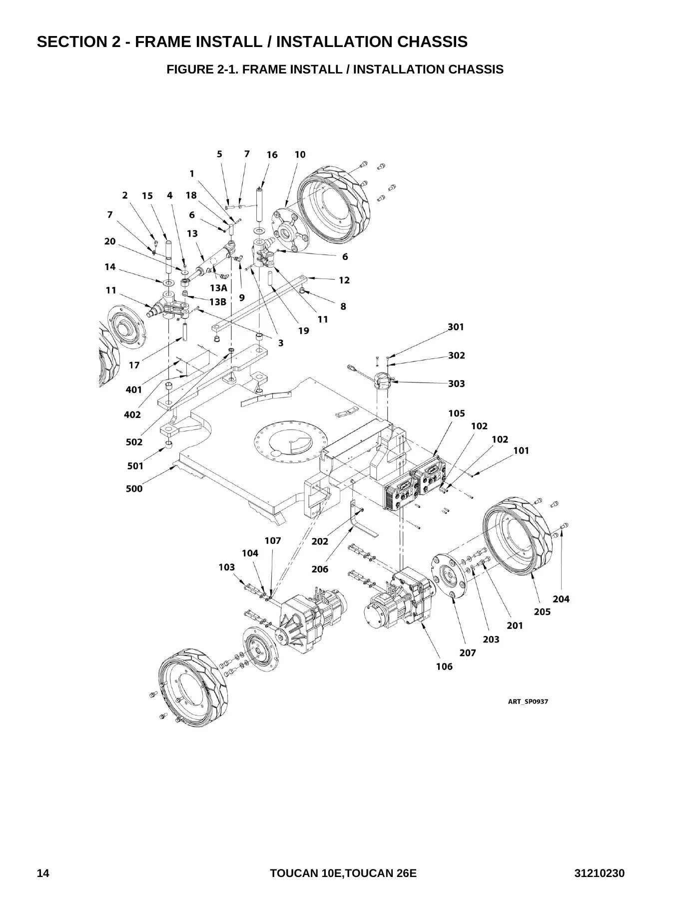
- Section 2 — Frame Install: steering, steering wheel hub, wheel drive, KTY drive gear motor, PT1000 drive gear motor, tires and wheels, tilt switch, serial number tags
- Section 3 — Mast 1 Install: swing drive, turntable bearing, counterweights (920 kg and 1060 kg), additional counterweights, MTB install, ground control panel with enable, ground control panel without enable
- Section 4 — Mast and Boom Install: mast 2 through mast 5, boom lower and upper, roller assembly, pulley assembly, chain anchor, mast cylinder, boom cylinder, pulley support LL10-44, pulley support LL12-66
- Section 5 — Platform Install: platform support, platform drop bar, 26E saloon gates, console and container install, platform console assembly, top rail upper controls protection
- Section 6 — Power Tracks and Clamps Install: power track 27 links, power track 44 links, rotary power track, clamps and mounting hardware
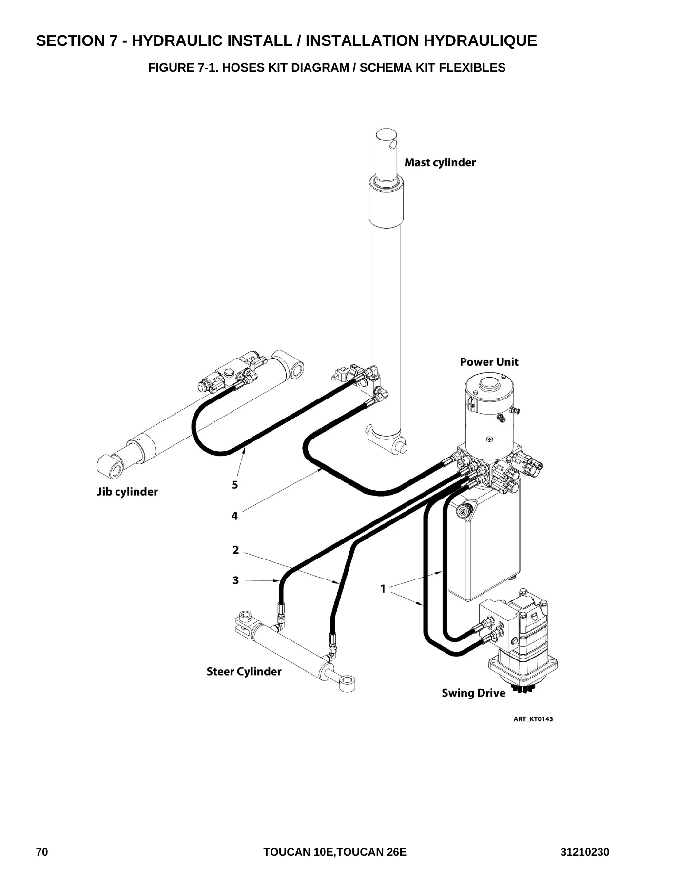
- Section 7 — Hydraulic Install: hoses kit diagram, control valves, tank and pump, pump-motor-tank assembly, valve assembly mast cylinder, valve assembly jib cylinder
- Section 8 — Electrical System Install: cables and switches diagram, power cables kit, battery and charger, switches and covers
- Section 9 — Decals Install: all-products decals, EAC (Russia, CIS) decals
- Section 10 — Options: motion alarm, airline 5/16″, working light, 230V platform socket, 115V IEC platform socket, 115V GFI-US socket, platform obstacle detection, UCB protection, Skyline, Skyline beacon
- Section 11 — Recommended Parts List
- Part Number Index
The manual’s structure follows the machine’s assemblies from the ground up. Each section opens with a full-page exploded illustration with every component numbered, followed by a table listing the item number, part number, quantity, description and revision where applicable. Hardware is itemised down to individual screws, washers, nuts and clamps, so you can order the exact fastener rather than a whole assembly. Two drive gear motor variants appear — the KTY unit used on earlier machines and the PT1000 unit fitted from serial A300040174 (10E) and A300058030 (26E) onward — and the manual separates them clearly so you don’t order the wrong one.
What This Manual Covers In Detail
The hydraulic section maps the complete hose kit with a schematic showing the mast cylinder, jib cylinder, steer cylinder, power unit and swing drive, then breaks each hose down by part number, length and fitting type. Control valve assemblies are shown in exploded view with individual solenoids, coils, flow regulators and seal rings. The electrical section covers the full cable and switch installation diagram with connector types and harness part numbers, plus the battery and charger installation with the AGM battery part number. Decal sections let you replace worn or missing safety and information decals with the correct part number for your market — ANSI, CE, AS/NZL, EAC and others are covered. The options section documents factory and dealer-fit accessories including the motion alarm, working light, platform sockets and Skyline system, each with its own parts list.
Who This Parts Manual Is For
This JLG Toucan 10E & 26E Illustrated Parts Manual is written for the people who keep these machines running: service technicians identifying a failed component, parts managers building stock orders, rental fleet mechanics repairing machines between hires, and owners who want to order the right part without paying dealer markup on every item. Because the illustrations show how assemblies fit together, it also helps when you need to confirm a part is correct before ordering, or when you’re working on a machine built at a different point in the serial range.
Order the Correct Parts Every Time
IMAGES PREVIEW
With this JLG Toucan 10E & 26E Illustrated Parts Manual, you can identify and order replacement parts for the covers, frame, steering, drive motors, wheels, mast, boom, platform, power tracks, hydraulics, electrical system, decals and factory options — all from one document. Correct part numbers mean fewer wrong orders, less downtime and faster repairs. The PDF is available for instant download after purchase, with no shipping and no waiting. Print the pages you need for the workshop, or keep the file on a phone or tablet and search by section while you’re working on the machine.
Reviews
There are no reviews yet.