
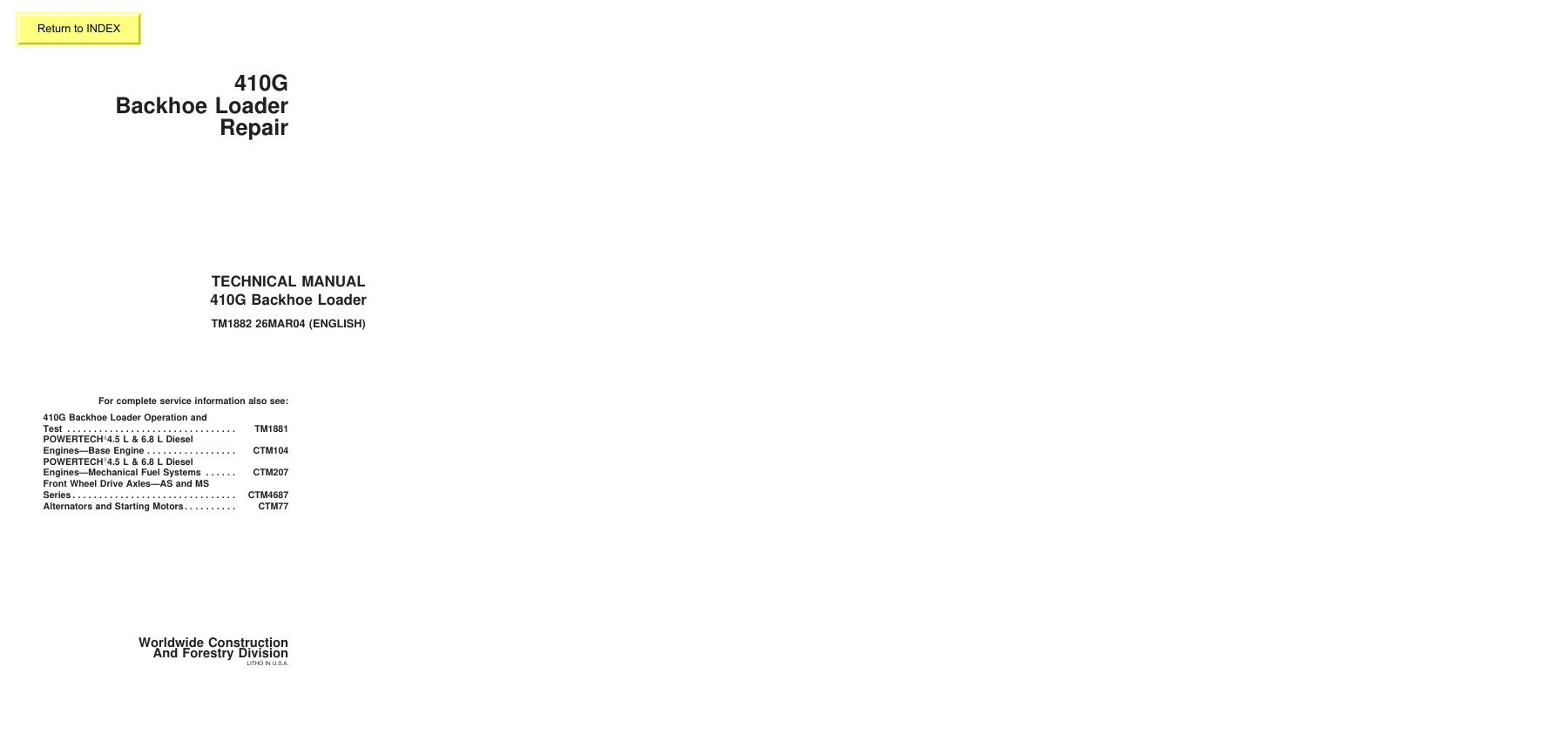
John Deere 410G Backhoe Loader Repair Technical Manual TM1882 – PDF Download
Original price was: $79.95.$49.95Current price is: $49.95.
Complete John Deere 410G Backhoe Loader Repair Technical Manual TM1882. This 878-page PDF covers engine, transmission, axles, hydraulics, electrical, loader, backhoe and more. Instant download.
Description
John Deere 410G Backhoe Loader Repair Technical Manual TM1882
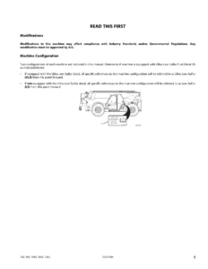
This is the complete John Deere 410G Backhoe Loader Repair Technical Manual TM1882, the same technical manual used by experienced technicians to service, diagnose and repair the 410G backhoe loader. Published March 26, 2004 and written in English, this 878-page PDF is organized by component groups and covers every major system on the machine — from the POWERTECH 4.5L (4045) and 6.8L (6068) diesel engines through the transmission, axles, hydraulics, electrical system, loader and backhoe. Whether you are rebuilding a rear axle, troubleshooting a no-start condition, adjusting the bucket self-leveling linkage or repairing a hydraulic pump, the procedures, specifications and torque values you need are in this manual.
File Details
- Manual Type: Repair Technical Manual
- Brand: John Deere
- Model: 410G Backhoe Loader
- Language: English
- Page Count: 878 pages
- File Format: PDF
- Document Number: TM1882
- Publication Date: 26MAR04 (March 26, 2004)
Chapters Covered
- Section 00 — General Information
- Section 01 — Wheels
- Section 02 — Axles and Suspension Systems
- Section 03 — Transmission
- Section 04 — Engine
- Section 05 — Engine Auxiliary Systems
- Section 06 — Torque Converter
- Section 09 — Steering System
- Section 10 — Service Brakes
- Section 11 — Park Brake
- Section 16 — Electrical System
- Section 17 — Frames, Chassis or Supporting Structure
- Section 18 — Operator’s Station
- Section 19 — Sheet Metal and Styling
- Section 20 — Safety, Convenience and Miscellaneous
- Section 21 — Main Hydraulic System
- Section 31 — Loader
- Section 33 — Backhoe
- Section 99 — Dealer Fabricated Tool
Section 00 — General Information
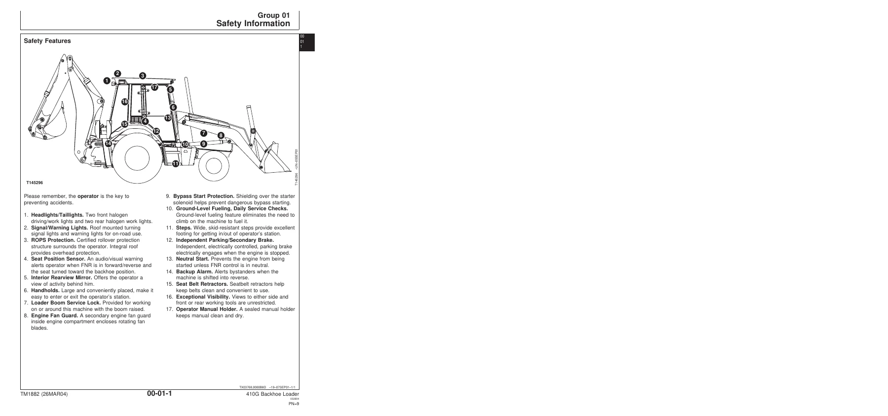
Safety information covering all aspects of machine operation and service: safety features, protective equipment, high-pressure fluid hazards, fire prevention, battery safety, chemical handling, safe parking and service procedures. Also includes safety sign locations and the technical information feedback form.
Section 01 — Wheels
Remove and install procedures for rear and front wheel assemblies, including torque specifications for wheel cap screws and lug nuts. Also covers tire removal and installation, including safe inflation procedures and tire pressure specifications. Rear wheel weights are listed for both fluid-filled and non-fluid configurations.
Section 02 — Axles and Suspension Systems
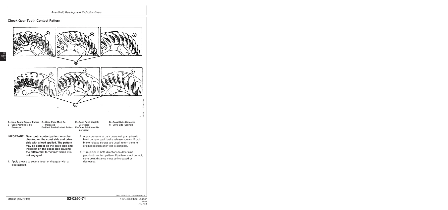
Covers drive shafts and U-joints (remove, install, replace), non-powered front axle hub assembly, spindle and knuckle assembly, tie rod, front axle removal and installation for both early and later serial numbers. The rear axle group includes removal and installation, disassembly and assembly, service brake inspection, park brake disassembly and assembly for both serial number ranges, differential and pinion setup, shim pack determination, gear tooth contact pattern checking, and complete torque specifications.
Section 03 — Transmission
Removal and installation of the PowerShift transmission, controls linkage (FNR control), input drive shafts and U-joints, gears, shafts, bearings and PowerShift clutches. Includes clutch pack disassembly and assembly for low range forward, reverse, third speed, first speed, second speed and high range forward. Also covers the hydraulic system: charge pump, control valve, shift valve, manifold plate and solenoids. Complete specifications and torque values are provided throughout.
Section 04 — Engine
Engine removal and installation for the POWERTECH 4.5L (4045) and 6.8L (6068) John Deere diesel engines. Covers all steps for safely removing and reinstalling the engine, including disconnecting and reconnecting all associated systems. References CTM104 for base engine repair and CTM207 for mechanical fuel systems.
Section 05 — Engine Auxiliary Systems
Cold weather starting aid (coolant heater, starting aid nozzle, starting aid solenoid), cooling system (fan, fan belt, radiator), speed controls (speed control linkage), intake system (air cleaner, air intake leak test), exhaust system (muffler with turbocharger), and external fuel supply system (fuel tank removal and installation).
Section 06 — Torque Converter
Torque converter removal and installation and disassembly and assembly procedures. The torque converter has no internal service parts — if replacement is necessary, a new torque converter is installed.
Section 09 — Steering System
Steering cylinder repair for front wheel drive axles (references CTM4687 for AS and MS Series axles), steering column removal and installation, standard and tilt steering wheel and column disassembly and assembly, steering valve removal and installation for both serial number ranges, steering valve disassembly and assembly, cross-section diagrams, non-powered axle steering cylinder removal, disassembly, assembly and repair, steering cylinder bushing removal and installation, and MFWD axle steering cylinder cross-section and repair procedures.
Section 10 — Service Brakes
Service brake external inspection, brake disk and pressure plate removal and installation, brake valve removal and installation, brake valve disassembly and assembly, brake valve lines disassembly and assembly, brake pedal removal and installation, brake pedal adjustment, and bleeding procedures. Includes torque specifications and pedal travel dimensions.
Section 11 — Park Brake
Park brake removal and installation. The park brake is part of the rear axle; removal and installation reference the rear axle procedure in Group 0250.
Section 16 — Electrical System
Batteries, support and cables (service procedures, testing, electrolyte level, charging, booster batteries, removal and installation), alternator and charging system wiring (specifications, removal and installation), wiring harness and switches (component location for all harnesses, fuse specifications, connector replacement for Kostal, DEUTSCH and WEATHER PACK connectors), instruments and indicators (fuel gauge sender removal and installation), and motors and actuators (starter motor removal and installation, starter relay removal and installation).
Section 17 — Frames, Chassis or Supporting Structure
Frame installation (welding repair of major structures, RIVNUT/KREMNUT fastener removal and installation, main frame bushing removal and installation) and chassis weights (counterweight removal and installation with torque specifications).
Section 18 — Operator’s Station
Cab/ROPS removal and installation, operator enclosure (front and rear window wiper and motor, fixed windowpanes, cab door and side window disassembly and assembly, door latch and hinge adjustment, rear windows, headliner, cab roof), seat and seat belt (seat assembly removal and installation, seat/belt/arm rest disassembly and assembly, seat slide/swivel/lumbar control levers, seat swivel and latch, seat suspension and shock absorber, seat base and support, air seat suspension), and heating and air conditioning (R134a refrigerant handling, compressor, clutch, evaporator, condenser, receiver dryer, heater core, blower, air ducts, A/C freeze switch, flushing, purging, evacuation, charging and leak testing).
Section 19 — Sheet Metal and Styling
Hood and engine enclosure disassembly and assembly, battery box disassembly and assembly, grille and grille housing disassembly and assembly, and fenders and cab skirt removal and installation.
Section 20 — Safety, Convenience and Miscellaneous
Radio and speakers removal and installation, antenna removal and installation, horn removal and installation, back-up alarm removal and installation, and back-up alarm volume adjustment.
Section 21 — Main Hydraulic System
Hydraulic pump removal and installation for both serial number ranges, pump cross-section, control piston and load sense module, flow limiter, complete pump disassembly, inspection and assembly, hydraulic filter removal and installation, reservoir removal and installation and disassembly and assembly, and hydraulic and transmission oil cooler removal and installation. Includes complete specifications and torque values for all hydraulic components.
Section 31 — Loader
Loader removal and installation, bucket removal and installation, welded cutting edge replacement, cracked cutting edge repair, cutting edge removal and installation, multi-purpose bucket and lines disassembly and assembly, loader control valve linkage removal and installation (two-spool and three-spool), loader bucket self-leveling linkage and return-to-dig switch adjustment, loader control valve removal and installation, disassembly and assembly, relief valve repair, wiper rings and seals replacement, loader boom and bucket cylinder removal and installation, disassembly and assembly, ride control valve removal, installation, disassembly and assembly, ride control valve solenoid removal and installation, ride control accumulator removal and installation, charging and discharge procedures.
Section 33 — Backhoe
Backhoe bucket and bucket links removal and installation, bucket tooth shanks and tips removal and installation, bucket cutting edge removal and installation, backhoe boom swing lock control lever and linkage removal and installation, backhoe boom lock arms and locking pin removal and installation, pilot control valve repair, pilot control tower repair, backhoe valve linkage removal and installation (two-lever and three-lever), fifth and sixth function pedal removal and installation, stabilizer valve linkage removal and installation, backhoe control valve removal and installation, disassembly and assembly, backhoe circuit relief and system relief valve removal and installation, anti-cavitation valve disassembly and assembly, backhoe valve sections disassembly and assembly (inlet, auxiliary flow, swing, boom, bucket, crowd, extendible), wiper rings and seals replacement, pilot control manifold valve repair, pattern select valve repair, stabilizer valve removal, installation, disassembly and assembly, backhoe cylinder removal and installation (bucket, crowd, boom, extendible dipperstick, swing, stabilizer), and cylinder disassembly and assembly procedures for 125 Series, 120 Series and extendible dipperstick cylinders.
Section 99 — Dealer Fabricated Tool
Drawings and material specifications for dealer-fabricated tools including DFT1146 Axle Mounting Bracket, DFT1147 Axle Rolling Torque Bar, DFT1162 Powershift Clutch Pack Snap Ring Removal and Installation Tool, DFT1163 MFWD Snap Ring Removal and Installation Tool, DFRW20 Compressor Holding Fixture, DFT1101 Cab and ROPS Lift Bracket, and DFT1143 Transmission Support Bracket.
Why This Manual Matters
The John Deere 410G Backhoe Loader is a complex machine with interconnected hydraulic, electrical, powertrain and structural systems. Working on it without the correct procedures, torque values and specifications is risky — both to the machine and to the technician. This TM1882 Repair Technical Manual gives you the same information John Deere technicians use: step-by-step disassembly and assembly sequences, complete torque tables, wear tolerances, shim pack determination methods, gear tooth contact pattern checks, hydraulic system specifications and electrical component locations. When you need to set up a rear axle, adjust a return-to-dig switch, repair a hydraulic pump, replace a clutch pack, or diagnose an electrical fault, this manual provides the correct procedure rather than a guess.
Additional Service Information
For complete service information on the 410G Backhoe Loader, this manual should be used alongside the Operation and Test Manual TM1881. For engine repair beyond removal and installation, the manual references POWERTECH 4.5L (4045) and 6.8L (6068) Diesel Engines Base Engine CTM104 and POWERTECH 4.5L (4045) and 6.8L (6068) Diesel Engines Mechanical Fuel Systems CTM207. For front wheel drive axle repair, see Front Wheel Drive Axles — AS and MS Series CTM4687. For alternator and starting motor repair, see CTM77.
IMAGES PREVIEW
Instant PDF Delivery — No Shipping, No Waiting
This John Deere 410G Backhoe Loader Repair Technical Manual TM1882 is delivered as an instant PDF download immediately after payment. There is no physical book to ship, no waiting for delivery and no shipping cost. The PDF can be viewed on any device — laptop, desktop, tablet or smartphone — and relevant pages can be printed for use in the workshop. Whether you are a professional technician, a dealer workshop, a fleet maintenance manager or an owner-operator who does their own repairs, having this manual on hand means you can tackle jobs with the correct procedures and specifications from the start. The 878-page PDF covers the complete machine, making it a comprehensive reference for the 410G Backhoe Loader.
Reviews
There are no reviews yet.