
John Deere 540G, 640G, 740G Skidder and 548G, 648G, 748G Grapple Skidder Technical Repair Manual TM1600 PDF
Original price was: $39.95.$23.95Current price is: $23.95.
John Deere Technical Repair Manual TM1600 for the 540G, 640G, 740G cable skidders and 548G, 648G, 748G grapple skidders through serial number 565684 – component removal, disassembly, assembly, installation, torque values, capacities and dealer fabricated tools in one PDF.
Description
John Deere 540G, 640G, 740G Skidder and 548G, 648G, 748G Grapple Skidder Technical Repair Manual – TM1600
The John Deere Technical Repair Manual TM1600 covers the G-Series skidder line through serial number 565684 – the 540G, 640G and 740G cable skidders together with the 548G, 648G and 748G grapple skidders. Written by John Deere for the experienced technician and dated 03AUG98, this repair manual takes every component group from removal and disassembly through inspection, assembly and installation, and opens each group with the essential tools, service parts kits, wear tolerances and torque values needed before any work starts.
If you are searching for the factory-level John Deere 540G, 640G, 740G Skidder and 548G, 648G, 748G Grapple Skidder Technical Repair Manual TM1600, this is the document itself – not a summary, not a generic skidder book, and not a collection of third-party notes. It is the repair half of the John Deere service documentation set for these machines, laid out section by section in the same numbering system John Deere technicians use in the shop.
File Details
- Manual type: Technical Repair Manual (component repair)
- Document number: TM1600
- Publication date: 03AUG98
- Language: English
- Brand: John Deere
- Models covered: 540G, 640G, 740G Skidder and 548G, 648G, 748G Grapple Skidder
- Serial number coverage: (S.N. -565684)
- File format: PDF
- Scope: Over 1,000 pages, paginated by section
Chapters Covered
- Section 00 – General Information: Safety Information; General Specifications; Torque Values; Fuels and Lubricants
- Section 01 – Wheels: Powered Wheels and Fastenings
- Section 02 – Axles and Suspension System: Removal and Installation; Input Drive Shafts and U-Joints; Hydraulic System
- Section 03 – Transmission: Removal and Installation; Control Linkage; Input Drive Shafts and U-Joints; Gears, Shafts and Bearings; Hydraulic System
- Section 04 – Engine: Removal and Installation
- Section 05 – Engine Auxiliary Systems: Cold Weather Starting Aids; Cooling Systems; Speed Controls; Intake System; External Exhaust System; External Fuel Supply System
- Section 07 – Damper Drive: Elements
- Section 09 – Steering System: Secondary Steering; Hydraulic System
- Section 10 – Service Brakes: Active Elements; Controls Linkage; Hydraulic System
- Section 11 – Park Brake: Active Elements; Hydraulic System
- Section 16 – Electrical System: Batteries, Support and Cables; Alternator, Regulator and Charging System Wiring; Lighting System; Wiring Harness and Switches; Instruments and Indicators; Motors and Actuators
- Section 17 – Frame, Chassis or Supporting Structures: Frame Installation; Frame Bottom Guards
- Section 18 – Operator’s Station: Removal and Installation; Operator Enclosure; Seat and Seat Belt; Heating and Air Conditioning
- Section 19 – Sheet Metal and Styling: Hood or Engine Enclosure; Grille and Grille Housing
- Section 20 – Safety, Convenience and Miscellaneous: Fire Extinguisher; Horn and Warning Devices
- Section 21 – Main Hydraulic System: Hydraulic System
- Section 30 – Winch: Removal and Installation; Controls Linkage; Input Drive Shafts and U-Joints
- Section 32 – Bulldozers: Stacking and Trailbuilding Blades
- Section 37 – Arch or Boom: Frames
- Section 38 – Grapple: Grapple Mechanism; Control Linkage; Frames; Hydraulic System
- Section 99 – Dealer Fabricated Tools
Read as a whole, TM1600 is a disassembly-to-reassembly guide rather than a theory book. It assumes you already know how a powershift transmission or a load-sensing steering circuit works and gets straight to the practical questions: how the axle and differential come out of the frame, how the front and rear oscillating supports are shimmed, how the transmission control valve and clutch packs come apart, how the oil manifold and C1 and C2 clutch pack assembly are assembled, how the planetary pack is set up, how the park brake is removed and reinstalled, how the grapple rotate motor and rotary manifold come apart, and what the correct end play, torque or capacity is at each step. Where a job needs a special tool, the tool is named and, in Section 99, the dealer fabricated tools such as the yoke holding tool, bushing drivers, transmission floor stand, gear alignment tool and lift handle are covered so they can be made rather than bought.
Engines, Axles and Winches Covered in This Manual
The engine sections in TM1600 cover removal and installation plus the auxiliary systems around the engine, and the manual is split by serial number because John Deere changed engine families partway through G-Series production. Early machines (S.N. -558324 for the 540G, 548G, 640G and 648G, and S.N. -559114 for the 740G and 748G) are documented with the John Deere 6059T, 6068T and 6076T turbocharged engines. Later machines move to the PowerTech range, with the PowerTech 6068T and PowerTech 6081T engines covered separately. Fuel system work is split the same way, with distinct removal, installation, timing and bleeding procedures for the DB4 fuel injection pump, the injection pump on later serial numbers, and the fuel injection nozzles – plus the JT07158 Time Trac installation procedure.
Axle coverage follows the machine: the 1200 Series TeamMate II front and rear axles on the lighter skidders, the 1400 Series TeamMate II axles on the heavier 740G, 748G and the rear of the 648G. Differential lock solenoid valve and relief valve service, differential plumbing, front and rear differential drive shafts and the universal joint installation and lubrication procedure are all included, along with the oscillating support shimming procedure that sets axle-to-frame end play. Winch coverage spans both the 4000 Series and 6000 Series winches, including removal, installation, drum plug fitting, fastening cable to the drum and free spool drag adjustment.
One point worth stating plainly: for complete overhaul of certain components, TM1600 points to the matching John Deere component technical manuals. Axle repair directs you to CTM43 (1200 and 1400 Series TeamMate II axles), winch repair to CTM25 (4000 Series) and CTM41 (6000 Series), and engine work to CTM8, CTM42, CTM86 and CTM104 depending on the engine. TM1600 itself carries the machine-level removal, installation and system repair procedures and the specifications that go with them.
What This John Deere G-Series Skidder Repair Manual Lets You Do
With TM1600 open on the bench you can pull and reinstall a front or rear axle and differential, rebuild the oscillating supports and set the end play to spec, drop the transmission or repair it in frame, work through the transmission control valve, clutch valves, pressure regulating valve, accumulators and shift valves, service the park brake and its sensor valve, diagnose and repair the steering system including the secondary steering pump and priority valve, rebuild the service brake valve and bleed the brakes, and repair the main hydraulic pump, reservoir and filtration system. On the electrical side the manual covers batteries and cables, the alternator and charging wiring, lighting, harnesses and switches, instruments and indicators, and starting motors. Cab and canopy removal, isolators, windows, doors, wiper and washer, the suspension seat and seat belts, and the heating and air conditioning system including R134a recovery, evacuation, charging and leak testing are all documented, as are the hood, grille and grille housing and the frame pivot pins and bottom guards.
That matters because these machines are worked hard in the woods, and guessing at a torque value, an end play figure or a tightening sequence is how a differential lock starts leaking, a pivot pin works loose, or a freshly assembled clutch pack fails early. Having the John Deere 540G, 640G, 740G and 548G, 648G, 748G Grapple Skidder Technical Repair Manual TM1600 on hand means the specification you need is the specification John Deere published for your serial number range, not a number someone remembered from a different machine.
Delivery is instant. The moment payment clears you get the PDF, no shipping, no waiting on a parcel, no bulky binder on the shelf. Open it on a laptop or tablet in the shop, print the pages for the job in front of you and take them under the machine, and keep the file for every future service on your 540G, 640G, 740G, 548G, 648G or 748G.
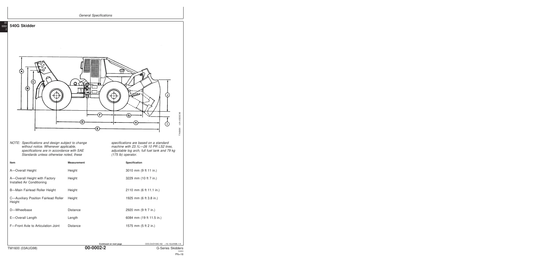
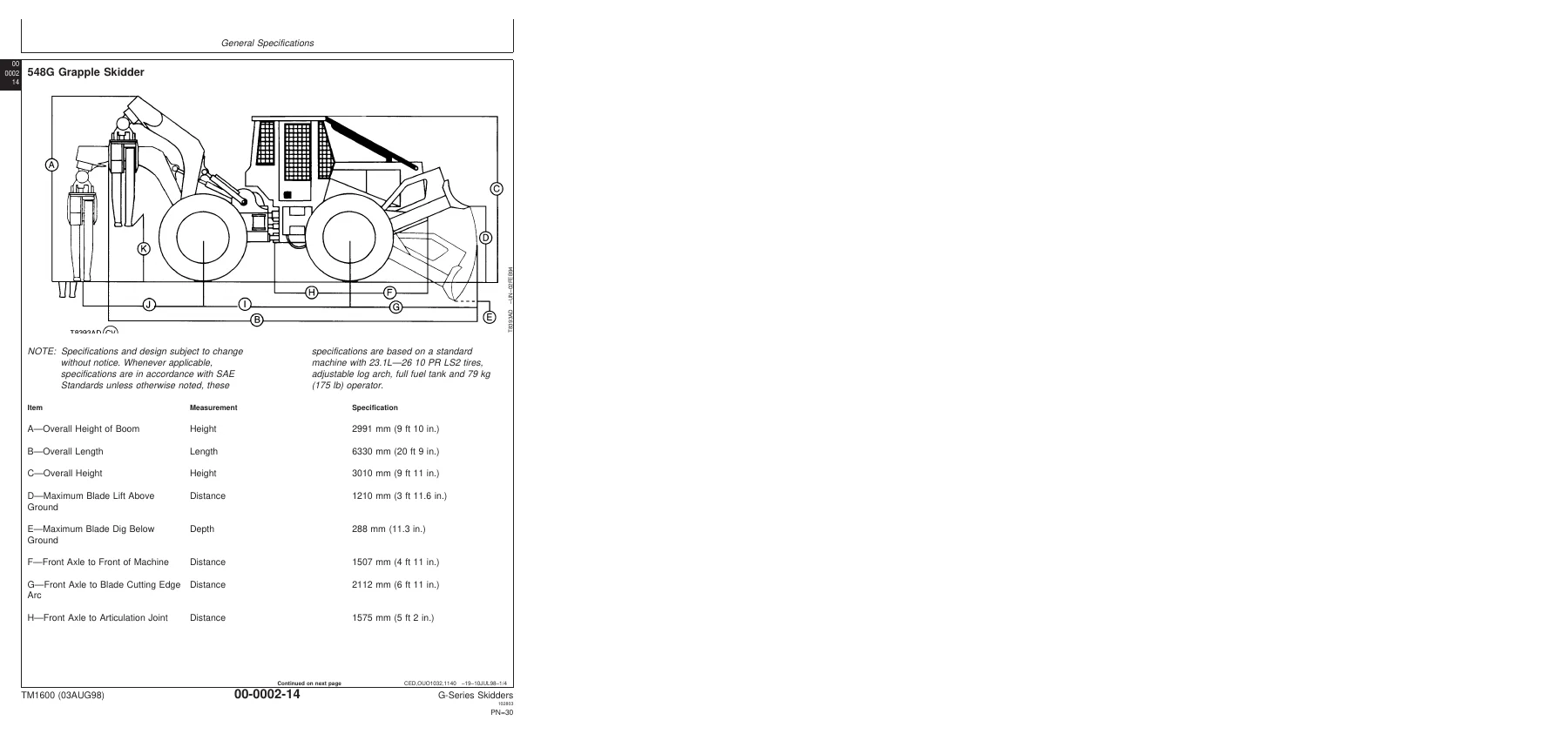
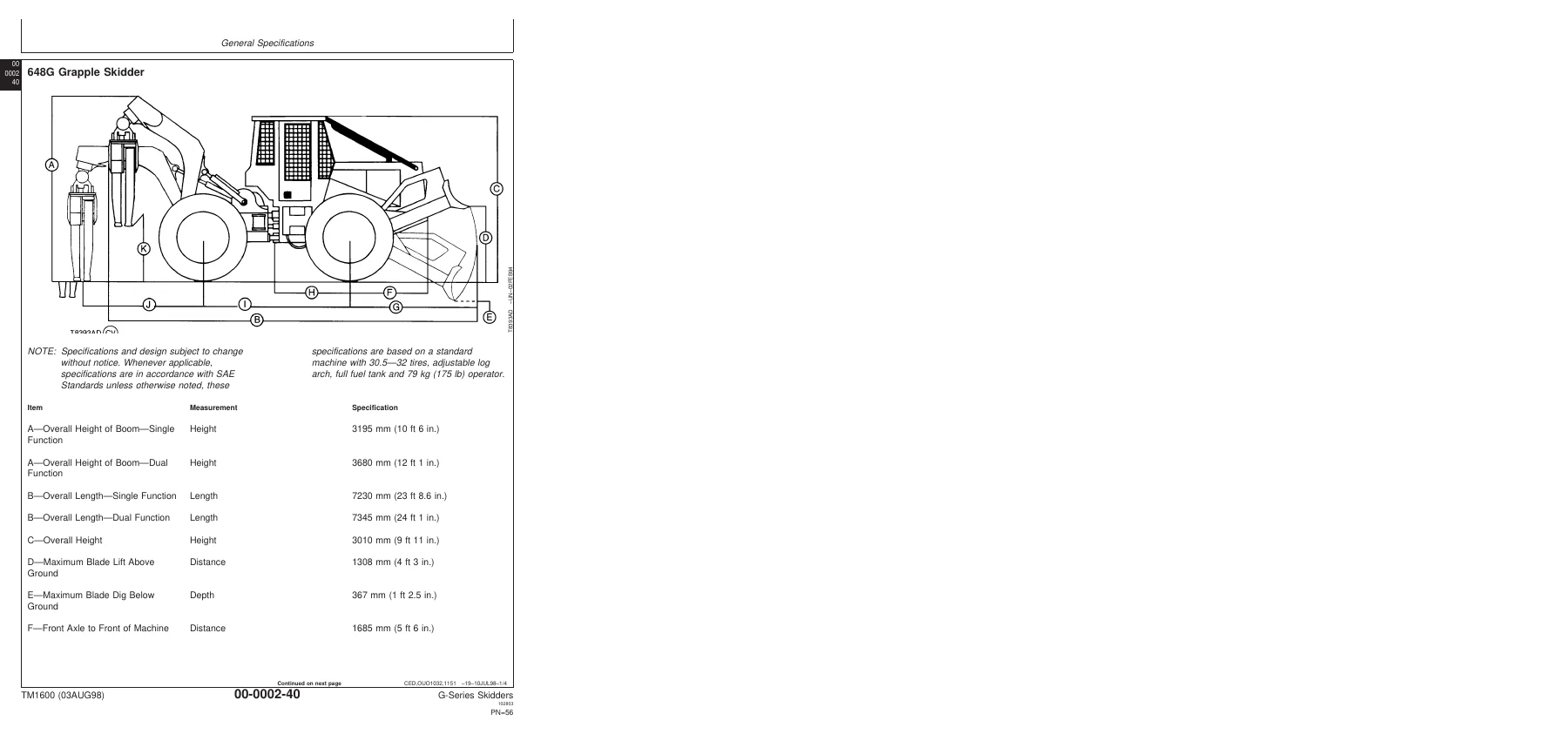
IMAGES PREVIEW

Reviews
There are no reviews yet.