★ TRUSTED BY 321,897+ PROFESSIONALS WORLDWIDE
🏒
Trusted Business
Verified & Licensed
πŸ›‘οΈ
Virus Free Files
100% Safe Downloads
πŸ”’
Secure Payment
SSL Protected
⚑
Instant Delivery
Available Immediately
Sale!

John Deere 544G 624G 644G 4WD Loaders Repair Technical Manual – TM1530 (2005) PDF

Original price was: $44.95.Current price is: $26.95.

Complete John Deere 544G 624G 644G 4WD Loaders Repair Technical Manual (TM1530, 22 FEB 05) covering engine, transmission, hydraulics, brakes, steering, electrical, cab and loader linkage repair with torque specs, capacities, disassembly/assembly steps and dealer-fabricated tool drawings.

⚑
Instant PDF Download
Available immediately
πŸ’Ύ
Save to Your Device
Download & keep forever
πŸ›‘οΈ
Antivirus Scanned
100% virus-free
🌍
Trusted Worldwide
175,000+ customers

Description

John Deere 544G 624G 644G 4WD Loaders Repair Technical Manual – TM1530 (2005)

This is the complete John Deere 544G 624G 644G 4WD Loaders Repair Technical Manual TM1530, dated 22 FEB 05, covering the 544G, 544G LL, 544G TC, 624G, and 644G wheel loaders. If you work on any of these machines, this John Deere 544G 624G 644G repair manual is the shop-level reference the manufacturer’s own technicians use for removal, disassembly, inspection, assembly, installation, and torque specifications across every major system on the loader.

File Details

  • Manual type: Repair Technical Manual (workshop/service repair manual)
  • Document number: TM1530
  • Date: 22 FEB 05
  • Brand / Models: John Deere 544G, 544G LL, 544G TC, 624G, 644G 4WD Loaders
  • Language: English
  • File format: PDF, instant digital download

IMAGES PREVIEW

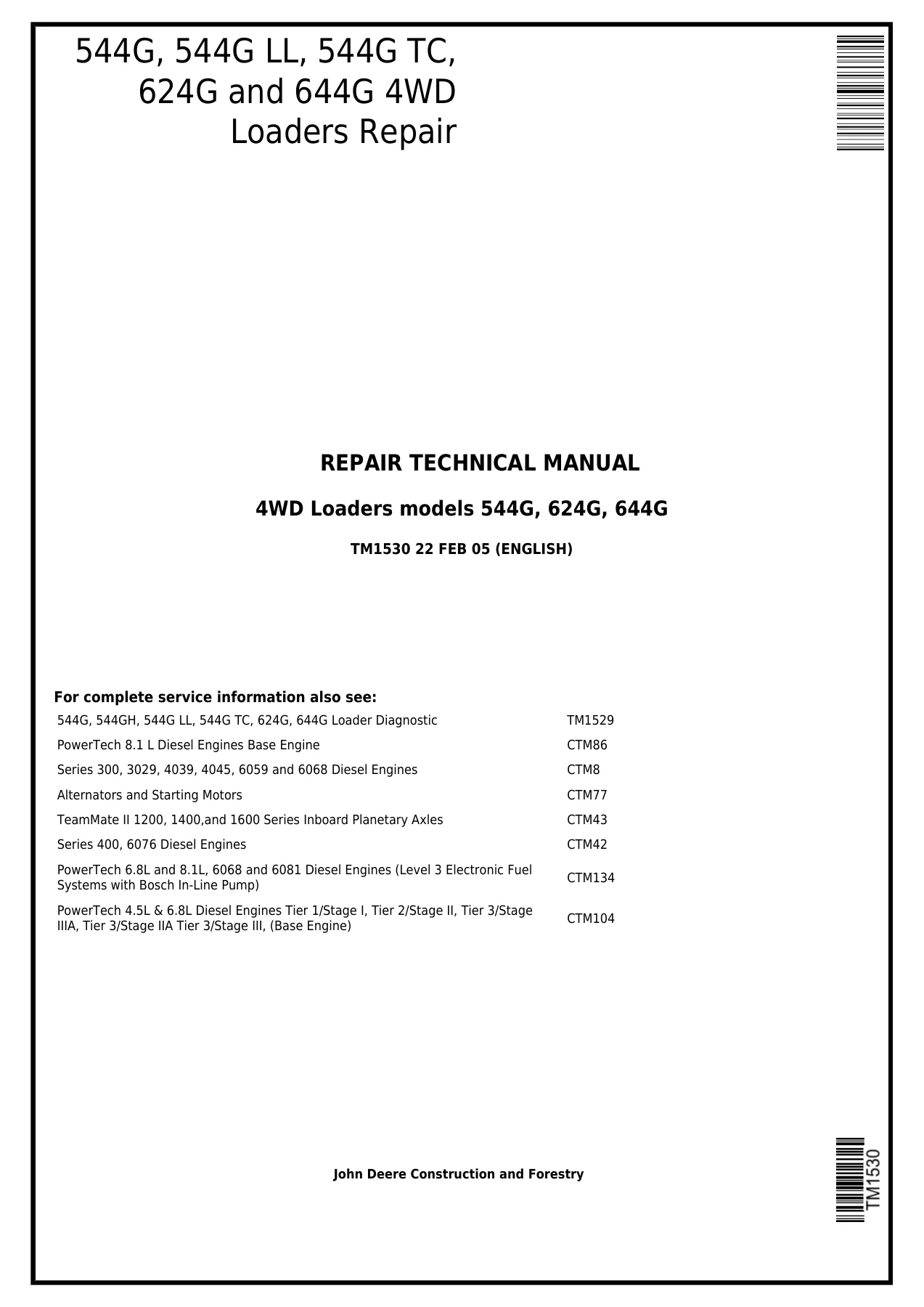
John Deere 544G 624G 644G 4WD Loaders Repair Technical Manual - TM1530 (2005) PDF β€” PDF page 1 preview
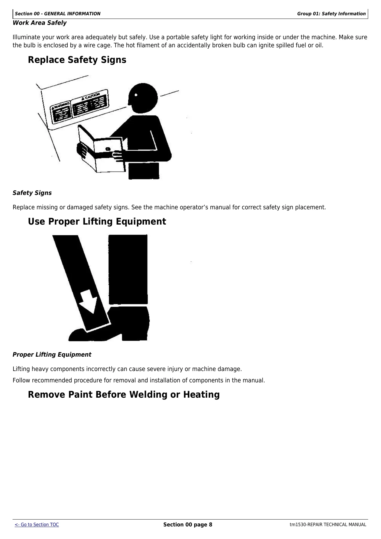
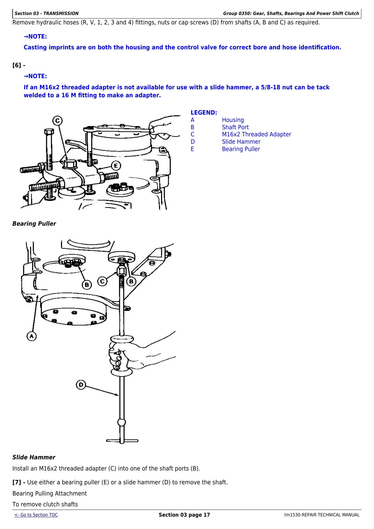
John Deere 544G 624G 644G 4WD Loaders Repair Technical Manual - TM1530 (2005) PDF β€” PDF page 16 preview
John Deere 544G 624G 644G 4WD Loaders Repair Technical Manual - TM1530 (2005) PDF β€” PDF page 100 preview

Chapters Covered

  • Section 00 – General Information: Safety Information, General Specifications (all five models), Torque Values, Fuels and Lubricants, Inspection Procedures / PIP I and PIP II checklists
  • Section 01 – Wheels: Powered Wheels and Fastenings, tire removal/installation by model
  • Section 02 – Axles and Suspension Systems: front/rear axle and differential removal and installation, axle shafts, bearings, U-joints, differential lock hydraulics
  • Section 03 – Transmission: transmission removal/installation, control linkage, input drive shafts, gears/shafts/power shift clutch packs, hydraulic oil supply system, control valve, thermal bypass valve
  • Section 04 – Engine: engine removal/installation, oil pan, fuel injection pump (544G/624G and 644G procedures separately), turbocharger, water pump, fan drive
  • Section 05 – Engine Auxiliary Systems: cold weather starting aids, cooling system, speed controls, intake system, external fuel supply system
  • Section 07 – Dampener Drive
  • Section 09 – Steering System: secondary steering, steering valve, steering column, steering cylinders, priority valve
  • Section 10 – Service Brakes: brake pads, brake assembly, brake valve, brake pump, brake accumulator, bleeding procedure
  • Section 11 – Park Brake: pads, adjustment, release solenoid valve, pressure switch
  • Section 15 – Equipment Attaching: drawbar/counterweight installation
  • Section 16 – Electrical Systems: batteries, alternator, lighting, wiring harness/switches, starting motor
  • Section 17 – Frame or Supporting Structure: frame separation, upper/lower pivot bearings, bottom guards, chassis weights
  • Section 18 – Operator’s Station: cab/canopy, windows, wipers, seat and seat belt, heating and air conditioning (R12 and R134a service)
  • Section 31 – Loader: bucket, frames/bucket linkage, main hydraulic pump, loader control valve, boom/bucket cylinders, hydraulic reservoir, pilot control valves (two-lever and single-lever), ride control
  • Section 99 – Dealer Fabricated Tools with build drawings and dimensions

Together these sections give a technician the full repair path for a John Deere 544G 624G 644G loader – from a stuck tire and a worn brake disk up to a complete transmission clutch pack rebuild, torque converter service, or steering valve overhaul – with the correct sequence, tooling, and torque value called out at every step.

Complete PDF Bookmark Tree

Complete Bookmarks

The complete bookmarks in the β€œJohn Deere 544G 624G 644G 4WD Loaders Repair Technical Manual – TM1530 (2005) PDF” are as follows:

Table of contentsp. 2
FOREWORDp. 5
HELP!! HELP!! HELP!! HELP!!p. 6
Section 00 – GENERAL INFORMATIONp. 9
Group 01 – Safety Informationp. 9
Handle Fluids Safely-Avoid Firesp. 9
Prevent Battery Explosionsp. 9
Prepare for Emergenciesp. 9
Prevent Acid Burnsp. 11
Handle Chemical Products Safelyp. 11
Avoid High-Pressure Fluidsp. 12
Park Machine Safelyp. 12
Support Machine Properlyp. 13
Wear Protective Clothingp. 14
Work in Clean Areap. 14
Service Machines Safelyp. 14
Work In Ventilated Areap. 15
Illuminate Work Area Safelyp. 15
Replace Safety Signsp. 16
Use Proper Lifting Equipmentp. 16
Remove Paint Before Welding or Heatingp. 16
Avoid Heating Near Pressurized Fluid Linesp. 18
Keep ROPS Installed Properlyp. 18
Service Tires Safelyp. 19
Avoid Harmful Asbestos Dustp. 19
Practice Safe Maintenancep. 21
Use Proper Toolsp. 21
Dispose of Waste Properlyp. 22
Live With Safetyp. 22
Group 02 – General Specificationsp. 24
544G Specificationsp. 24
544G Drain And Refill Capacitiesp. 26
544G LL Specificationsp. 27
544G LL Drain And Refill Capacitiesp. 29
544G TC Specificationsp. 30
544G TC Drain And Refill Capacitiesp. 32
624G Specificationsp. 33
624G Drain And Refill Capacitiesp. 35
644G Specificationsp. 36
644G Drain And Refill Capacitiesp. 38
Group 0003 – Torque Valuesp. 39
Hardware Torque Specificationsp. 39
ROPS Torque Specificationsp. 39
Metric Bolt and Cap Screw Torque Valuesp. 40
Additional Metric Cap Screw Torque Valuesp. 41
Unified Inch Bolt and Cap Screw Torque Valuesp. 43
Check Oil Lines And Fittingsp. 43
Service Recommendations for O-Ring Boss Fittingsp. 45
Service Recommendations for Flat Face O-Ring Seal Fittingsp. 47
Service Recommendations for Metric Series Four Bolt Flange Fittingp. 48
Service Recommendations For Inch Series Four Bolt Flange Fittingsp. 49
Group 0004 – Fuels And Lubricantsp. 50
Fuel Specificationsp. 50
Storing Fuelp. 50
Do Not Use Galvanized Containersp. 50
Fuel Tankp. 50
Engine Oilp. 50
Hydraulic System Oil And Differential Oilp. 51
Transmission Oilp. 52
Greasep. 52
Alternative and Synthetic Lubricantsp. 53
Lubricant Storagep. 53
Mixing of Lubricantsp. 53
Diesel Engine Coolantp. 54
Group 0005 – Inspection Proceduresp. 55
Planned Inspection Program I (PIP I)p. 55
Planned Inspection Program II (PIP II)p. 55
Using The Checklistsp. 55
Delivery Servicep. 55
John Deere 544G, 624G And 644G Loaderp. 56
John Deere 544G, 624G, And 644G Loaderp. 58
Section 01 – WHEELSp. 61
Group 0110 – Powered Wheels And Fasteningsp. 61
Other Materialp. 61
Specificationsp. 61
Remove Tirep. 62
Install Tirep. 63
544G And 544G TCp. 65
544G LLp. 66
624Gp. 67
644Gp. 68
Section 02 – AXLES AND SUSPENSION SYSTEMSp. 70
Group 0200 – Removal And Installationp. 70
John Deere 1200 And 1400 Series Axles-Use CTM43p. 70
Other Materialp. 70
Specificationsp. 70
Remove And Install Front Axle And Differentialp. 71
Remove Rear Axle And Differentialp. 73
Install Rear Axle And Differential Assemblyp. 76
Group 0225 – Axle Shafts, Bearings And U-Jointsp. 77
Other Materialp. 77
Specificationsp. 77
Disassemble, Inspect, And Assemble Support Bearing And Drive Shaftp. 78
Remove And Install Rear Differential Drive Linep. 79
Group 0260 – Hydraulic Systemp. 80
Specificationsp. 80
Remove And Install Differential Lock Solenoid Valvep. 80
Section 03 – TRANSMISSIONp. 84
Group 0300 – Removal And Installationp. 84
Essential Toolsp. 84
Service Equipment And Toolsp. 84
Specificationsp. 84
Remove And Install Transmissionp. 85
Group 0315 – Control Linkagep. 90
Other Materialp. 90
Specificationsp. 90
Remove And Install Transmission Shift Leverp. 91
Group 0325 – Input Drive Shafts And U-Jointsp. 92
Specificationsp. 92
Remove, Disassemble, Assemble And Install Transmission Drive Shaftp. 92
Group 0350 – Gear, Shafts, Bearings And Power Shift Clutchp. 93
Essential Toolsp. 93
Service Equipment And Toolsp. 93
Other Materialp. 94
Specificationsp. 94
Install Repair Standp. 95
Remove And Install Torque Converterp. 96
Remove Clutch Packsp. 98
Remove And Install Forward And First Drive Gearsp. 103
Remove And Install Reverse And Second Drive Gearsp. 105
Remove And Install Third And Fourth Drive Gearsp. 107
Disassemble And Assemble Clutch Packsp. 108
Clutch Packsp. 117
Remove And Install Fourth Gear Idler Gear-624G, 644Gp. 117
Fourth Gear Idler Gear Shaft Orifice Sizesp. 120
Install Fourth Gear Idler Gear-544G, 544G LL, 544G TCp. 120
Install Third And Fourth Gear Clutch Pack, Adjust End Playp. 122
Install Second And Reverse, First And Forward Gear Clutch Packsp. 127
Remove And Install Output Flangep. 134
Remove And Install Output Shaft And Sealsp. 136
Remove And Install Output Gear And Oil Shieldsp. 141
Remove And Install Speed Control Magnetic Pickupp. 144
Group 0360 – Hydraulic Systemp. 145
Essential Toolsp. 145
Service Equipment And Toolsp. 145
Other Materialp. 145
Specificationsp. 145
Remove Oil Supply Flange And Oil Pumpp. 147
Disassemble Oil Supply Flangep. 148
Assemble Oil Supply Flangep. 150
Input Drive Shaft Orifice Sizesp. 153
Disassemble Oil Pumpp. 154
Assemble Oil Pumpp. 155
Install Oil Pump On Oil Supply Flangep. 158
Install Oil Supply Flange And Oil Pumpp. 161
Remove And Install Converter Minimum Pressure Regulatorp. 165
Remove And Install Transmission Oil Filterp. 165
Remove And Install Suction Oil Strainerp. 167
Remove Transmission Control Valvep. 167
Repair Transmission Control Valve 544G (SN -542218), 624G (SN -548398), 644G (SN -548302)p. 171
Control Valve W/6th Solenoid-544G (SN 548219-), 624G (SN 548398-), 644G (SN 548303-)p. 174
Install Transmission Control Valvep. 177
Cross Section Of Thermal Bypass Valvep. 179
Disassemble And Assemble Thermal Bypass Valvep. 179
Section 04 – ENGINEp. 182
Group 0400 – Removal And Installationp. 182
John Deere 6059 Engine Repair-Use CTM8p. 182
John Deere 6068 Engine Repair-Use CTM8p. 182
John Deere 6076 Engine Repair-Use CTM42p. 182
John Deere 6081 Engine Repair-Use CTM86p. 182
Special Or Essential Toolsp. 183
Service Equipment And Toolsp. 183
Other Materialp. 184
Specificationsp. 185
Disconnect Turbocharger Oil Inlet Linep. 185
Remove And Install Enginep. 186
Remove And Install Oil Panp. 188
Remove Fuel Injection Pump-544G, 624Gp. 189
Install Fuel Injection Pump-544G, 624Gp. 191
Remove Fuel Injection Pump-644Gp. 192
Install Fuel Injection Pump-644Gp. 194
Remove And Install Fuel Filter Check Valve-644Gp. 195
Bleed Fuel System-544G, 624Gp. 196
Bleed Fuel System-644Gp. 196
Remove And Install Turbochargerp. 197
Remove And Install Water Pump-544G, 624Gp. 198
Remove And Install Water Pump-644Gp. 199
Remove And Install Fan Drive-644Gp. 202
Section 05 – ENGINE AUXILIARY SYSTEMSp. 204
Group 0505 – Cold Weather Starting Aidsp. 204
Specificationsp. 204
Remove And Install Starting Aid Solenoid And Nozzlep. 205
Remove And Install Engine Coolant Heaterp. 205
Group 0510 – Cooling Systemp. 208
Specificationsp. 208
Other Materialp. 208
Remove And Install Compressor Belt (If Equipped) And Fan Belts – 544G, 624G, 644G (SN -557738)p. 208
Remove And Install Serpentine Belt – 644G (SN 557739-)p. 210
Remove And Install Fanp. 210
Remove And Install Radiatorp. 211
Remove And Install Oil Coolerp. 213
Remove And Install Coolant Level Sensorp. 216
Group 0515 – Speed Controlsp. 217
Other Materialp. 217
Specificationsp. 217
Remove And Install Speed Control Linkagep. 217
Speed Control Linkage Adjustmentp. 219
Fuel Shut-Off Solenoid Adjustment-644Gp. 220
Group 0520 – Intake Systemp. 221
Specificationsp. 221
Remove And Install Air Filter Elements-544G, 624Gp. 221
Tighten Air Cleaner Hose Clampsp. 221
Remove And Install Air Filter Elements-644Gp. 222
Test Air Intake System For Leaksp. 223
Group 0560 – External Fuel Supply Systemp. 224
Other Materialp. 224
Specificationsp. 224
Remove And Install Fuel Tankp. 225
Remove And Install Primary Filter (Water Separator)p. 226
Disassemble And Assemble Primary Filter (Water Separator)p. 226
Bleed Fuel System-544G, 624Gp. 227
Bleed Fuel System-644Gp. 228
Remove And Install Fuel Shut-Off Solenoid-644Gp. 230
Fuel Shut-Off Solenoid Adjustment-644Gp. 232
Section 07 – DAMPENER DRIVEp. 234
Group 0752 – Elementsp. 234
Specificationsp. 234
Remove And Install Dampenerp. 234
Section 09 – STEERING SYSTEMp. 236
Group 0930 – Secondary Steeringp. 236
Specificationsp. 236
Remove And Install Secondary Steering Pump, Motor And Relay (If Equipped)p. 236
Remove And Install Secondary Steering Inlet Manifold (If Equipped)p. 236
Disassemble And Assemble Secondary Steering Inlet Manifold (If Equipped)p. 238
Group 0960 – Hydraulic Systemp. 239
Service Equipment And Toolsp. 239
Other Materialp. 239
Specificationsp. 239
Remove And Install Steering Valvep. 240
Disassemble Steering Valvep. 242
Cross Section Of Steering Valvep. 245
Assemble Steering Valvep. 246
Remove And Install Steering Columnp. 249
Remove And Install Steering Cylindersp. 250
Disassemble Steering Cylinderp. 253
Cross Section Of Steering Cylinderp. 256
Assemble Steering Cylinderp. 257
Remove And Install Steering Cylinder Bushingsp. 262
Remove And Install Priority Valvep. 262
Cross Section Of Priority Valvep. 263
Disassemble And Assemble Priority Valvep. 264
Section 10 – SERVICE BRAKESp. 266
Group 1011 – Active Elementsp. 266
Essential Toolsp. 266
Inspecting Service Brake Padsp. 266
Remove And Install Brake Assemblyp. 268
Group 1060 – Hydraulic Systemp. 271
Service Tools And Equipmentp. 271
Specificationsp. 271
Remove And Install Brake Valvep. 271
Disassemble And Assemble Brake Valvep. 272
Remove And Install Brake Pumpp. 273
Disassemble Brake Pumpp. 275
Assemble Brake Pumpp. 280
Disassemble And Assemble Brake Pump Pressure Compensatorp. 284
Remove And Install Brake Accumulatorp. 284
Charge Brake Accumulatorp. 287
Hydraulic Brake Bleeding Procedurep. 289
Remove And Install Pressure Reducing Valve Manifoldp. 290
Section 11 – PARK BRAKEp. 293
Group 1111 – Active Elementsp. 293
Specificationsp. 293
Remove And Install Park Brake Padsp. 293
Disassemble And Assemble Park Brakep. 295
Adjust Park Brakep. 296
Group 1160 – Hydraulic Systemp. 298
Specificationsp. 298
Remove And Install Park Brake Release Solenoid Valvep. 298
Remove And Install Park Brake Pressure Switchp. 299
Section 15 – EQUIPMENT ATTACHINGp. 302
Group 1511 – Drawbarp. 302
Specificationsp. 302
Install Counterweight/Drawbarp. 303
Section 16 – ELECTRICAL SYSTEMSp. 305
Group 1671 – Batteries, Support And Cablesp. 305
Specificationsp. 305
Service Batteries Carefullyp. 305
Test Batteries Using Coolant And Battery Testerp. 306
Test Batteries Using High Rate Discharge Testp. 307
Charge Batteryp. 307
Remove And Install Batteriesp. 308
Remove And Install Battery Disconnect Switchp. 309
Group 1672 – Alternator, Regulator And Charging System Wiringp. 311
Motorola 8EM And 8MR Alternator Repair-Use CTM77p. 311
Specificationsp. 311
Remove And Install Alternatorp. 311
Group 1673 – Lighting Systemp. 313
Specificationsp. 313
Replace Halogen Bulbsp. 313
Remove And Install Lightsp. 314
Group 1674 – Wiring Harness And Switchesp. 315
Special Or Essential Toolsp. 315
Other Materialp. 315
Specificationsp. 315
Clutch Cut-Off Switch Adjustmentp. 316
Return-To-Dig Adjustmentp. 316
Boom Height Kickout Adjustmentp. 318
Remove And Install Brake Light Switchp. 318
Remove And Install Brake Low Pressure Switchp. 320
Remove And Install Hydraulic Oil Filter Restriction Switchp. 321
Remove And Install Engine Coolant Level Switchp. 321
Remove And Install Engine Oil Pressure Switchp. 321
Remove And Install Air Filter Restriction Switchp. 322
Remove And Install Transmission Oil Pressure Switchp. 322
Replace DEUTSCHDEUTSCH is a trademark of Deutsch Co. Connectorsp. 323
Install DEUTSCHDEUTSCH is a trademark of Deutsch Co. Contactp. 324
Replace WEATHER PACK WEATHER PACK is a trademark of Packard Electric Connectorp. 325
Install WEATHER PACK WEATHER PACK is a trademark of Packard Electric Contactp. 326
Remove Connector Body From Blade Terminalsp. 327
Remove Blade Terminals From Fuse Blockp. 328
Group 1677 – Motors And Actuatorsp. 329
Starting Motor Repair-Use CTM77p. 329
Special Or Essential Toolsp. 329
Specificationsp. 329
Remove And Install Starting Motorp. 329
Section 17 – FRAME OR SUPPORTING STRUCTUREp. 332
Group 1740 – Frame Installationp. 332
Specificationsp. 332
Welding Repair Of Major Structurep. 332
Separate Engine And Loader Framep. 334
Remove And Install Upper Pivot Bearing And Sealsp. 337
Remove And Install Lower Pivot Bearing And Sealsp. 339
Group 1746 – Frame Bottom Guardsp. 341
Specificationsp. 341
Remove And Install Guardsp. 341
Group 1749 – Chassis Weightsp. 344
Specificationsp. 344
Remove And Install Counterweightsp. 345
Section 18 – OPERATOR’S STATIONp. 349
Group 1800 – Removal And Installationp. 349
Special Or Essential Toolsp. 349
Specificationsp. 349
Remove And Install Cab Or Canopyp. 350
Group 1810 – Operator Enclosurep. 355
Special Or Essential Toolsp. 355
Other Materialp. 355
Specificationsp. 355
Remove And Install Windowpane And Moldingp. 355
Remove And Install Windshield Washerp. 358
Remove, Disassemble, Assemble And Install Front Windshield Wiperp. 359
Adjust Front Windshield Wiperp. 359
Remove, Disassemble, Assemble And Install Rear Windshield Wiperp. 361
Remove And Install Defroster Fan-(SN -545144)p. 362
Remove And Install Defroster Fan-(SN 545145-)p. 364
Remove And Install Door Handle And Door/Window Releasep. 365
Group 1821 – Seat And Seat Beltp. 367
Specificationsp. 367
Disassemble And Assemble Seatp. 368
Disassemble And Assemble Seat Beltp. 372
Group 1830 – Heating And Air Conditioningp. 374
Special Or Essential Toolsp. 374
Service Equipment And Toolsp. 377
Other Materialp. 377
Service Parts Kits For Compressorp. 377
Specificationsp. 377
Proper Refrigerant Handlingp. 378
R12 And R134a Refrigerant Cautionsp. 378
R12 Component Oil Chargep. 379
R12 Refrigerant Evacuation And Charging Station Installation Procedurep. 381
Recover R12 Systemp. 383
Evacuate R12 Systemp. 385
Charge R12 Systemp. 387
R134a Compressor Oil Informationp. 388
R134a Compressor Oil Charge Checkp. 388
R134a Compressor Oil Removalp. 389
R134a Component Oil Chargep. 390
R134a Refrigerant Recovery/Recycling And Charging Station Installation Proceduresp. 392
R134a Refrigerant Recoveryp. 394
Evacuate R134a Systemp. 396
Charge R134a Systemp. 398
Leak Testingp. 399
Check And Adjust Compressor Belt Tension – 544G, 624G, 644G (SN -557738)p. 399
Remove And Install Compressor And High Pressure Switchp. 400
Volumetric Efficiency Test-R12p. 401
Shaft Seal Leak Testp. 402
Disassemble And Inspect Compressorp. 404
Clutch Pulley, Bearing And Hub Inspectionp. 408
Replace Clutch Pulley Bearingp. 409
Replace Shaft Seal Seatp. 410
Assemble Compressorp. 412
Remove And Install Condenserp. 414
Remove And Install Evaporator And Expansion Valvep. 416
Remove And Install Receiver/Dryer And Low Pressure Switchp. 417
Remove And Install Condenser Fan Motorsp. 419
Freeze Control Temperature Cycling Switch Bench Testp. 420
Disassemble And Assemble Blower Motorp. 422
Remove And Install Heater Corep. 423
Remove And Install Cab Heater Hoses And Controlsp. 424
Section 31 – LOADERp. 427
Group 3102 – Bucketp. 427
Specificationsp. 427
Remove And Install Bucket Tooth Shanks And Tipsp. 428
Remove And Install Bucketp. 429
Replace Welded Bucket Cutting Edgesp. 429
Remove And Install Cutting Edges (for Bucket With Wear Plates)p. 430
Repair Cracked Cutting Edgep. 430
Group 3140 – Framesp. 431
Service Equipment And Toolsp. 431
Other Materialp. 431
Specificationsp. 431
Remove And Install Bucket Tilt Linkage-544G, 624G And 644Gp. 432
Remove And Install Bucket Linkage Seals And Bushings-544G, 624G And 644Gp. 433
Disassemble And Assemble Bucket Tilt Linkage-544G TC And 544G LLp. 435
Disassemble And Assemble Tool Carrier-544G TCp. 437
Remove And Install Boom Bushings And Shims-544G, 624G And 644Gp. 437
Remove And Install Boom Bushings And Shims-544G TC And 544G LLp. 440
Group 3160 – Hydraulic Systemp. 442
Essential Toolsp. 442
Service Equipment And Toolsp. 442
Other Materialp. 442
Specificationsp. 443
Remove And Install Main Hydraulic Pumpp. 444
Disassemble, Inspect And Assemble Main Hydraulic Pumpp. 445
Remove And Install Loader Control Valvep. 446
Disassemble And Assemble Loader Control Valvep. 448
Disassemble And Assemble Boom Valve (All Units) And Bucket Section (544G TC And 544G LL)p. 449
Disassemble And Assemble Auxiliary Valve (All Units) And Bucket Section (544G, 624G, And 644G)p. 452
Disassemble And Assemble System Relief Valvep. 453
Disassemble And Assemble Anti-Cavitation Valvep. 455
Disassemble And Assemble Screw Adjustable Circuit Relief Valvep. 456
Service Bucket And Boom Section Pilot Orifice Check Valvep. 458
Remove And Install Boom Cylinderp. 458
Remove And Install Bucket Cylinderp. 460
Disassemble Boom Or Bucket Cylinderp. 461
Assemble Boom Or Bucket Cylinderp. 464
Remove And Install Bucket Or Boom Cylinder Bushings And Sealsp. 468
Remove And Install Hydraulic Reservoirp. 469
Hydraulic Oil Clean-Up Procedure Using Portable Filter Caddyp. 472
Remove And Install Pilot Control Valves (Two Lever Controller)p. 473
Disassemble And Assemble Pilot Control Valve (Two-Lever Controller)p. 476
Disassemble And Assemble Pilot Control Valve (Two Lever Controller)p. 478
Remove And Install Pilot Controller (Single Lever Controller) – 544G, 624G, 644G (SN -563542)p. 481
Disassemble Single Lever Pilot Controller – 544G, 624G, 644G (SN -563542)p. 483
Assemble Single Lever Controller – 544G, 624G (SN -563542)p. 487
Remove And Install Pilot Controller Valve (Single Lever Controller) – 644G (SN 563543-)p. 493
Pilot Controller Valve (Single Lever Controller), Cross Section – 644G (SN 563543-)p. 495
Disassemble And Assemble Valve (Single Lever Controller) – 644G (SN 563543-)p. 496
Replacing Quickshift Switch In Controller Lever – 644G (SN 563543-)p. 499
Replace Pilot Control Lever Boot (Joystick) – 644G (SN 536543-)p. 501
Replace Pilot Control Lever Boot (Single Lever) – 644G (SN 563543- )p. 502
Replace Universal Joint – 644G (SN 563543-)p. 503
Replace Seals On Spool Retainers And Inspect Spool Assembly – 644G (SN 563543-)p. 506
Pilot Control Valve Pressure Test (Bench) – 644G (SN 563543- )p. 510
Remove And Install Pressure Reducing Valvep. 511
Remove And Install Boom Down Solenoid Valvep. 513
Disassemble And Assemble Pin Disconnect Cylinder-544G TCp. 514
Disassemble And Assemble Pin Disconnect Solenoid Valve-544G TCp. 515
Remove And Install Ride Control (If Equipped)p. 516
Disassemble And Assemble Ride Control Valvep. 518
Disassemble And Assemble Ride Control Valve Solenoidp. 520
Disassemble And Assemble Ride Control Accumulatorp. 521
Charge Ride Control Accumulatorp. 524
Section 99 – DEALER FABRICATED TOOLSp. 528
Group 9900 – Dealer Fabricated Toolsp. 528
DF1055 And JD38002 Yoke Holding Toolp. 528
DF1056 Input Pinion Shaft Adjusting Toolp. 529
DF1057 Axle Adjusting Toolp. 530
DF1025 Oil Supply Flange Back-Off Bracketsp. 531
DF1026 Pre-Load Clutch Pack Compression Ring Assembly Jigp. 531
DF1027 Stand Mounting Bracketp. 533
JDG588 Shaft Alignment Toolp. 534
DF1044 Air Deflector Bushingp. 535
DFT1118 Spanner Wrenchp. 536

Engines and Specifications Covered

Model-specific engine data is broken out for each loader in this John Deere repair manual: the 544G, 544G LL, and 544G TC run the John Deere 6059T; the 624G runs the 6068T; the 644G runs either the 6076A or 6081H depending on serial number. Drain and refill capacities, travel speeds, tire pressures, and maximum lift capacities are listed separately for every model so you are never guessing which figure applies to your machine.

Hydraulics, Transmission, and Electrical Depth

The transmission section walks through the power shift clutch packs (forward, reverse, first through fourth) with clutch pack overlap calculations, end-play measurement, and clutch pack disk/plate counts by model. The loader hydraulic section covers the main pump, loader control valve disassembly with relief valve settings, boom and bucket cylinder seal replacement, and both two-lever and single-lever pilot controller repair including internal spring specifications. The electrical section covers the starting motor, alternator, battery disconnect switch, DEUTSCH and WEATHER PACK connector service, and every major switch on the loader with wire color identification.

Why This Manual Matters

With this John Deere 544G 624G 644G repair manual you can perform engine removal, transmission and clutch pack rebuilds, hydraulic pump and control valve repair, brake and park brake service, steering valve and cylinder overhaul, electrical troubleshooting, cab and A/C system repair, and loader linkage and boom cylinder work using the same torque values, capacities, and procedures John Deere technicians rely on. Working from factory-correct specifications instead of guesswork protects your loader from repeat failures and keeps clutch clearances, bearing preloads, and hydraulic pressures within tolerance.

This is an instant PDF download – no shipping, no waiting. Print any page you need in the shop or keep the full John Deere 544G 624G 644G Repair Technical Manual TM1530 on a phone, tablet, or laptop for reference anywhere you work on the machine.
Reviews

There are no reviews yet.

Be the first to review “John Deere 544G 624G 644G 4WD Loaders Repair Technical Manual – TM1530 (2005) PDF”

What Our Customers Say

β˜…β˜…β˜…β˜…β˜… Live reviews from customers
Loading customer reviews...
0
    0
    Your Cart
    Your cart is emptyReturn to Shop
    πŸ›’
    Recently Purchased
    πŸ•’ verified order