Description
John Deere 6100D 6110D 6115D 6125D 6130D 6140D Tractor Repair Technical Service Manual TM605019 2011 PDF
This repair manual is built around the six John Deere 6000D Series tractor models named in TM605019: 6100D, 6110D, 6115D, 6125D, 6130D, and 6140D. Across 878 PDF pages, it brings together machine-specific repair procedures, removal and installation steps, specifications, torque data, service tools, component illustrations, harness routing, hydraulic work, power-train service, steering and brake repair, and cab or open-operator-station procedures. The manual is arranged by tractor system so a technician can move from general service information into the exact repair group needed for the job.
File Details
- Manual type: Tractor Repair Technical Service Manual / Repair Manual
- Brand: John Deere Agriculture
- Models: 6100D, 6110D, 6115D, 6125D, 6130D & 6140D
- Document number: TM605019
- Date: November 2011; TM605019 dated December 2011
- Language: English
- Pages: 878
- File format: PDF
Repair Information and Service Data
The John Deere 6100D 6110D 6115D 6125D 6130D 6140D Tractor Repair Technical Service Manual TM605019 2011 PDF starts with the specifications and service information that support the repair sections. General data covers tractor dimensions and weights, 2WD and MFWD turning radius, ground speeds for Collar Shift/Top Shaft Synchronized and PowrReverser transmissions, metric and unified-inch fastener torque charts, face-seal fitting torque data, fuels and lubricants, serial-number locations, and drain-and-refill capacities. The general specifications identify 4.5 L (276 cu in.) four-cylinder engines with 106 mm (4.19 in.) bore and 127 mm (5.0 in.) stroke, and the manual includes 4045T and 4045H engine applications across the covered models.
Machine configuration data also addresses 2WD and MFWD front axles, dry and wet clutch arrangements where applicable, 9/9 PowrReverser and Top Shaft Synchronizer transmission configurations, independent rear PTO, open-center hydraulics, Category II three-point hitch, electrical system information, and model-specific equipment variations. This gives the repair procedures useful context when the same system differs by tractor configuration.
Chapters Covered
- Section 10 – General Information
- Safety; specifications; fuel and lubricants; serial number locations
- Section 20 – Engine Repair
- Engine removal and installation, oil pan and rocker arm cover work, crankshaft seal access, front timing cover access, cooling system, radiator, cooling package, water pump, thermostat references and pressure testing
- Section 30 – Fuel and Air
- Fuel tank, fuel level sender, primary and final fuel filters, fuel supply pump, speed control linkage, throttle controls, air cleaner system, turbocharger removal/installation and turbocharger break-in
- Section 40 – Electrical Repair
- Battery, starter and alternator; electrical connector repair; wiring harness routing; electrical components and sensors; auxiliary lighting connections; fuses and relays; lighting service
- Section 50 – Power Train
- Towing and tow-lock adjustment; transaxle-related component removal; rear PTO drive shaft, final drive, clutch, MFWD drive shaft and drop gearbox; PTO linkage and cable adjustment; engine-to-clutch housing separation; clutch linkage, pedal sensor and adjustments; tractor splitting procedures
- Section 60 – Steering and Brake Repair
- Steering wheel, column and steering valve; 2WD front axle removal, disassembly, wheel hub/bearing and steering cylinder work; MFWD tie rods, toe-in, steering cylinder and axle removal/installation; brake pedal/linkage and hand-brake adjustment
- Section 70 – Hydraulic Repair
- Hydraulic oil cooler and pump; pump disassembly/assembly and hydraulic start-up procedure; rockshaft control valve, housing, cylinder and linkage; lubrication relief valve; rear SCV and relief adjustment; mid-mount SCV, joystick/linkage and cable adjustment; hydraulic trailer brake valve
Complete PDF Bookmark Tree
Complete Bookmarks
The complete bookmarks in the “John Deere 6100D 6110D 6115D 6125D 6130D 6140D Tractor Repair Technical Service Manual TM605019 2011 PDF” are as follows:
Table of contentsp. 2
FOREWORDp. 5
+Section 10 – GENERAL INFORMATIONp. 8
+Group 05 – Safetyp. 8
Recognize Safety Informationp. 8
Understand Signal Wordsp. 8
Prevent Machine Runawayp. 9
Handle Fluids Safely—Avoid Firesp. 9
Prevent Battery Explosionsp. 10
Prepare for Emergenciesp. 10
Prevent Acid Burnsp. 12
Handle Agricultural Chemicals Safelyp. 14
Avoid High-Pressure Fluidsp. 16
Park Machine Safelyp. 16
Support Machine Properlyp. 17
Wear Protective Clothingp. 18
Work in Clean Areap. 18
Service Machines Safelyp. 19
Work In Ventilated Areap. 20
Illuminate Work Area Safelyp. 20
Replace Safety Signsp. 20
Use Proper Lifting Equipmentp. 21
Construct Dealer-Made Tools Safelyp. 21
Remove Paint Before Welding or Heatingp. 22
Avoid Heating Near Pressurized Fluid Linesp. 23
Keep ROPS Installed Properlyp. 23
Service Tires Safelyp. 24
Avoid Harmful Asbestos Dustp. 26
Practice Safe Maintenancep. 26
Use Proper Toolsp. 28
Dispose of Waste Properlyp. 28
Service Cooling System Safelyp. 29
Servicing Electronic Control Unitsp. 30
Welding Near Electronic Control Unitsp. 30
Keep Electronic Control Unit Connectors Cleanp. 32
Live With Safetyp. 32
+Group 10 – Specificationsp. 34
General Specificationsp. 34
Overall Dimensions and Weightsp. 39
Turning Radius—2WD Axlep. 40
Turning Radius—MFWD Axlep. 41
Ground Speeds—Collar Shift (CST) or Top Shaft Synchronized (TSS) Transmissionp. 42
Ground Speeds—PowrReverser™ Transmission (PRT)p. 43
Metric Bolt and Screw Torque Valuesp. 45
Unified Inch Bolt and Screw Torque Valuesp. 46
How To Dispense/Apply/Assemble Gasket Sealantsp. 47
Face Seal Fittings Assembly and Installation—All Pressure Applicationsp. 48
Metric Face Seal Fitting Torque Chart—Standard Pressure Applicationsp. 49
SAE Face Seal Fitting Torque Chart—Standard Pressure Applicationsp. 51
Metric Face Seal Fitting Torque Chart—High Pressure Applicationsp. 52
SAE Face Seal Fitting Torque Chart—High Pressure Applicationsp. 54
Prevent Hydraulic System Contaminationp. 54
Check Oil Lines and Fittingsp. 56
+Group 15 – Fuel and Lubricantsp. 58
Diesel Fuelp. 58
Storing Fuelp. 59
Testing Diesel Fuelp. 59
Heavy Duty Diesel Engine Coolantp. 60
Diesel Engine Oilp. 62
Transmission and Hydraulic Oilp. 64
Fill The Transmission With Oilp. 64
Check And Service Transmission Regularlyp. 66
Transaxle—Assembly Lubricationp. 66
Cold Weather Operationp. 67
MFWD Axle and Wheel Hub Oilp. 67
Lubricant Storagep. 68
Alternative and Synthetic Lubricantsp. 68
Grease (Specific Application)p. 68
Greasep. 68
+Group 20 – Serial Number Locationsp. 70
Serial Numbersp. 70
Product Identification Number Locationp. 70
Engine Serial Number Locationp. 70
Fuel Injection Pump Serial Number Locationp. 71
Transaxle Serial Number Locationp. 72
MFWD Serial Number Location (If Equipped)p. 72
Cab Serial Number Locationp. 73
+Section 20 – ENGINE REPAIRp. 75
+Group 05 – Enginep. 75
Essential or Recommended Toolsp. 75
Other Materialp. 76
Specificationsp. 77
John Deere Engine Repair—Use CTMp. 77
Remove and Install Enginep. 78
Remove and Install Engine Oil Panp. 101
Remove and Install Rocker Arm Coverp. 102
Access To Rear Crankshaft Sealp. 106
Access To Front Crankshaft Sealp. 108
Access To Front Timing Coverp. 109
+Group 10 – Cooling Systemp. 112
Other Materialp. 112
Specificationsp. 112
Engine Water Pump Repair—Use CTMp. 112
Replace and Inspect Alternator/Fan Beltp. 114
Remove, Inspect and Install Radiatorp. 117
Remove and Install Cooling Packagep. 121
Remove Water Pumpp. 126
Install Water Pumpp. 128
Remove and Install Thermostat—Use CTMp. 129
Pressure Test Cooling System and Radiator Capp. 130
+Section 30 – FUEL AND AIRp. 133
+Group 05 – Fuel Systemp. 133
Injection Pump, Nozzles and Governor Repair—Use CTMp. 133
Remove and Install Fuel Tankp. 134
Replace Fuel Level Senderp. 136
Replace Final Fuel Filter and Primary Fuel Filter/Water Separatorp. 139
Remove and Install Fuel Supply Pumpp. 141
+Group 10 – Speed Control Linkagep. 142
Specificationsp. 142
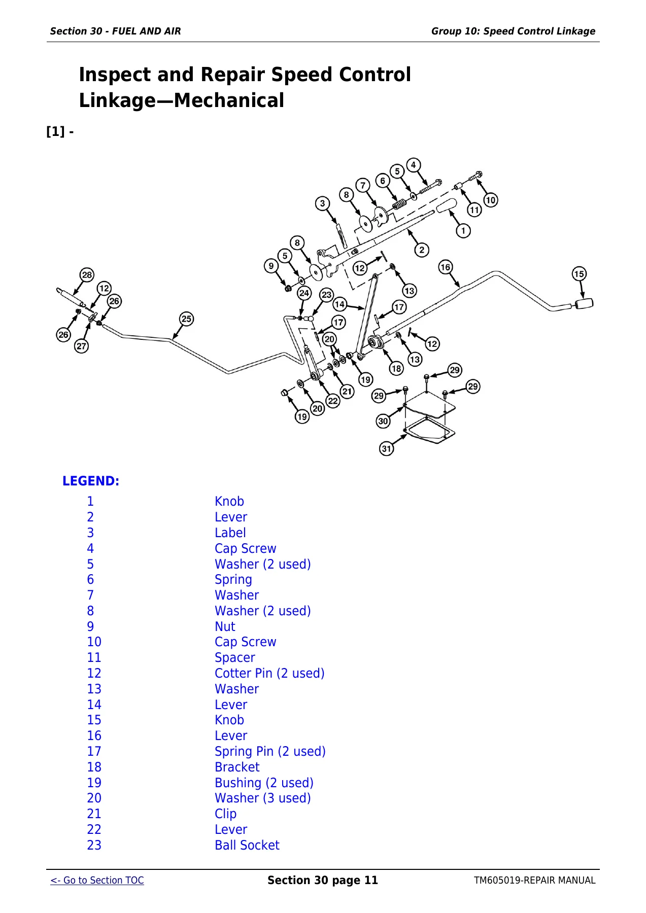
Inspect and Repair Speed Control Linkage—Mechanicalp. 143
Remove and Install Throttle Handle Assemblyp. 145
Remove and Install Throttle Handle Potentiometerp. 146
Remove and Install Throttle Pedal Assemblyp. 147
Remove and Install Throttle Pedal Potentiometerp. 148
Throttle Lever Friction Adjustmentp. 154
Adjust Throttle Linkagep. 155
+Group 15 – Air Intake Systemp. 156
Specificationsp. 156
Replace Air Cleaner Elements/Housingp. 157
Inspect and Service Air Intake Systemp. 159
Remove Turbochargerp. 160
Install Turbochargerp. 161
Turbocharger Break-Inp. 162
+Section 40 – ELECTRICAL REPAIRp. 166
+Group 05 – Battery, Starter and Alternatorp. 166
Specificationsp. 166
Prevent Battery Explosionsp. 166
Handling Batteries Safelyp. 167
Prevent Damage to Electrical Systemsp. 168
Connecting Booster Batteryp. 169
Charging Batteriesp. 169
Connecting Battery Cablesp. 170
Remove and Install Batteryp. 172
Remove and Install Starterp. 174
Starter Repair—Use CTMp. 174
Replace Alternatorp. 175
+Group 10 – Connectorsp. 177
Essential or Recommended Toolsp. 177
Other Materialp. 180
Use Electrical Insulating Compoundp. 180
Using High-Pressure Washersp. 181
Repair AMP Injection Pump Connectorp. 182
Remove Connector Body from Blade Terminalsp. 184
Repair CINCH Connectorsp. 186
Repair 32 and 48 Way CINCH Connectorsp. 188
Repair CPC Blade Type Connectorsp. 193
Repair CPC, Large MATE-N-LOC MATE-N-LOC is a trademark of AMP Incorporated and METRIMATE METRIMATE is a trademark of AMP Incorporated Pin Type Connectorsp. 194
Repair DEUTSCH Connectorsp. 196
Repair ITT Connectorp. 200
Repair Small MATE-N-LOC Socket Connectorp. 205
Repair Small MATE-N-LOC Pin Connectorp. 207
Repair (Pull Type) METRI-PACK METRI-PACK is a trademark of Delphi Packard Electric Systems Connectorsp. 208
Repair (Push Type) METRI-PACK Connectorsp. 210
Repair Molex Connectorp. 215
Repair SUMITOMO™ Connectorsp. 218
Repair Weather Pack Weather Pack is a trademark of Packard Electric Connectorp. 222
Repair YAZAKI™ Connectorsp. 225
+Group 15 – Wiring Harness Routingp. 229
Tractor Wiring Harness Replacementp. 229
Engine Harness—Tier 0/Tier 1p. 229
Engine Harness—Tier 3p. 231
Transmission Harnessp. 232
Chassis Harness—Cab Tractorsp. 235
Front Console Harness—Cab Tractorsp. 237
Cab Roof Harnessp. 239
Chassis/Front Console Harness—OOS Tractorsp. 241
+Group 20 – Electrical System Componentsp. 245
Service Equipment and Toolsp. 245
Other Materialp. 245
Specificationsp. 245
Replace Air Filter Restriction Switchp. 245
Replace Coolant Temperature Sensorp. 247
Replace Engine Speed Sensorp. 249
Replace Engine Oil Pressure Sensorp. 251
Remove and Install Instrument Panelp. 251
Replace Key Switchp. 253
Remove and Replace Light Switchp. 254
Replace Turn Signal Switchp. 256
Remove and Replace EH Directional Reverser Leverp. 257
Remove and Install Acceleration Potentiometer (Shuttle Control)p. 258
Replace Rear PTO Switchp. 259
Replace Neutral Start Switch (If Equipped)p. 261
Replace Horn Switchp. 261
Replace Hornp. 262
Replace Audible Alarmp. 263
Replace Starter Relayp. 264
Manifold Heater and Relay—Exploded View (If Equipped)p. 264
Replace Speakersp. 266
Replace Antennap. 267
Replace Wiper Control Switchp. 272
Remove And Install Wiper Motorp. 274
Replace Blower Control Switchp. 276
Replace A/C On/Off Switchp. 276
Replace A/C Temperature Control Switchp. 278
Replace Blower Motor Resistorp. 279
Replace Dome Lightp. 281
Replace Door Switchp. 282
Remove and Install ECU/PTR Controllers—OOSp. 283
Remove and Install ECU/PTR Controllers—Cabp. 284
+Group 25 – Auxiliary Lighting Componentsp. 285
Replace Seven Terminal Outlet Socket (If Equipped)p. 285
Replace Seven Terminal Outlet Socket (European) (If Equipped)p. 289
+Group 30 – Fuses And Relaysp. 290
Access Fuses and Relaysp. 290
Load Center Fuses and Relays-OOS (6100D/6110D/6125D with Dry Clutch and without Handbrake)p. 292
Load Center Fuses and Relays-OOS (6110D/6125D with Wet Clutch and without Handbrake)p. 294
Load Center Fuses and Relays-OOS (6100D/6110D/6125D with PowrReverser and without Handbrake)p. 296
Load Center Fuses and Relays-OOS (6115D/6130D/6140D without PowrReverser and without Handbrake)p. 298
Load Center Fuses and Relays-OOS (6115D/6130D/6140D with PowrReverser and without Handbrake)p. 300
Load Center Fuses and Relays-OOS—Behind Instrument Panelp. 301
Load Center Fuses and Relays-OOS—Behind Panel at Left Rear Corner of Operators Stationp. 301
Load Center Fuses and Relays—Cab (6100D/6110D/6125D with Dry Clutch and without Handbrake)p. 303
Load Center Fuses and Relays—Cab (6110D/6125D with Wet Clutch and without Handbrake)p. 305
Load Center Fuses and Relays—Cab (6100D/6110D/6125D with PowrReverser™ and without Handbrake)p. 307
Load Center Fuses and Relays—Cab (6115D/6130D/6140D without PowrReverser and without Handbrake)p. 309
Load Center Fuses and Relays—Cab (6115D/6130D/6140D with PowrReverser and without Handbrake)p. 311
Load Center Fuses and Relays—Cab—Behind Instrument Panelp. 312
Load Center Fuses and Relays—OOS (6115D/6130D with Dry Clutch and with Handbrake)p. 313
Load Center Fuses and Relays-OOS (6115D/6130D with Wet Clutch and with Handbrake)p. 315
Load Center Fuses and Relays-OOS (6115D/6130D with PowerReverser and with Handbrake)p. 317
Load Center Fuses and Relays-Cab (6115D/6130D with Dry clutch and with Handbrake)p. 319
Load Center Fuses and Relays-Cab (6115D/6130D with Wet clutch and with Handbrake)p. 321
Load Center Fuses and Relays-Cab (6115D/6130D with PowerReverser and with Handbrake)p. 323
Load Center Fuses and Relays—Cab (European)p. 325
Fusible Link Locationp. 327
Diode Location – Consolep. 328
+Group 35 – Lightingp. 330
Safety Rules When Replacing Halogen Bulbsp. 330
Replace Headlight Bulbsp. 331
Replace Auxiliary Field Light Bulbs – OOSp. 332
Replace Warning Light Bulb – Cabp. 334
Replace Tail Light Bulb – Cabp. 335
Replace Warning/Tail Light Bulbs – OOSp. 337
Replace Hazard Light Bulb – OOSp. 337
+Section 50 – POWER TRAINp. 340
+Group 00 – Towingp. 340
Towing Tractorp. 340
Adjust Range Shift Lever and Tow Lockp. 342
+Group 05 – Component Removalp. 343
Essential or Recommended Toolsp. 343
Other Materialp. 343
Specificationsp. 344
Transaxle Separation and Repair—Use CTMp. 344
Remove and Install Rear PTO Drive Shaft Assemblyp. 346
Remove and Install Final Drive Assemblyp. 350
Remove and Install Clutchp. 357
Remove, Inspect and Install MFWD Drive Shaftp. 360
Remove and Install MFWD Drop Gearboxp. 364
+Group 10 – PTOp. 367
PTO Housing Repair—Use CTMp. 367
Remove, Inspect and Install PTO Lever and Linkagep. 368
Determine PTO Clutch Linkage Adjustment Procedurep. 372
Adjust PTO Clutch Linkage—(OOS)p. 374
Adjust PTO Clutch Cable—(Cab Tractors)p. 378
+Group 15 – Clutchp. 380
Essential or Recommended Toolsp. 380
Other Materialp. 380
Specificationsp. 381
Separate and Install Engine-to-Clutch Housingp. 382
Remove and Install Clutch Linkage (Collar Shift Transmission)p. 395
Remove and Install Clutch Linkage (Synchronized Transmission)p. 397
Remove and Install Clutch Pedal Position Sensor—Wet Clutchp. 399
Adjust Interlock Cablep. 401
Adjust Clutch Pedal and Linkagep. 402
+Group 25 – Separationp. 405
Park Tractorp. 405
Remove Batteryp. 406
Relieve Hydraulic Pressurep. 406
Drain Hydraulic Oilp. 407
Remove Fuel Tankp. 409
Remove Operator Cabp. 411
Remove Operator Stationp. 424
Remove Complete Transmission Harness Cab / OOSp. 432
Remove MFWD Drive Shaftp. 434
Split Tractorp. 436
+Section 60 – STEERING AND BRAKE REPAIRp. 447
+Group 05 – Steering Repairp. 447
Specificationsp. 447
Remove and Install Steering Wheelp. 448
Remove and Install Steering Columnp. 449
Remove and Install Steering Valve (Open Operator Station)p. 451
Remove and Install Steering Valve (Cab Tractors)p. 454
Start-Up Procedure After Hydraulic System Repairsp. 455
+Group 10 – Front Axle—2WDp. 457
Essential or Recommended Toolsp. 457
Other Materialp. 458
Specificationsp. 460
Remove Front Axle—2WDp. 461
Install Front Axle—2WDp. 464
Disassemble Front Axle—2WDp. 466
Assemble Front Axle—2WDp. 468
Adjust Knuckle and Spindle Assembly Axial Play—2WDp. 471
Assemble Wheel Hub—2WDp. 473
Adjust Wheel Bearings—2WDp. 474
Remove and Install Axle Pivot Pins/Bushings—2WDp. 475
Install Tie Rod—2WDp. 477
Check And Adjust Toe-In—2WDp. 479
Remove and Install Steering Cylinder—2WDp. 481
Disassemble, Inspect and Assemble Steering Cylinder—2WDp. 484
+Group 15 – Front Axle—MFWDp. 487
Essential or Recommended Toolsp. 487
Specificationsp. 488
Remove, Inspect and Install Tie Rod Assembly—MFWDp. 488
Check And Adjust Toe-In—MFWDp. 490
Remove and Install Steering Cylinder—MFWDp. 492
Disassemble, Inspect and Assemble Steering Cylinder—MFWDp. 495
Remove Front Axle—MFWDp. 496
Install Front Axle—MFWDp. 499
+Group 20 – Brake Repairp. 501
Specificationsp. 501
Remove and Replace Brake Pedals and Linkagep. 502
Adjust Brake Linkage and Pedal Travelp. 504
Checking and Adjusting Hand Brake Leverp. 506
+Section 70 – HYDRAULIC REPAIRp. 510
+Group 05 – Hydraulic Pump and Oil Coolerp. 510
Other Materialp. 510
Specificationsp. 511
Service Parts Kitsp. 511
Remove and Install Hydraulic Oil Coolerp. 512
Remove and Install Hydraulic Pumpp. 516
Disassemble and Assemble Hydraulic Pumpp. 522
Start-Up Procedure After Hydraulic System Repairsp. 524
+Group 10 – Rockshaftp. 525
Essential or Recommended Toolsp. 525
Other Materialp. 525
Specificationsp. 526
Service Parts Kitp. 526
Remove, Inspect and Install Hitch Rate-of-Drop Valvep. 527
Remove and Install Rockshaft Control Valvep. 531
Disassemble, Inspect and Assemble Rockshaft Control Valvep. 538
Remove and Install Rockshaft Housingp. 543
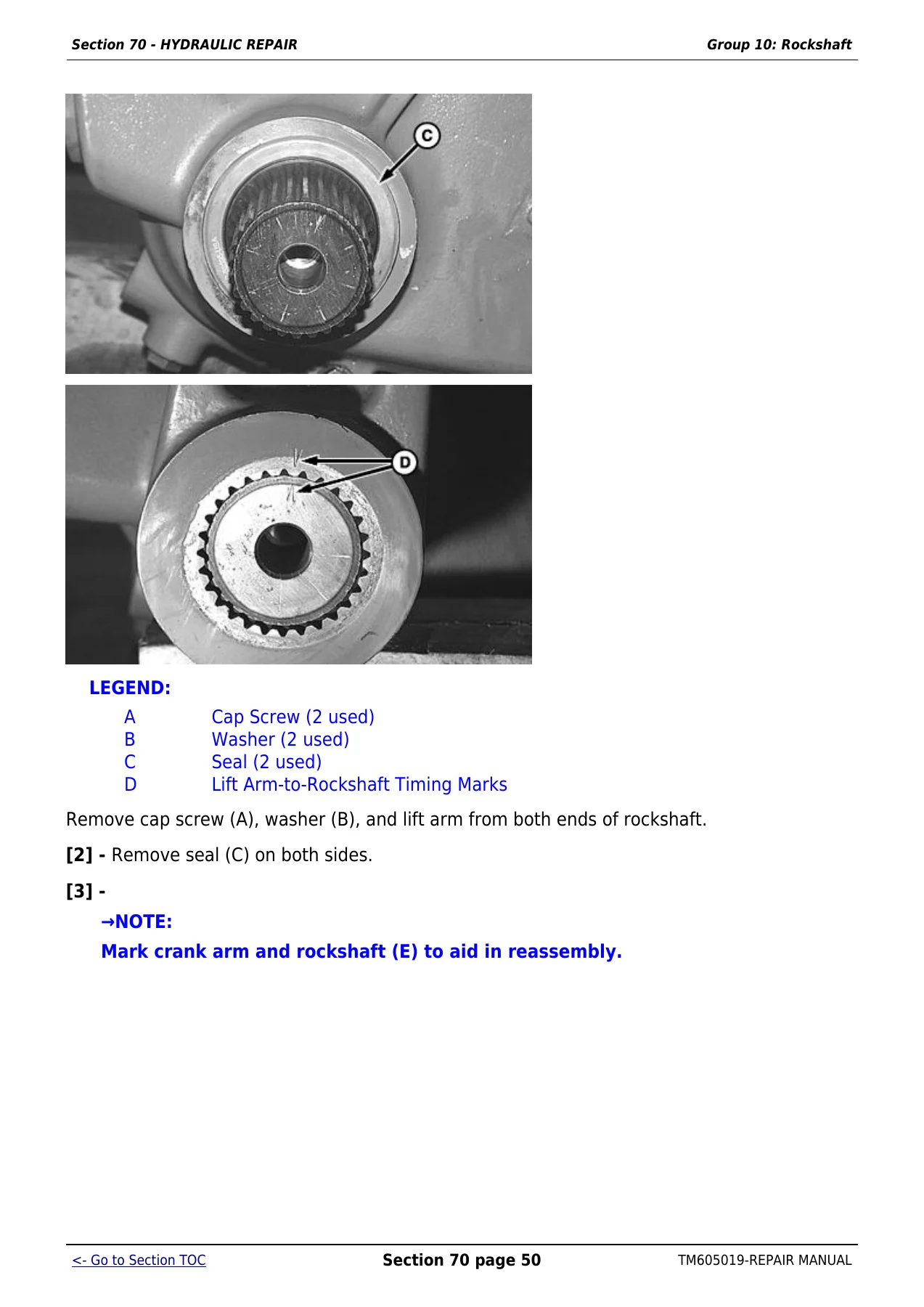
Disassemble and Assemble Rockshaftp. 557
Remove and Install Rockshaft Cylinderp. 564
Remove, Inspect and Replace Rockshaft Internal Linkagep. 569
Disassemble and Assemble Rockshaft Control Linkage and Leversp. 571
Rockshaft Internal Linkagep. 572
Adjust Rockshaft Internal Linkage (Lift Arm Raise Limit)p. 573
Adjust Rockshaft Control Lever (OOS Tractors)p. 575
Adjust Rockshaft Control Lever (Cab Tractors)p. 578
Adjust Load Sense Linkage (OOS Tractors)p. 581
Adjust Load Sense Linkage (Cab Tractors)p. 584
+Group 15 – Lubrication Systemp. 586
Specificationsp. 586
Remove and Install Lubrication System Relief Valvep. 587
+Group 20 – Selective Control Valve (SCV)p. 591
Other Materialp. 591
Specificationsp. 591
Service Parts Kitsp. 591
Remove and Install Selective Control Valvep. 592
Disassemble, Inspect and Assemble Selective Control Valvep. 596
Rear Triple Deluxe SCV Kick-Out Relief Valve Adjustmentp. 608
+Group 25 – Mid-Mount Selective Control Valve (SCV)p. 613
Other Materialp. 613
Specificationsp. 613
Remove and Install Mid-Mount Selective Control Valvep. 614
Disassemble, Inspect, and Assemble Dual Mid-Mount Control Valvep. 617
Inspect and Repair Joystick and Linkagep. 623
Adjust Mid-Mount Control Valve Cablep. 628
+Group 30 – Hydraulic Trailer Brake Valvep. 630
Specificationsp. 630
Remove, Inspect and Install Hydraulic Trailer Brake Valvep. 631
Hydraulic Trailer Brake Valve Control Cable Adjustmentp. 634
+Section 80 – MISCELLANEOUS REPAIRp. 636
+Group 05 – Hood and Fendersp. 636
Specificationsp. 636
Remove and Install Front Fenderp. 636
Remove and Install Fender Extensions—OOSp. 637
Remove and Install Fenders—Cab Tractorsp. 639
Remove and Install Hoodp. 648
+Group 10 – 3-Point Hitchp. 650
Essential or Recommended Toolsp. 650
Other Materialp. 650
Specificationsp. 650
Inspect and Repair Stabilizer Chainsp. 652
Inspect and Repair Standard Lift Linkp. 655
Inspect and Repair Adjustable Lift Linkp. 657
Inspect and Repair Center Linkp. 659
Remove and Install Draft Link Pivot Shaftp. 660
Remove and Install Drawbarp. 668
+Group 15 – Wheelsp. 670
Essential or Recommended Toolsp. 670
Specificationsp. 672
Remove and Install Front and Rear Wheelsp. 673
Remove and Install Wheel Rimp. 675
Rear Ballastp. 677
+Group 20 – Front Supportp. 679
Essential or Recommended Toolsp. 679
Specificationsp. 679
Remove, Inspect and Install Front Supportp. 681
+Group 25 – Trailer Mounting and Swinging Drawbarp. 688
Guide Rails for Height-Adjustable Trailer Hitchp. 688
Checking the Manually-Operated Hitch (EEC Type) for Wearp. 691
Checking the Manually-Operated Hitch (CUNA Type) for Wearp. 693
Checking the Tow-Hook for Wearp. 694
Checking the Hitch Ball for Wearp. 695
Checking the Swinging Drawbar for Wearp. 697
+Section 90 – OPEN OPERATOR STATION REPAIRp. 700
+Group 05 – Seat and Supportp. 700
Specificationsp. 700
Remove and Install Seat and Supportp. 700
+Group 10 – ROPSp. 701
Specificationsp. 701
Check ROPSp. 701
Disassemble ROPS Canopyp. 702
Remove and Install ROPSp. 704
+Group 15 – Operator Platformp. 711
Other Materialp. 711
Specificationsp. 711
Remove Operator Stationp. 712
Install Operator Stationp. 721
+Group 20 – Cowl Repairp. 731
Remove and Install Cowlp. 731
+Section 95 – CAB—OPERATOR STATION REPAIRp. 735
+Group 00 – Removal and Installation of Componentsp. 735
Service Equipment and Toolsp. 735
Essential Toolsp. 735
Specificationsp. 736
Remove, Inspect, and Install Cab Interior Recirculating Air Filtersp. 737
Remove, Inspect, and Install Exterior Cab Intake Air Filtersp. 739
Remove and Install Headlinerp. 742
Remove and Install Fender Consolep. 745
Remove and Install Cowlp. 747
Remove and Install Windshieldp. 749
Remove and Install Rear Windowp. 753
Remove and Install Front Lower Windowsp. 754
Remove and Install Rear Lower Windowp. 756
Remove and Install Side Windowsp. 758
Remove and Install Cab Doorsp. 761
Remove and Install Cab Roofp. 766
Remove and Install Safety Exit Doorp. 770
Installing Door Lockp. 772
Remove Operator Cabp. 774
Install Operator Cabp. 787
+Group 05 – Selective Control Valve Cable Adjustmentp. 791
Specificationsp. 791
Remove and Install Selective Control Valve Cable (Cab Tractors)p. 792
+Group 10 – Air Conditioning Systemp. 797
Essential Toolsp. 797
Service Equipment and Toolsp. 801
Other Materialp. 802
Specificationsp. 803
Service Parts Kitsp. 803
Recover/Recycle Air Conditioning Refrigerantp. 804
Replace Air Conditioning Receiver-Dryerp. 807
Remove, Inspect, and Install Air Conditioning Condenserp. 809
Remove, Inspect, and Install Air Conditioning Compressorp. 812
Test Volumetric Efficiency of Compressorp. 814
Test Compressor Shaft Seal Leakagep. 818
Disassemble and Assemble Compressor Clutchp. 820
Disassemble, Inspect, and Assemble Compressorp. 824
Check Compressor Clutch Hub Clearancep. 828
Inspect Compressor Manifoldp. 828
Remove and Install Compressor Relief Valvep. 830
Remove and Install the Evaporator and Expansion Valvep. 831
Arrangement of Condensation Water Drain Hosesp. 833
Remove and Install A/C Thermostat Switchp. 835
Adjust Thermostat Switch Bowden Cablep. 838
Remove and Install the High/Low Pressure Switchp. 840
Expansion Valve Bench Testp. 842
Refrigerant Oil Informationp. 844
Check Compressor Oil Chargep. 845
Determine Correct Refrigerant Oil Chargep. 846
Add Refrigerant Oil to Systemp. 847
System Informationp. 849
Flush Air Conditioning Systemp. 851
Evacuate Air Conditioning Systemp. 857
Charge Air Conditioning Systemp. 859
+Group 15 – Heating Systemp. 861
Remove and Install Radiatorp. 861
Remove and Install Fan Motorsp. 863
Remove and Install Fan Motor Resistorsp. 865
Remove and Install Heater Valvep. 867
Adjust Heater Valve Bowden Cablep. 869
+Group 20 – Seatp. 870
Remove and Install Seat and Supportp. 870
+Section 99 – SPECIAL TOOLSp. 872
+Group 05 – DEALER-FABRICATED TOOLSp. 872
DFRW20—Compressor Holding Fixturep. 872
Short Adapterp. 872
+Service Toolsp. 874
JT02098 — Air Conditioning Flushing Kitp. 874
JT07120 — Load Valve Assemblyp. 874
JT03105 — Connector (1/2 (m) NPT X 1/4 (f) NPT)p. 875
JT03261 — Coupler (1/4 (m) NPT)p. 875
JT05497 — Hose Assembly, 3048 mm (120 in.) Longp. 876
JT07117 — Three-Gauge Manifoldp. 877
JT03348 — Tee Fitting (1/2 (f) NPT x 1/2 (f) NPT x 1/2 (f) NPT)p. 877
R36659 — Hydraulic Jumper Hose (3 ft)p. 878
- Section 80 – Miscellaneous Repair
- Hood and fenders; three-point hitch links and drawbar; wheels, rims and rear ballast; front support; trailer hitch, tow-hook, hitch-ball and swinging-drawbar wear checks
- Section 90 – Open Operator Station Repair
- Seat and support, ROPS inspection/removal, operator platform removal/installation and cowl repair
- Section 95 – Cab – Operator Station Repair
- Cab filters, headliner, console, cowl, windows, doors, roof and cab removal/installation; SCV cable; air-conditioning recovery, compressor, condenser, evaporator, switches, refrigerant oil, evacuation and charging; heating system and seat
- Section 99 – Special Tools
- Dealer-fabricated tools and listed service tools used with air-conditioning and hydraulic service work
Taken as a whole, TM605019 supports substantial chassis, hydraulic, power-train, electrical and operator-station work rather than limiting the technician to routine maintenance. Procedures are supported by photographs, component callouts, exploded illustrations, adjustment instructions and specification blocks so disassembly and reassembly can be tied back to the values and hardware shown for the repair.
Engine, Hydraulic and Power-Train Depth
For engine-related work, the manual covers removing and installing the engine, engine oil pan and rocker arm cover, access to front and rear crankshaft seals, front timing cover access, belt service, radiator and cooling-package service, water-pump procedures, and cooling-system pressure testing. It also supplies machine-specific mounting torques and capacities used during those jobs. Some internal engine procedures explicitly direct the technician to the applicable component technical manual (CTM), so TM605019 should be used together with the referenced CTM when the procedure calls for it.
The hydraulic section is particularly detailed. It includes removal and installation of the hydraulic oil cooler and pump, pump disassembly and assembly, system start-up after hydraulic repairs, rockshaft valve and housing work, cylinder and linkage service, SCV disassembly and adjustment, mid-mount valve and joystick work, and hydraulic trailer-brake valve procedures. The general specifications identify an open-center system with an external gear pump, an implement-pump capacity of 66.62 L/min (17.6 gpm) at 2100 rpm, and maximum pressure of 19,500 kPa (2830 psi). Drain-and-refill data includes 58 L (15.3 gal) for the transmission case and 6.5 L (6.9 qt) for the MFWD axle housing.
Power-train coverage follows the machine through PTO service, clutch arrangements, drive-shaft and final-drive removal, transmission-related component removal and major tractor separation. The section includes procedures for separating the engine from the clutch housing and splitting the tractor, along with linkage and cable adjustments for the PTO and clutch systems. Where complete transaxle or PTO housing repair requires a separate CTM, the manual says so directly and keeps the machine-level removal, installation and adjustment information in TM605019.
Electrical, Steering and Operator Station Repairs
The electrical repair material extends beyond battery and starter replacement. It includes numerous connector families and terminal-repair methods, wiring-harness routing for Tier 0/Tier 1 and Tier 3 engine configurations, transmission and chassis harnesses, cab and open-station harness routes, switches, sensors, instrument components, controllers, lighting, fuses and relays. This is useful when a repair requires correct routing, connector identification or access to a component rather than only a basic electrical specification.
Steering and brake sections cover both 2WD and MFWD axle arrangements. Procedures include steering valve access, axle removal and assembly, tie rods, toe-in checks, wheel-bearing work, steering-cylinder service, brake linkage and pedal adjustment. The open operator station section adds seat, ROPS, platform and cowl work, while the cab section expands into doors, glass, roof, cab removal, climate-control service and related control adjustments. That range makes this John Deere 6100D-6140D repair manual useful for repairs that cross several tractor systems during the same job.
Get the Repair Procedures in One PDF
The John Deere 6100D 6110D 6115D 6125D 6130D 6140D Tractor Repair Technical Service Manual TM605019 2011 PDF gives owners and experienced technicians a structured reference for component removal and installation, repair and adjustment work, hydraulic service, electrical repairs, steering and brake work, power-train procedures, cab and open-station repairs, torque values, capacities and service specifications. Using the procedures and specifications printed for these tractors helps keep reassembly, adjustment and service work tied to the documented values instead of relying on memory or generic repair information.
Delivery is instant as a PDF after purchase, with no shipping delay. Open it on a computer, tablet or phone, keep it available at the workbench, and print the pages you need for the job.

Reviews
There are no reviews yet.