
John Deere 8130 8230 8330 8430 8530 Tractors Operation and Test Technical Manual TM2280
Original price was: $44.95.$27.95Current price is: $27.95.
The complete John Deere TM2280 Operation and Test Technical Manual for 8130, 8230, 8330, 8430, and 8530 tractors — full diagnostic trouble code guides, electrical schematics, hydraulic and transmission tests, and system diagnosis in a single PDF.
Description
This John Deere 8130, 8230, 8330, 8430, and 8530 Tractors Operation and Test Technical Manual TM2280 is the dealer diagnostic and testing reference for the 8×30 series row-crop tractors. It walks an experienced technician through every diagnostic trouble code in the machine, every observable symptom table, and every system-level test used to isolate failures in the electrical, transmission, hydraulic, steering, brake, and operator-station systems. At 5,645 pages it is far more than a repair guide — it is the testing and diagnosis brain of the service department.
File Details
- Manual type: Operation and Test Technical Manual
- Brand: John Deere
- Models covered: 8130, 8230, 8330, 8430, 8530 tractors
- Document number: TM2280
- Publication date: 11AUG09
- Language: English
- Page count: 5,645
- File format: PDF
- Companion manuals referenced: TM2270 Repair, CTM385, CTM400, CTM77, TM1061, TM2240, TM2820
Chapters Covered
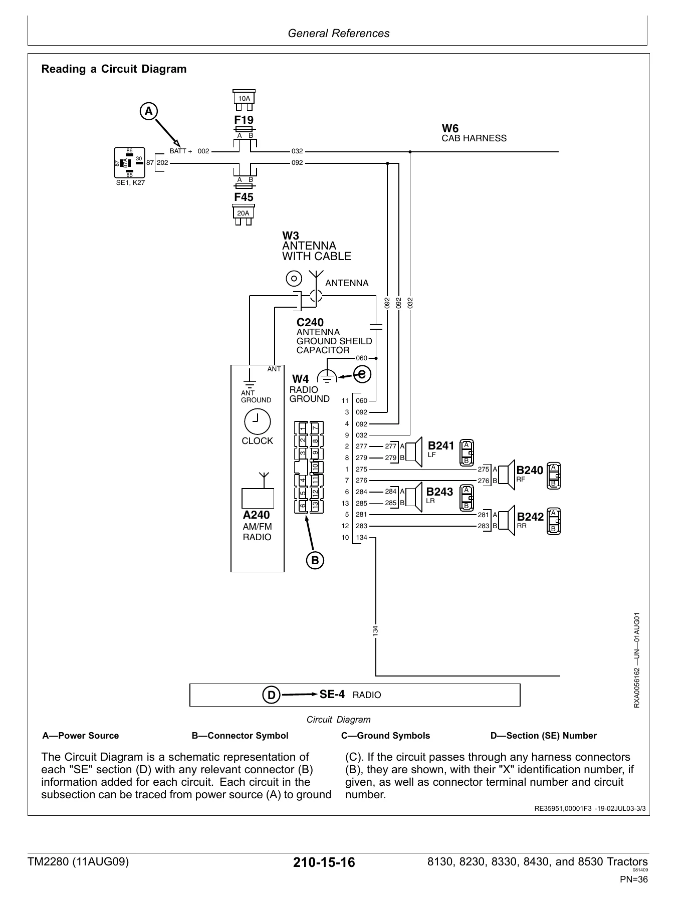
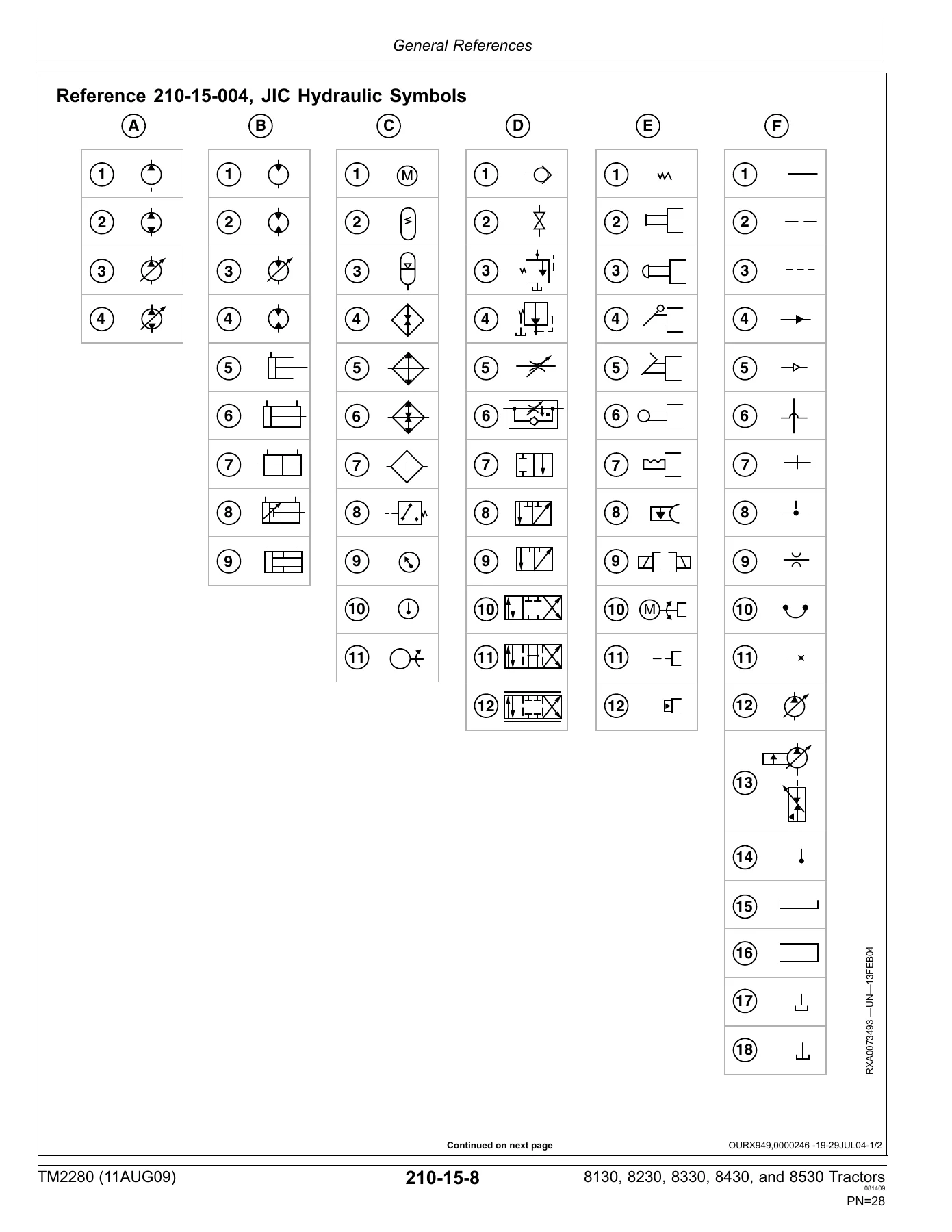
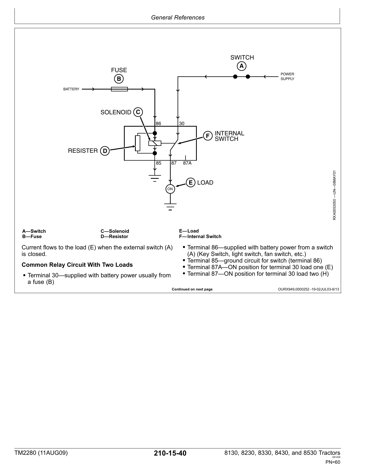
- Section 210 General — Group 05 Safety, Group 15 General References (torque values, glossary, JIC hydraulic symbols, wiring diagram reading, seven-step electrical procedure, circuit types and malfunctions, relays, DMM use)
- Section 211 Diagnostic Trouble Codes — ACU, ASU, ATC, BRC, CAB, CCU, CLC, ECU, HCC, HCU, HVI, ICU, PTI, PTP, SCC, SCO, SCU, SFA, SSU, SUP, SVI through SVVII, TEC, VLC
- Section 212 Observable Symptoms — Electrical, Control Units, Powershift Transmission, AutoPowr / IVT Transmissions, Drive Systems, Steering and Brakes, Hydraulics, Operator Station
- Section 213 System Diagnosis — Electrical, CAN System Diagnosis, Powershift Transmission, AutoPowr / IVT Transmission, Drive Systems, Steering and Brakes, Hydraulic System, Operator Station
- Section 220 Engines — Test and References, Theory of Operation
- Section 230 Fuel and Air — Theory of Operation
- Section 240 Electrical — Load Center Fuses and Relays, Operational Checks, Functional Schematics, Connector Information, Harness Information, plus subsections SE01 through SE20 covering power supply, starting and charging, seat, ATC, mirrors, radio and dome lamp, cab load center, accessory connectors, CAN termination, corner post display, CAB control unit, powertrain VLC and CCU, armrest control unit, SCU / HCU / BRC / SFA, SCO, ECU Level 14, JDLINK, GreenStar display, and SSU
- Section 245 Control Units — General References plus per-unit groups for ACU, ASU, ATC, BRC, CAB, CCU, CLC, ECU, HCC, HCU, HVI, ICU, PTI, PTP, SCC, SCO, SCU, SFA, SSU, SUP, SVI-VII, TEC, and VLC
- Section 250 Powershift Transmission — Preliminary Checks, Operational Checks, Tests and Adjustments, Theory of Operation, Schematics and Diagrams
- Section 251 AutoPowr / IVT Transmission — Preliminary Checks, Operational Checks, Tests and Adjustments, Theory of Operation, Schematics and Diagrams
- Section 256 Drive Systems — Preliminary Checks, Operational Checks, Tests and Adjustments, Theory of Operation, Schematics and Diagrams
- Section 260 Steering and Brakes — Preliminary Checks, Operational Checks, Tests and Adjustments, Theory of Operation, Schematics and Diagrams
- Section 270 Hydraulics — Preliminary Checks, Operational Checks, Tests and Adjustments, Theory of Operation, Schematics and Diagrams
- Section 290 Operator Station — Preliminary Checks, Operational Checks, Tests and Adjustments, Theory of Operation, Schematics and Diagrams
- Section 299 Service Tools — Dealer Fabricated Tools, Service Tools and Kits
What the Operation and Test Manual Gives You
Where the Repair manual tells you how to remove and rebuild parts, TM2280 tells you how to find the fault. Every diagnostic trouble code listed in Section 211 includes the code-caused-by condition, alarm level, displayed text on the CommandCenter, control unit response, required tools, and a step-by-step diagnosis path with code operational checks, system checks, electrical circuit checks, and an intermittent-failure evaluation. Sections 212 and 213 take the opposite approach — starting from what the operator actually observes (hard starting, no motion, slipping clutch, wrong oil pressure reading) and narrowing it down to the circuit or sensor at fault.
The electrical section is where this manual earns its place on the bench. Wiring is organized by numbered circuit and color code, and every functional schematic carries component identification letters, ground points, power leads, and connector cross-references. Subsections SE01 through SE20 break the tractor down into logical electrical systems — charging, starting, seats, HVAC, mirrors, radio, lighting, CAN, corner post, cab control, powertrain, armrest, hydraulic control units, engine ECU level 14, JDLINK, GreenStar, and steering. The included CAN system diagnosis group and connector / harness information let you chase intermittent faults without pulling the whole harness apart.
Powertrain coverage is split between the traditional Powershift (PST) and the AutoPowr / IVT transmissions, each with its own preliminary checks, operational checks, tests and adjustments, theory of operation, and schematics. Hydraulics covers the clean oil reservoir, filter restriction monitoring, selective control valves SCV I through VII, hitch control, secondary hydraulic control, and the front hitch option. Steering and brakes round out the chassis with pressure sensor tests, calibration procedures, and brake valve checks. A dedicated Service Tools section at the back lists dealer-fabricated tools and the service tool kits called out throughout the test procedures.
Because this is a test-and-diagnosis manual written for the technician, it assumes familiarity with John Deere’s control unit architecture — CAN messaging, control unit addresses, DTCs, and calibration routines. It is not an operator’s manual and does not duplicate the owner-level content. What it does contain is the exact test values, sensor voltage windows, current limits, and step-by-step fault isolation logic that the service department uses when a customer complaint cannot be resolved by swapping parts.
Who This Manual Is For
Independent repair shops working on 8×30 series tractors, dealer technicians who need the diagnostic side of the service library in one place, and owners running their own fleet who want to diagnose electrical and hydraulic faults before booking a service call. The manual references companion publications (Repair TM2270, engine CTM385 and CTM400, GreenStar TM1061, RTK TM2820) for procedures that live outside the Operation and Test scope — those are not included here, and the reader should expect to source them separately where a procedure explicitly sends you to them.
Get Instant Access
IMAGES PREVIEW
Fault-finding on a modern high-horsepower tractor without the manufacturer’s test procedures turns into guesswork and parts-swapping. The John Deere 8130, 8230, 8330, 8430, and 8530 Tractors Operation and Test Technical Manual TM2280 puts the full diagnostic library — DTC tables, symptom charts, system tests, wiring schematics, hydraulic test values, and calibration routines — on your screen or in your hand. Delivered as an instant-download PDF after checkout, no shipping and no waiting, ready to print specific pages for the shop or carry on a laptop or tablet into the field. Keep it next to the machine and diagnose confidently the way the factory intended.
Reviews
There are no reviews yet.