
★ TRUSTED BY 321,897+ PROFESSIONALS WORLDWIDE
🏒
Trusted Business
Verified & Licensed
πŸ›‘οΈ
Virus Free Files
100% Safe Downloads
πŸ”’
Secure Payment
SSL Protected
⚑
Instant Delivery
Available Immediately
Sale!

John Deere PowerTech 10.5L 12.5L Level 6 Lucas EUI Fuel Systems CTM188 Component Technical Manual

Original price was: $34.95.Current price is: $22.95.

John Deere CTM188 Component Technical Manual covering the dual rail and single rail fuel systems plus Level 6 electronic fuel control on PowerTech 10.5 L and 12.5 L diesel engines with Lucas EUIs. Repair, theory of operation, diagnostics, tools and specifications for 6105 and 6125 engine applications.

⚑
Instant PDF Download
Available immediately
πŸ’Ύ
Save to Your Device
Download & keep forever
πŸ›‘οΈ
Antivirus Scanned
100% virus-free
🌍
Trusted Worldwide
175,000+ customers

Description

John Deere PowerTech 10.5L 12.5L Level 6 Lucas EUI Fuel Systems CTM188 Component Technical Manual

This is the John Deere Component Technical Manual CTM188, published 14MAY03 in English, covering the dual rail and single rail fuel systems on PowerTech 10.5 L and 12.5 L diesel engines equipped with John Deere Level 6 electronic fuel control and Lucas electronic unit injectors (EUIs). It is the third volume in a three-manual set and consolidates the single rail fuel system, dual rail fuel system and electrical engine control repair procedures that previously appeared in CTM100 Groups 35, 36 and 45.

The manual is written for the experienced technician. It is divided into repair, theory of operation and diagnostics, and it covers both the earlier dual rail fuel system used on 10.5 L engines up to serial number 003763 and 12.5 L engines up to serial number 010966, and the later single rail fuel system used from 10.5 L serial number 003764 and 12.5 L serial number 010967 onward. Both 6105 and 6125 engine families are addressed.

File Details

  • Manual type: Component Technical Manual (CTM)
  • Brand: John Deere
  • Engine series: PowerTech 10.5 L & 12.5 L Diesel Engines
  • Document number: CTM188
  • Edition/date: 14MAY03 (English)
  • Language: English
  • File format: PDF
  • Companion manuals referenced: CTM100 (Base Engine), CTM115 (Lucas Electronic Fuel Systems with Lucas EUIs), CTMY7 (Alternators and Starter Motors), CTM67 (OEM Engine Accessories). Complete set available as CTM650 Binder Set.

Chapters Covered

  • Section 01 β€” General Information
    • Group 000 β€” Safety
    • Group 001 β€” Engine Identification (model designation, serial number plate, option code label, application chart, distinguishing ECUs)
    • Group 002 β€” Fuels (lubricants, coolant, Tier 1 diesel, Tier 2 diesel, bio-diesel, lubricity, DIESELSCAN fuel analysis)
  • Section 02 β€” Repair and Adjustments
    • Group 090 β€” Dual Rail Fuel System Repair and Adjustment
    • Group 091 β€” Single Rail Fuel System Repair and Adjustment
    • Group 110 β€” Electrical Engine Control Repair and Adjustment (sensors, connectors)
  • Section 03 β€” Theory of Operation
    • Group 130 β€” Electronic Fuel System Operation
    • Group 140 β€” Electrical Control System Operation
  • Section 04 β€” Diagnostics
    • Group 150 β€” Observable Diagnostics and Tests
    • Group 160 β€” Trouble Code Diagnostics and Tests
  • Section 05 β€” Tools
    • Group 170 β€” Repair Tools
    • Group 180 β€” Diagnostic Service Tools
  • Section 06 β€” Specifications
    • Group 200 β€” Repair Specifications
    • Group 210 β€” Diagnostic Specifications (application-specific sensor, torque curve, governor and ECU terminal data)

Complete PDF Bookmark Tree

Complete Bookmarks

The complete bookmarks in the β€œJohn Deere PowerTech 10.5L 12.5L Level 6 Lucas EUI Fuel Systems CTM188 Component Technical Manual” are as follows:

Contentsp. 6
General Informationp. 8
Safetyp. 10
Handle Fluids Safelyβ€”Avoid Firesp. 10
Handle Starting Fluid Safelyp. 10
Service Cooling System Safelyp. 11
Prevent Battery Explosionsp. 11
Prepare for Emergenciesp. 12
Handling Batteries Safelyp. 13
Avoid High-Pressure Fluidsp. 14
Wear Protective Clothingp. 14
Service Engines Safelyp. 15
Work In Ventilated Areap. 15
Work in Clean Areap. 16
Remove Paint Before Welding or Heatingp. 16
Avoid Heating Near Pressurized Fluid Linesp. 17
Illuminate Work Area Safelyp. 17
Practice Safe Maintenancep. 18
Use Proper Toolsp. 18
Dispose of Waste Properlyp. 19
Live With Safetyp. 19
Engine Identificationp. 20
Engine Model Designationp. 20
Engine Serial Number Plate Informationp. 21
Engine Option Code Labelp. 22
Engine Application Chartp. 23
Distinguishing ECUsp. 24
Fuelsp. 26
Lubricants and Coolantp. 26
Diesel Fuel – Tier 1p. 26
Diesel Fuel – Tier 2p. 27
Bio-Diesel Fuelp. 29
Lubricity of Diesel Fuelp. 30
DIESELSCANβ„’ Fuel Analysisp. 30
Repair and Adjustmentsp. 32
Dual Rail Fuel System Repair and Adjustmentp. 34
Dual Rail Fuel System Components (Earlier Engines)p. 34
Replace Final (Secondary) Fuel Filter Elementp. 36
Replacing Primary Fuel Filter/Water Separatorp. 37
Remove and Install Air Purge Valvep. 39
Remove and Install Primary Fuel Filter Check Valvep. 40
Remove and Install Fuel System Surge Tank (6125ADW01/70 Engines)p. 41
Remove and Install Dual Rail Fuel Supply Pumpp. 42
Remove and Install Dual Rail Fuel Manifoldp. 44
Inspect Fuel Pressure Regulating Valve and Return Check Valvep. 46
Remove and Install Electronic Unit Injectorsp. 47
Adjust Electronic Unit Injector Preloadp. 52
Replace Electronic Unit Injector O-Ringsp. 54
Replace Electronic Unit Injector Thrust Sleeve, Pad and O-Ringp. 54
Flush Fuel Railsp. 55
Bleed Fuel Systemp. 56
Single Rail Fuel System Repair and Adjustmentp. 58
General Informationp. 58
Single Rail Fuel System Components (Later Engines)p. 59
Fuel Filter/Water Separator Assemblyp. 60
Replacing Fuel Filter/Water Separatorp. 61
Remove and Install Low Pressure Regulating Valvep. 65
Remove and Install High Pressure Regulating Valvep. 66
Remove and Install 100 Micron Internal Filter Housing Screen Insertp. 68
Remove and Install Fuel Filter Check Valvep. 69
Remove and Install Primer Pumpp. 69
Remove and Install Single Rail Fuel Supply Pumpp. 70
Remove and Install Electronic Unit Injectors (Single Rail Fuel System)p. 72
Adjust Electronic Unit Injector Preloadp. 77
Replace Electronic Unit Injector O-Ringsp. 79
Replace Electronic Unit Injector Thrust Sleeve, Pad and O-Ringp. 79
Bleed Fuel Systemp. 80
Electrical Engine Control Repair and Adjustmentp. 82
John Deere Level 6 Electronic Control Systemp. 82
Remove and Install Coolant Temperature Sensorp. 83
Remove and Install Fuel Temperature Sensor (Dual Rail System)p. 84
Remove and Install Fuel Temperature Sensor (Single Rail System)p. 84
Remove and Install Fuel Pressure Sensor (Single Rail Fuel System)p. 85
Remove and Install Water-in-Fuel Sensor (Single Rail Fuel System)p. 86
Remove and Install Oil Pressure Sensorp. 87
Remove and Install Manifold Air Temperature (MAT) Sensorp. 88
Remove and Install Manifold Absolute Pressure (MAP) Sensorp. 89
Remove and Install Camshaft Position Sensorp. 90
Remove and Install Crankshaft Position Sensorp. 91
Connectorsp. 93
Use Electrical Insulating Compoundp. 93
Using High-Pressure Washerp. 93
Repair WEATHERPACKβ„’ Connectorp. 94
Remove Blade Terminals from Connector Bodyp. 97
Repair (Pull Type) METRI-PACKβ„’ Connectorsp. 98
Repair (Push Type) METRI-PACKβ„’ Connectorsp. 100
Repair DEUTSCHβ„’ Connectorsp. 103
Repair CINCH Connectorsp. 106
Theory of Operationp. 108
Electronic Fuel System Operationp. 110
About This Groupp. 110
Low Pressure Dual Rail Fuel Supply System Operationp. 111
Electronic Unit Injector (EUI) Operation on the Dual Rail Fuel Systemp. 113
Low Pressure Single Rail Fuel Supply System Operationp. 117
Electronic Unit Injector (EUI) Operation on the Single Rail Fuel Systemp. 119
Electrical Control System Operationp. 124
Electronic Control System Glossary of Termsp. 124
Electronic Control System Overviewp. 127
Electronic Control System Operationp. 129
Monitoring Engine Parametersp. 129
Measuring Temperaturep. 130
Measuring Pressurep. 132
Water In Fuel Sensorp. 133
Measuring Throttle Positionp. 133
Determining Engine Speed and Piston Positionp. 138
Engine Control Unit (ECU)p. 143
Controller Area Network (CAN)p. 145
Cruise Control Operationp. 145
Engine Protectionp. 146
Different Derate Programsp. 146
Multiple Torque Curve Selectionp. 147
Governor Droop Mode Selectionp. 148
Engine Control Unit (ECU) Self-Diagnosisp. 149
Diagnosticsp. 152
Observable Diagnostics and Testsp. 158
About this Group of the Manualp. 158
E1 – Engine Cranks/Won't Startp. 159
E1 – Engine Cranks/Won't Start Diagnostic Procedurep. 159
E2 – Engine Misfires/Runs Irregularlyp. 163
E2 – Engine Misfires/Runs Irregularly Diagnostic Procedurep. 163
E3 – Engine Does Not Develop Full Powerp. 167
E3 – Engine Does Not Develop Full Power Diagnostic Procedurep. 167
E4 – Engine Emits Excessive White Exhaust Smokep. 173
E4 – Engine Emits Excessive White Exhaust Smoke Diagnostic Procedurep. 173
E5 – Engine Emits Excessive Black or Gray Exhaust Smokep. 175
E5 – Engine Emits Excessive Black or Gray Exhaust Smoke Diagnostic Procedurep. 175
E6 – Engine Will Not Crankp. 177
E7 – Engine Idles Poorlyp. 177
E8 – Abnormal Engine Noisep. 178
F1 – Dual Rail Fuel Supply System Checkp. 181
F1 – Dual Rail Fuel Supply System Check Diagnostic Procedurep. 182
F2 – Excessive Fuel Consumption on a Dual Rail Fuel Systemp. 186
F3 – Fuel in Oil on a Dual Rail Fuel Systemp. 186
F4 – Single Rail Fuel Supply System Checkp. 187
F4 – Single Rail Fuel Supply System Check Diagnostic Procedurep. 188
F5 – Excessive Fuel Consumption on Single Rail Fuel Systemp. 191
F6 – Fuel in Oil on Single Rail Fuel Systemp. 191
D1 – ECU Does Not Communicate with DST or SERVICE ADVISORβ„’p. 193
D1 – ECU Does Not Communicate with DST or SERVICE ADVISORβ„’ Diagnostic Procedurep. 194
D2 – ECU Does Not Communicate with Diagnostic Gaugep. 199
D2 – Diagnostic Gauge Does Not Communicate with ECUp. 200
Check Dual Rail Fuel Supply Pressurep. 204
Bleed Dual Rail Fuel Systemp. 205
Check Single Rail Fuel Supply Pressurep. 206
Bleed Single Rail Fuel Systemp. 207
Restarting Engine That Has Run Out Of Fuel (Single Rail Fuel System)p. 208
Trouble Code Diagnostics and Testsp. 210
About This Group of the Manualp. 210
Electrical Conceptsp. 210
Electrical Circuit Malfunctionsp. 211
Troubleshooting Circuit Malfunctionsp. 214
Using a Digital Multimeterp. 218
Engine Configuration Data Parameters on Diagnostic Gaugep. 219
Viewing Active DTCs on Diagnostic Gaugep. 221
Viewing Stored DTCs on Diagnostic Gaugep. 221
Clearing Stored DTCs on Diagnostic Gaugep. 222
Connecting to Diagnostic Scan Tool (DST) or SERVICE ADVISORβ„’p. 223
Data Parameter Descriptionp. 225
Engine Test Instructionsβ€”Cylinder Misfire Testp. 228
Engine Test Instructionsβ€”Compression Testp. 229
Engine Test Instructionsβ€” Cylinder Cutout Testp. 230
Reprogramming Engine Control Unit (ECU)p. 231
Downloading Payload File For DSTp. 232
Reprogramming Engine Control Unit (ECU) With DSTp. 237
Downloading Payload File For SERVICE ADVISORβ„’p. 242
Reprogramming Engine Control Unit (ECU) With SERVICE ADVISORβ„’p. 250
Diagnostic Trouble Codes (DTCs)p. 254
Listing of Diagnostic Trouble Codes (DTCs) on ECUp. 255
Diagnostic Procedurep. 259
Intermittent Fault Diagnosticsp. 260
T1 – Multi-state Throttle Input Highp. 261
T1 – Multi-state Throttle Input High Diagnostic Procedurep. 262
T2 – Multi-state Throttle Input Lowp. 265
T2 – Multi-state Throttle Input Low Diagnostic Procedurep. 266
T3 – Analog Throttle (A) Input Highp. 269
T3 – Analog Throttle (A) Input High Diagnostic Procedurep. 271
T4 – Analog Throttle (A) Input Lowp. 273
T4 – Analog Throttle (A) Input Low Diagnostic Procedurep. 275
T5 – Analog Throttle (B) Input Highp. 279
T5 – Analog Throttle (B) Input High Diagnostic Procedurep. 281
T6 – Analog Throttle (B) Input Lowp. 283
T6 – Analog Throttle (B) Input Low Diagnostic Procedurep. 285
T7 – CAN Throttle Invalidp. 289
T7 – CAN Throttle Invalid Diagnostic Procedurep. 290
T8 – PWM Throttle Input Highp. 293
T8 – PWM Throttle Input High Diagnostic Procedurep. 294
T9 – PWM Throttle Input Lowp. 297
T9 – PWM Throttle Input Low Diagnostic Procedurep. 298
T10 – PWM Throttle Abnormal Pulse Widthp. 301
T10 – PWM Throttle Abnormal Pulse Width Diagnostic Procedurep. 302
T11 – Excavator Throttle Reference Voltage Highp. 305
T11 – Excavator Throttle Reference Voltage High Diagnostic Procedurep. 306
T12 – Excavator Throttle Reference Voltage Lowp. 309
T12 – Excavator Throttle Reference Voltage Low Diagnostic Procedurep. 310
T13 – Excavator Throttle Ground Voltage Highp. 313
T13 – Excavator Throttle Ground Voltage High Diagnostic Procedurep. 314
T14 – Excavator Throttle Ground Voltage Lowp. 317
T14 – Excavator Throttle Ground Voltage Low Diagnostic Procedurep. 318
T15 – Excavator Throttle Input Voltage Highp. 321
T15 – Excavator Throttle Input Voltage High Diagnostic Procedurep. 322
T16 – Excavator Throttle Input Voltage Lowp. 325
T16 – Excavator Throttle Input Voltage Low Diagnostic Procedurep. 326
T22 – Analog Throttle (A) Input Voltage Out of Rangep. 328
000028.03 β€” Throttle Voltage Highp. 329
000028.04 β€” Throttle Voltage Lowp. 329
000029.03 β€” Throttle Voltage Highp. 330
000029.04 β€” Throttle Voltage Lowp. 330
000091.03 β€” Throttle Voltage Highp. 331
000091.04 β€” Throttle Voltage Lowp. 332
000091.08 β€” PWM Throttle Abnormal Pulse Widthp. 332
000091.09 β€” Throttle Invalidp. 333
000091.14 β€” Throttle Voltage Out of Rangep. 333
000094.01 β€” Fuel Supply Pressure Extremely Lowp. 335
000094.01 Fuel Supply Pressure Extremely Low Diagnostic Procedurep. 336
000094.03 β€” Fuel Supply Pressure Input Voltage Highp. 339
000094.03 Fuel Supply Pressure Input Voltage High Diagnostic Procedurep. 340
000094.04 β€” Fuel Supply Pressure Input Voltage Lowp. 343
000094.04 Fuel Supply Pressure Input Voltage Low Diagnostic Procedurep. 344
000094.16 β€” Fuel Supply Pressure Moderately Highp. 347
000094.16 Fuel Supply Pressure Moderately High Diagnostic Procedurep. 348
000094.18 β€” Fuel Supply Pressure Moderately Lowp. 351
000094.18 Fuel Supply Pressure Moderately Low Diagnostic Procedurep. 352
000097.00 β€” Water in Fuel Continuously Detectedp. 355
000097.00 Water in Fuel Continuously Detected Diagnostic Procedurep. 356
000097.03 β€” Water in Fuel Signal Voltage Highp. 359
000097.03 Water in Fuel Signal Voltage High Diagnostic Procedurep. 360
000097.04 β€” Water in Fuel Signal Voltage Lowp. 363
000097.04 Water in Fuel Signal Voltage Low Diagnostic Procedurep. 364
000097.16 β€” Water in Fuel Detectedp. 367
000097.16 Water in Fuel Detected Diagnostic Procedurep. 368
000097.31 β€” Water in Fuel Detectedp. 371
000097.31 Water in Fuel Detected Diagnostic Procedurep. 372
000100.01 β€” Engine Oil Pressure Extremely Lowp. 375
000100.01 Engine Oil Pressure Extremely Low Diagnostic Procedurep. 376
000100.03 β€” Engine Oil Pressure Input Voltage Highp. 377
000100.03 Engine Oil Pressure Input Voltage High Diagnostic Procedurep. 378
000100.04 β€” Engine Oil Pressure Input Voltage Lowp. 381
000100.04 Engine Oil Pressure Input Voltage Low Diagnostic Procedurep. 382
000100.18 β€” Engine Oil Pressure Moderately Lowp. 385
000100.18 Engine Oil Pressure Moderately Low Diagnostic Procedurep. 386
000102.03 β€” Manifold Air Pressure Input Voltage Highp. 387
000102.03 Manifold Air Pressure Input Voltage High Diagnostic Procedurep. 388
000102.04 β€” Manifold Air Pressure Input Voltage Lowp. 391
000102.04 Manifold Air Pressure Input Voltage Low Diagnostic Procedurep. 392
000105.03 β€” Manifold Air Temperature Input Voltage Highp. 395
000105.03 Manifold Air Temperature Input Voltage High Diagnostic Procedurep. 396
000105.04 β€” Manifold Air Temperature Input Voltage Lowp. 399
000105.04 Manifold Air Temperature Input Voltage Low Diagnostic Procedurep. 400
000105.16 β€” Manifold Air Temperature Moderately Highp. 403
000105.16 Manifold Air Temperature Moderately High Diagnostic Procedurep. 404
000107.00 β€” Air Filter Restriction Highp. 405
000107.00 Air Filter Restriction High Diagnostic Procedurep. 406
000107.31 β€” Air Filter Restriction Highp. 407
000107.31 Air Filter Restriction High Diagnostic Procedurep. 408
000110.00 β€” Engine Coolant Temperature High Most Severep. 409
000110.00 Engine Coolant Temperature High Most Severe Diagnostic Procedurep. 410
000110.03 β€” Engine Coolant Temperature Input Voltage Highp. 411
000110.03 Engine Coolant Temperature Input Voltage High Diagnostic Procedurep. 412
000110.04 β€” Engine Coolant Temperature Input Voltage Lowp. 415
000110.04 Engine Coolant Temperature Input Voltage Low Diagnostic Procedurep. 416
000110.15 β€” Engine Coolant Temperature High Least Severep. 419
000110.15 Engine Coolant Temperature High Least Severe Diagnostic Procedurep. 420
000110.16 Engine Coolant Temperature High Moderately Severep. 421
000110.16 Engine Coolant Temperature High Moderately Severe Diagnostic Procedurep. 422
000111.01 β€” Engine Coolant Level Lowp. 423
000111.01 Engine Coolant Level Low Diagnostic Procedurep. 424
000158.17 β€” ECU Power Down Errorp. 427
000158.17 ECU Power Down Error Diagnostic Procedurep. 428
000174.03 β€” Fuel Temperature Input Voltage Highp. 431
000174.03 Fuel Temperature Input Voltage High Diagnostic Procedurep. 432
000174.04 β€” Fuel Temperature Input Voltage Lowp. 435
000174.04 Fuel Temperature Input Voltage Low Diagnostic Procedurep. 436
000177.09 β€” Transmission Oil Temperature Invalidp. 438
000523.09 β€” Gear Selection Invalidp. 439
000611.03 β€” Injector Wiring Shorted To Power Sourcep. 441
000611.03 Injector Wiring Shorted To Power Source Diagnostic Procedurep. 442
000611.04 β€” Injector Wiring Shorted To Groundp. 445
000611.04 Injector Wiring Shorted To Ground Diagnostic Procedurep. 446
000620.03 β€” Sensor Supply Voltage Highp. 451
000620.03 Sensor Supply Voltage High Diagnostic Procedurep. 452
000620.04 β€” Sensor Supply Voltage Lowp. 455
000620.04 Sensor Supply Voltage Low Diagnostic Procedurep. 456
000627.01 β€” Injector Supply Voltage Problemp. 459
000627.01 Injector Supply Voltage Problem Diagnostic Procedurep. 460
000629.12 β€” ECU Errorp. 463
000629.12 ECU Error Diagnostic Procedurep. 463
000629.13 β€” ECU Errorp. 464
000629.12 or 000629.13 ECU Error Diagnostic Procedurep. 464
000636.02 β€” Cam Position Input Noisep. 465
000636.02 Cam Position Input Noise Diagnostic Procedurep. 466
000636.08 β€” Cam Position Input Missingp. 469
000636.08 Cam Position Input Missing Diagnostic Procedurep. 470
000636.10 β€” Cam Position Input Pattern Errorp. 473
000636.10 Cam Position Input Pattern Error Diagnostic Procedurep. 474
000637.02 β€” Crank Position Input Noisep. 477
000637.02 Crank Position Input Noise Diagnostic Procedurep. 478
000637.07 Crank Position/Cam Position Out of Sync Diagnostic Procedurep. 482
000637.08 β€” Crank Position Input Missingp. 487
000637.08 Crank Position Input Missing Diagnostic Procedurep. 488
000637.10 β€” Crank Position Input Pattern Errorp. 491
000637.10 Crank Position Input Pattern Error Diagnostic Procedurep. 492
000639.13 β€” CAN Errorp. 495
000639.13 CAN Error Diagnostic Procedurep. 496
000651.05 β€” Cylinder #1 EUI Circuit Openp. 499
000651.05 Cylinder #1 EUI Circuit Open Diagnostic Procedurep. 500
000651.06 β€” Cylinder #1 EUI Circuit Shortedp. 503
000651.06 Cylinder #1 EUI Circuit Shorted Diagnostic Procedurep. 504
000652.05 β€” Cylinder #2 EUI Circuit Openp. 507
000652.05 Cylinder #2 EUI Circuit Open Diagnostic Procedurep. 508
000652.06 β€” Cylinder #2 EUI Circuit Shortedp. 511
000652.06 Cylinder #2 EUI Circuit Shorted Diagnostic Procedurep. 512
000653.05 β€” Cylinder #3 EUI Circuit Openp. 515
000653.05 Cylinder #3 EUI Circuit Open Diagnostic Procedurep. 516
000653.06 β€” Cylinder #3 EUI Circuit Shortedp. 519
000653.06 Cylinder #3 EUI Circuit Shorted Diagnostic Procedurep. 520
000654.05 β€” Cylinder #4 EUI Circuit Openp. 523
000654.05 Cylinder #4 EUI Circuit Open Diagnostic Procedurep. 524
000654.06 β€” Cylinder #4 EUI Circuit Shortedp. 527
000654.06 Cylinder #4 EUI Circuit Shorted Diagnostic Procedurep. 528
000655.05 β€” Cylinder #5 EUI Circuit Openp. 531
000655.05 Cylinder #5 EUI Circuit Open Diagnostic Procedurep. 532
000655.06 β€” Cylinder #5 EUI Circuit Shortedp. 535
000655.06 Cylinder #5 EUI Circuit Shorted Diagnostic Procedurep. 536
000656.05 β€” Cylinder #6 EUI Circuit Openp. 539
000656.05 Cylinder #6 EUI Circuit Open Diagnostic Procedurep. 540
000656.06 β€” Cylinder #6 EUI Circuit Shortedp. 543
000656.06 Cylinder #6 EUI Circuit Shorted Diagnostic Procedurep. 544
000970.02 β€” Auxiliary Engine Shutdown Switch Signal Invalidp. 547
000970.02 Auxiliary Engine Shutdown Switch Signal Invalid Diagnostic Procedurep. 548
000970.31 β€” Auxiliary Engine Shutdown Switch Activep. 551
000971.31 β€” External Fuel Derate Switch Activep. 552
001109.31 β€” Engine Shutdown Warningp. 553
001110.31 β€” Engine Shutdownp. 554
001569.31 β€” Fuel Deratep. 555
002000.13 β€” Security Violationp. 556
Toolsp. 558
Repair Toolsp. 560
Fuel System Essential Toolsp. 560
Fuel System Service Equipment and Toolsp. 561
Fuel System Other Materialp. 562
Electronic Control System Essential Toolsp. 563
Electronic Control System Service Equipment and Toolsp. 569
Electronic Control System Other Materialp. 569
Diagnostic Service Toolsp. 570
Engine Diagnostics and Testing Procedure Toolsp. 570
Electronic Control System Diagnostic Toolsp. 571
Specificationsp. 574
Repair Specificationsp. 576
Unified Inch Bolt and Cap Screw Torque Valuesp. 576
Metric Bolt and Cap Screw Torque Valuesp. 577
General OEM Engine Specificationsp. 578
Dual Rail Fuel System Specificationsp. 579
Single Rail Fuel System Specificationsp. 581
Electronic Engine Control System Specificationsp. 583
Diagnostic Specificationsp. 584
Fuel System Diagnostic Specificationsp. 584
Application Specificationsp. 585
Combines – Sensor Specificationsp. 587
Combines – Torque Curve Selectionp. 589
Combines – Governor Mode Selectionp. 589
Combines – ECU Terminal Identificationp. 590
Excavators – Sensor Specificationsp. 591
Excavators – Torque Curve Selectionp. 593
Excavators – Governor Mode Selectionp. 594
Excavators – ECU Terminal Identificationp. 595
Forage Harvesters – Sensor Specificationsp. 597
Forage Harvesters – Torque Curve Selectionp. 599
Forage Harvesters – Governor Mode Selectionp. 600
Forage Harvesters – ECU Terminal Identificationp. 601
Loaders – Sensor Specificationsp. 603
Loaders – Torque Curve Selectionp. 605
Loaders – Governor Mode Selectionp. 606
Loaders – ECU Terminal Identificationp. 607
Marine Engines – Sensor Specificationsp. 609
Marine Engines – Torque Curve Selectionp. 611
Marine Engines – Governor Mode Selectionp. 612
Marine Engines – ECU Terminal Identificationp. 613
Marine Engines – Electronic Control System Wiring Diagramp. 615
12.5 L Marine Application Wheel House Panel Electrical Wiring Diagramp. 616
12.5 L Marine Application Fly Bridge Panel Electrical Wiring Diagramp. 617
OEM Engines – Sensor Specificationsp. 619
OEM Engines – Torque Curve Selectionp. 622
OEM Engines – Governor Mode Selectionp. 624
OEM Engines – ECU Terminal Identificationp. 625
OEM Engines – Electronic Control System Wiring Diagramp. 627
OEM Engines – 10.5L & 12.5L Instrument Panel/Engine Start Components Electrical Wiring Diagramp. 629
OEM Engines – 10.5L & 12.5L Instrument Panel/Engine Start Components Electrical Wiring Diagram – Continuedp. 630
Tractors – Sensor Specificationsp. 631
Tractors – Torque Curve Selectionp. 633
Tractors – Governor Mode Selectionp. 635
Tractors – ECU Terminal Identificationp. 636
Page Numbersp. 6
Section 01p. 8
Group 000p. 10
1p. 10
2p. 11
3p. 12
4p. 13
5p. 14
6p. 15
7p. 16
8p. 17
9p. 18
10p. 19
Group 001p. 20
1p. 20
2p. 21
3p. 22
4p. 23
5p. 24
6p. 25
Group 002p. 26
1p. 26
2p. 27
3p. 28
4p. 29
5p. 30
6p. 31
7p. 32
8p. 33
Section 02p. 32
Group 090p. 34
1p. 34
2p. 35
3p. 36
4p. 37
5p. 38
6p. 39
7p. 40
8p. 41
9p. 42
10p. 43
11p. 44
12p. 45
13p. 46
14p. 47
15p. 48
16p. 49
17p. 50
18p. 51
19p. 52
20p. 53
21p. 54
22p. 55
23p. 56
24p. 57
Group 091p. 58
1p. 58
2p. 59
3p. 60
4p. 61
5p. 62
6p. 63
7p. 64
8p. 65
9p. 66
10p. 67
11p. 68
12p. 69
13p. 70
14p. 71
15p. 72
16p. 73
17p. 74
18p. 75
19p. 76
20p. 77
21p. 78
22p. 79
23p. 80
24p. 81
Group 110p. 82
1p. 82
2p. 83
3p. 84
4p. 85
5p. 86
6p. 87
7p. 88
8p. 89
9p. 90
10p. 91
11p. 92
12p. 93
13p. 94
14p. 95
15p. 96
16p. 97
17p. 98
18p. 99
19p. 100
20p. 101
21p. 102
22p. 103
23p. 104
24p. 105
25p. 106
26p. 107
27p. 108
28p. 109
Section 03p. 108
Group 130p. 110
1p. 110
2p. 111
3p. 112
4p. 113
5p. 114
6p. 115
7p. 116
8p. 117
9p. 118
10p. 119
11p. 120
12p. 121
13p. 122
14p. 123
Group 140p. 124
1p. 124
2p. 125
3p. 126
4p. 127
5p. 128
6p. 129
7p. 130
8p. 131
9p. 132
10p. 133
11p. 134
12p. 135
13p. 136
14p. 137
15p. 138
16p. 139
17p. 140
18p. 141
19p. 142
20p. 143
21p. 144
22p. 145
23p. 146
24p. 147
25p. 148
26p. 149
27p. 150
28p. 151
29p. 152
30p. 153
31p. 154
32p. 155
33p. 156
34p. 157
Section 04p. 152
Group 150p. 158
1p. 158
2p. 159
3p. 160
4p. 161
5p. 162
6p. 163
7p. 164
8p. 165
9p. 166
10p. 167
11p. 168
12p. 169
13p. 170
14p. 171
15p. 172
16p. 173
17p. 174
18p. 175
19p. 176
20p. 177
21p. 178
22p. 179
23p. 180
24p. 181
25p. 182
26p. 183
27p. 184
28p. 185
29p. 186
30p. 187
31p. 188
32p. 189
33p. 190
34p. 191
35p. 192
36p. 193
37p. 194
38p. 195
39p. 196
40p. 197
41p. 198
42p. 199
43p. 200
44p. 201
45p. 202
46p. 203
47p. 204
48p. 205
49p. 206
50p. 207
51p. 208
52p. 209
Group 160p. 210
1p. 210
2p. 211
3p. 212
4p. 213
5p. 214
6p. 215
7p. 216
8p. 217
9p. 218
10p. 219
11p. 220
12p. 221
13p. 222
14p. 223
15p. 224
16p. 225
17p. 226
18p. 227
19p. 228
20p. 229
21p. 230
22p. 231
23p. 232
24p. 233
25p. 234
26p. 235
27p. 236
28p. 237
29p. 238
30p. 239
31p. 240
32p. 241
33p. 242
34p. 243
35p. 244
36p. 245
37p. 246
38p. 247
39p. 248
40p. 249
41p. 250
42p. 251
43p. 252
44p. 253
45p. 254
46p. 255
47p. 256
48p. 257
49p. 258
50p. 259
51p. 260
52p. 261
53p. 262
54p. 263
55p. 264
56p. 265
57p. 266
58p. 267
59p. 268
60p. 269
61p. 270
62p. 271
63p. 272
64p. 273
65p. 274
66p. 275
67p. 276
68p. 277
69p. 278
70p. 279
71p. 280
72p. 281
73p. 282
74p. 283
75p. 284
76p. 285
77p. 286
78p. 287
79p. 288
80p. 289
81p. 290
82p. 291
83p. 292
84p. 293
85p. 294
86p. 295
87p. 296
88p. 297
89p. 298
90p. 299
91p. 300
92p. 301
93p. 302
94p. 303
95p. 304
96p. 305
97p. 306
98p. 307
99p. 308
100p. 309
101p. 310
102p. 311
103p. 312
104p. 313
105p. 314
106p. 315
107p. 316
108p. 317
109p. 318
110p. 319
111p. 320
112p. 321
113p. 322
114p. 323
115p. 324
116p. 325
117p. 326
118p. 327
119p. 328
120p. 329
121p. 330
122p. 331
123p. 332
124p. 333
125p. 334
126p. 335
127p. 336
128p. 337
129p. 338
130p. 339
131p. 340
132p. 341
133p. 342
134p. 343
135p. 344
136p. 345
137p. 346
138p. 347
139p. 348
140p. 349
141p. 350
142p. 351
143p. 352
144p. 353
145p. 354
146p. 355
147p. 356
148p. 357
149p. 358
150p. 359
151p. 360
152p. 361
153p. 362
154p. 363
155p. 364
156p. 365
157p. 366
158p. 367
159p. 368
160p. 369
161p. 370
162p. 371
163p. 372
164p. 373
165p. 374
166p. 375
167p. 376
168p. 377
169p. 378
170p. 379
171p. 380
172p. 381
173p. 382
174p. 383
175p. 384
176p. 385
177p. 386
178p. 387
179p. 388
180p. 389
181p. 390
182p. 391
183p. 392
184p. 393
185p. 394
186p. 395
187p. 396
188p. 397
189p. 398
190p. 399
191p. 400
192p. 401
193p. 402
194p. 403
195p. 404
196p. 405
197p. 406
198p. 407
199p. 408
200p. 409
201p. 410
202p. 411
203p. 412
204p. 413
205p. 414
206p. 415
207p. 416
208p. 417
209p. 418
210p. 419
211p. 420
212p. 421
213p. 422
214p. 423
215p. 424
216p. 425
217p. 426
218p. 427
219p. 428
220p. 429
221p. 430
222p. 431
223p. 432
224p. 433
225p. 434
226p. 435
227p. 436
228p. 437
229p. 438
230p. 439
231p. 440
232p. 441
233p. 442
234p. 443
235p. 444
236p. 445
237p. 446
238p. 447
239p. 448
240p. 449
241p. 450
242p. 451
243p. 452
244p. 453
245p. 454
246p. 455
247p. 456
248p. 457
249p. 458
250p. 459
251p. 460
252p. 461
253p. 462
254p. 463
255p. 464
256p. 465
257p. 466
258p. 467
259p. 468
260p. 469
261p. 470
262p. 471
263p. 472
264p. 473
265p. 474
266p. 475
267p. 476
268p. 477
269p. 478
270p. 479
271p. 480
272p. 481
273p. 482
274p. 483
275p. 484
276p. 485
277p. 486
278p. 487
279p. 488
280p. 489
281p. 490
282p. 491
283p. 492
284p. 493
285p. 494
286p. 495
287p. 496
288p. 497
289p. 498
290p. 499
291p. 500
292p. 501
293p. 502
294p. 503
295p. 504
296p. 505
297p. 506
298p. 507
299p. 508
300p. 509
301p. 510
302p. 511
303p. 512
304p. 513
305p. 514
306p. 515
307p. 516
308p. 517
309p. 518
310p. 519
311p. 520
312p. 521
313p. 522
314p. 523
315p. 524
316p. 525
317p. 526
318p. 527
319p. 528
320p. 529
321p. 530
322p. 531
323p. 532
324p. 533
325p. 534
326p. 535
327p. 536
328p. 537
329p. 538
330p. 539
331p. 540
332p. 541
333p. 542
334p. 543
335p. 544
336p. 545
337p. 546
338p. 547
339p. 548
340p. 549
341p. 550
342p. 551
343p. 552
344p. 553
345p. 554
346p. 555
347p. 556
348p. 557
349p. 558
350p. 559
Section 05p. 558
Group 170p. 560
1p. 560
2p. 561
3p. 562
4p. 563
5p. 564
6p. 565
7p. 566
8p. 567
9p. 568
10p. 569
Group 180p. 570
1p. 570
2p. 571
3p. 572
4p. 573
5p. 574
6p. 575
Section 06p. 574
Group 200p. 576
1p. 576
2p. 577
3p. 578
4p. 579
5p. 580
6p. 581
7p. 582
8p. 583
Group 210p. 584
1p. 584
2p. 585
3p. 586
4p. 587
5p. 588
6p. 589
7p. 590
8p. 591
9p. 592
10p. 593
11p. 594
12p. 595
13p. 596
14p. 597
15p. 598
16p. 599
17p. 600
18p. 601
19p. 602
20p. 603
21p. 604
22p. 605
23p. 606
24p. 607
25p. 608
26p. 609
27p. 610
28p. 611
29p. 612
30p. 613
31p. 614
32p. 615
33p. 616
34p. 617
35p. 618
36p. 619
37p. 620
38p. 621
39p. 622
40p. 623
41p. 624
42p. 625
43p. 626
44p. 627
45p. 628
46p. 629
47p. 630
48p. 631
49p. 632
50p. 633
51p. 634
52p. 635
53p. 636
54p. 637

Across those groups this John Deere PowerTech 10.5L 12.5L Level 6 Lucas EUI fuel systems manual walks a technician through the full fuel and electronic control job. On the repair side you get procedures for replacing the final and primary fuel filter elements, the air purge valve, primary fuel filter check valve, fuel system surge tank on 6125ADW01/70 engines, dual rail fuel supply pump, dual rail fuel manifold, and both single rail low pressure and high pressure regulating valves. It also covers the 100 micron internal filter housing screen insert, fuel filter check valve, primer pump, single rail fuel supply pump, and the removal and installation of electronic unit injectors on both rail systems, including injector preload adjustment, O-ring replacement, and thrust sleeve, pad and O-ring service. There are procedures for flushing the fuel rails, bleeding the dual rail fuel system, and bleeding the single rail fuel system, plus an engine-run-out-of-fuel restart procedure for the single rail system.

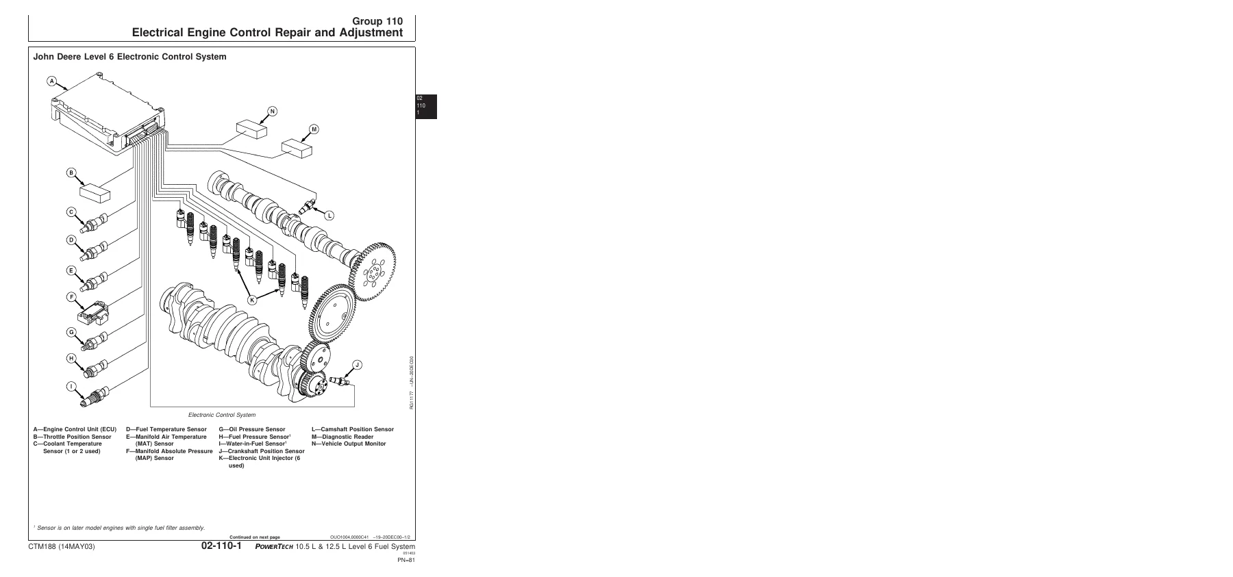
On the electrical side, Group 110 walks through removal and installation of the coolant temperature sensor, fuel temperature sensor (dual and single rail versions), fuel pressure sensor, water-in-fuel sensor, oil pressure sensor, manifold air temperature sensor, manifold absolute pressure sensor, camshaft position sensor and crankshaft position sensor. It also covers electrical insulating compound application, high-pressure washer precautions, and repair procedures for WEATHERPACK, METRI-PACK (pull and push type), DEUTSCH and CINCH connectors, including terminal extraction and crimping.

Theory of operation groups explain the low pressure dual rail and single rail fuel supply systems, and step through the EUI fill, vent, pumping and injection cycles on each rail system, along with the electrical control system overview, sensor measurement principles for temperature and pressure, throttle position methods (analog, CAN, dual state, tri-state, ramp, PWM, multi-state and excavator), engine speed and piston position determination, ECU self-diagnosis, and CAN bus communication.

The diagnostics groups are structured around observable symptoms and diagnostic trouble codes. The symptom charts include E1 engine cranks/won’t start, E2 engine misfires/runs irregularly, E3 engine does not develop full power, E4 excessive white exhaust smoke, E5 excessive black or gray exhaust smoke, E6 engine will not crank, E7 engine idles poorly, E8 abnormal engine noise, F1 dual rail fuel supply system check, F2 excessive fuel consumption on a dual rail system, F3 fuel in oil on a dual rail system, F4 single rail fuel supply system check, F5 excessive fuel consumption on a single rail system, F6 fuel in oil on a single rail system, and D1/D2 ECU communication diagnostics. The DTC section lists SPN/FMI codes and 2-digit equivalents with diagnostic procedures for throttle, fuel supply pressure, water-in-fuel, oil pressure, manifold air pressure and temperature, air filter restriction, engine coolant temperature and level, ECU power down, fuel temperature, injector wiring, sensor supply voltage, injector supply voltage, ECU error, cam and crank position, CAN error, and cylinder #1 through #6 EUI circuit open and shorted codes.

There is also a full engine test instruction set covering cylinder misfire, compression and cylinder cutout testing, and the ECU reprogramming procedure with the Diagnostic Scan Tool or SERVICE ADVISOR, including payload file download steps.

Engine Applications Covered

The Engine Application Chart in Group 001 lists John Deere agricultural and construction equipment applications for the 6105 and 6125 family, including 4-wheel drive tractors (9200, 9300, 9400, 9220, 9320, 9420, 9520), LTV track tractors (9300T, 9400T, 9320T, 9420T, 9520T), combines (9750 STS, 9750 STS CS, 9880), self-propelled forage harvesters (6750, 6850, 7300, 7400, 7500), the CAMECO CH2500 cane harvester, loaders (744H, 744HM/H Log Loader, 824H, 844H) and excavators (230 LC, 450C LC). OEM and marine engine models are also listed.

Why This Manual Matters

Fuel systems on these engines are sensitive to cleanliness, correct torques and correct procedures, and the electronic control side depends on accurate sensor input and clean injector circuits. Guessing at preload, torque values, oil-ring face seal tightening, or wiring connectors is how a small fault becomes a large repair bill. Having the exact CTM188 fuel system and Level 6 electronic control procedures in front of you makes the job repeatable: you know what to disconnect, what to cap, what to torque-turn, and what the diagnostic chart wants you to check next.

Whether you are chasing a low fuel supply pressure code, replacing injector O-rings, flushing a fuel rail, chasing an intermittent crank or cam sensor fault, or working through a throttle voltage or EUI circuit DTC, the John Deere PowerTech 10.5L 12.5L Level 6 Lucas EUI fuel systems CTM188 manual gives you the sequence the factory expects.

IMAGES PREVIEW

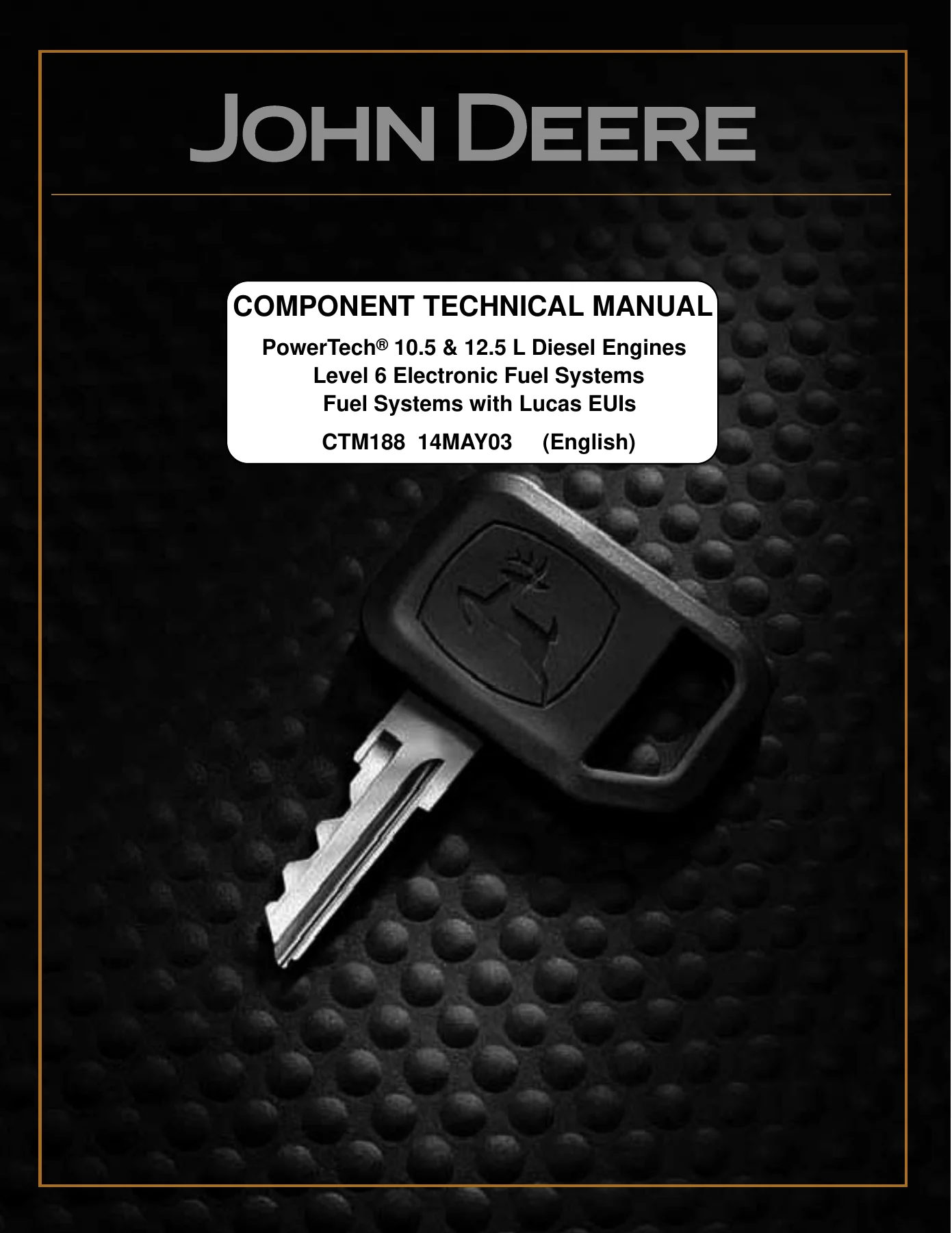
John Deere PowerTech 10.5L 12.5L Level 6 Lucas EUI Fuel Systems CTM188 Component Technical Manual β€” PDF page 1 preview
John Deere PowerTech 10.5L 12.5L Level 6 Lucas EUI Fuel Systems CTM188 Component Technical Manual β€” PDF page 34 preview
John Deere PowerTech 10.5L 12.5L Level 6 Lucas EUI Fuel Systems CTM188 Component Technical Manual β€” PDF page 82 preview

Instant PDF Delivery

This CTM188 John Deere fuel systems manual is delivered as an instant PDF download after payment. There is no shipping and no waiting. You can view it on a laptop, tablet or phone, print the pages you need for the shop, and keep the file with the machine records. If you service PowerTech 10.5 L or 12.5 L engines with Level 6 electronic fuel control and Lucas EUIs, this is the fuel system and electrical control reference to keep on hand.
Reviews

There are no reviews yet.

Be the first to review “John Deere PowerTech 10.5L 12.5L Level 6 Lucas EUI Fuel Systems CTM188 Component Technical Manual”

What Our Customers Say

β˜…β˜…β˜…β˜…β˜… Live reviews from customers
Loading customer reviews...
0
    0
    Your Cart
    Your cart is emptyReturn to Shop
    πŸ›’
    Recently Purchased
    πŸ•’ verified order