
Kawasaki 115ZV Wheel Loader Parts Catalog 93316-00106 – PDF Parts Manual Download
Original price was: $73.95.$45.95Current price is: $45.95.
Complete Kawasaki 115ZV wheel loader parts catalog, document 93316-00106, covering every major assembly from chassis to cab. 830-page illustrated PDF with exploded views, part numbers, quantities and chassis serial ranges.
Description
File Details
- Manual type: Illustrated Parts Catalog
- Brand: Kawasaki
- Machine: 115ZV Wheel Loader
- Document number: 93316-00106
- Publication date: November 2008
- Language: English
- Page count: 830
- File format: PDF
Chapters Covered
- Chassis and Electrical System
- Power System
- Torque Converter and Transmission System
- Axle and Differential
- Brake System
- Control System
- Loading Hydraulic System
- Bucket, Accessories, etc.
- Cab
- Option
- Hot Slag Spec.
- Cold Handling Spec.
Chassis and Electrical System
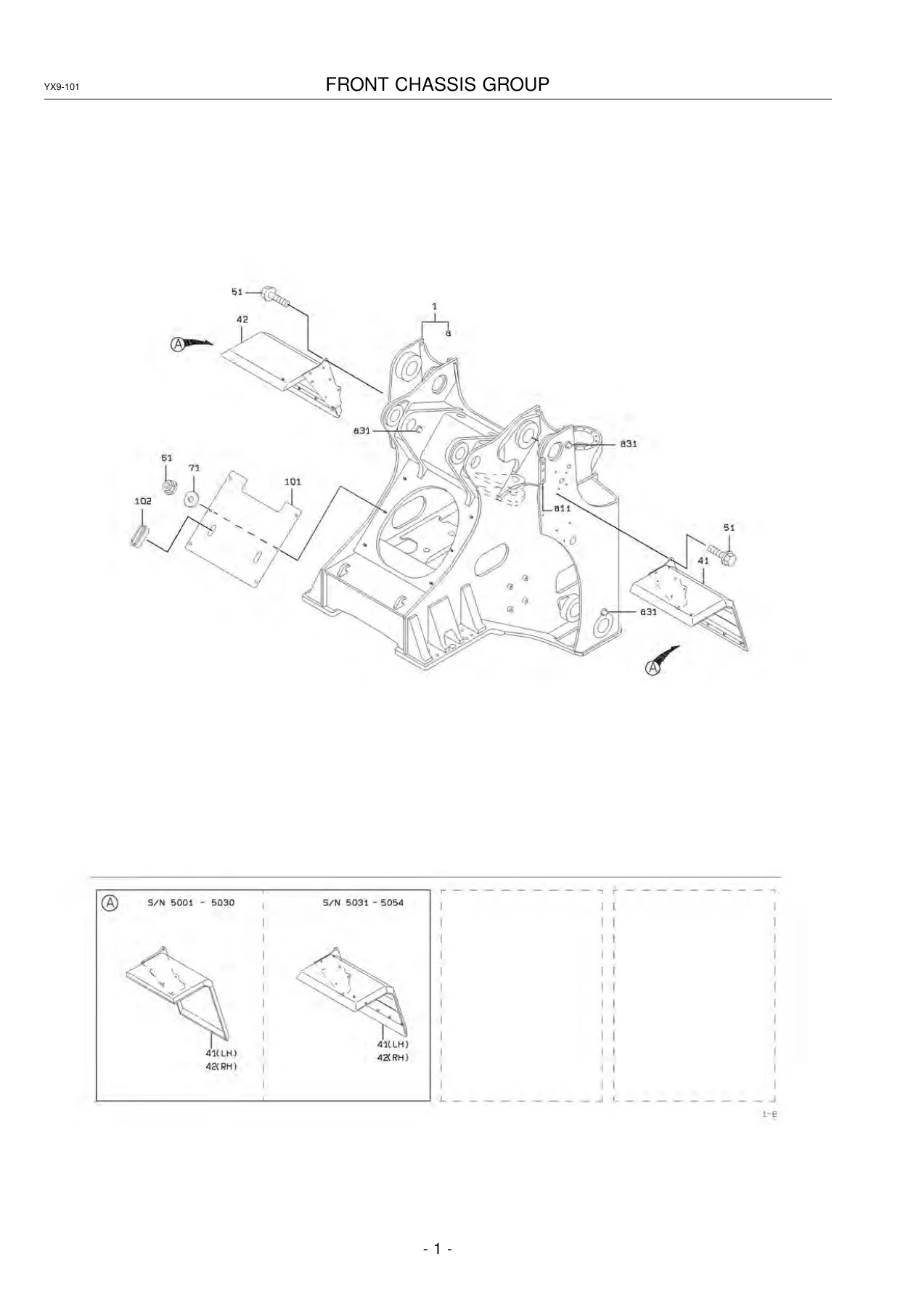
Everything that bolts to the 115ZV front and rear chassis frames sits in this opening section: the front chassis itself, lift arm, pin mount, centre pin, fuel and oil tanks, floor boards, seat stand and control box mounts, deck and fender panels, handrails, steps, screen boards, engine room covers, radiator guard, rear grille, wind shield, cover mounts, seat group, seat, suspension and grease piping. The electrical side covers the gauge group, electrical parts mounts, lamp groups, battery and grease gun mounts, relay and switch mounts, plus the complete front chassis, rear chassis and floor board wiring harnesses and handrail mounts.
Power System
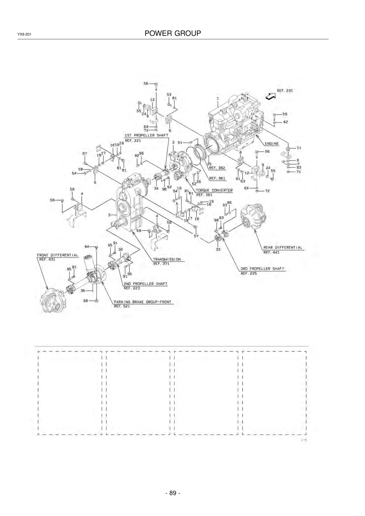
The power group section maps the 115ZV driveline from the engine back through the drain line, first, second and third propeller shafts, radiator group and radiator cores, oil motor, water line, air cooler line, air cleaner group, exhaust group and fuel line. Every hose, clamp, flange and pipe fitting is called out with its own part number, unit quantity and applicable serial range so the correct piece arrives the first time.
Torque Converter and Transmission System
A deep section covering the transmission hydraulic lines, torque converter, T/C input shaft group, gear shaft and oil pump group, the transmission housing, input shaft group, high and reverse clutch, first clutch, low / second / third clutch, idle shaft group, output shaft group, solenoid valve and valve unit, and the transmission repair kit listings. Friction discs, separation discs, pistons, spiders, planet gears, snap rings and seals are broken down to component level with individual part numbers.
Axle and Differential
Front and rear axle groups, axle support groups, the front and rear differential assemblies, and the tyre and wheel group. Bearings, bevel gears, spiral bevel gear sets, hubs, axle shafts, internal gears, ring wear rings, brake discs, pistons, springs and wheel rims are all itemised, with serial break points that flag which revision applies to which chassis number.
Brake System
Brake lines for the front chassis, floor board, rear chassis, axle and accumulator, followed by the parking brake group, brake valve group, check valve, brake valve assemblies, oil cylinder, unloader valve and parking brake itself. Every seal kit, spring, plunger, poppet and adjustor is listed with quantity, and the brake line section names the exact pipe assemblies and hose part numbers for each leg of the circuit.
Control System
Valve control groups, steering cylinder group, steering valve, steering cylinder, bucket positioner group, kickout group, control lever groups and the steering pilot valve. The section includes exploded views of the control levers, linkage, bearing needles, seals and boots, plus the ball joints, rods, arms and knobs that make up the full lever assembly. Both the early and later lever configurations are covered with their own serial ranges.
Loading Hydraulic System
Loading hydraulic lines for the front chassis, rear chassis, steering cylinder, centre pin and oil cooler, plus fan motor hydraulic lines, pilot hydraulic lines, the double oil pump, accumulator, control valve, pilot valve, valve group, fan motor valve, lift cylinder, tilt cylinder and the fitting mount section. Flange halves, O-rings, split flanges, bolts and adapters are all listed for each connection, so hydraulic repairs can be planned end to end.
Bucket, Accessories, etc.
Bucket assemblies for general purpose, rock-RS and rock-RV duty, the marking group, cap mount, lock group and repair and maintenance parts. Bucket edges, side edges, side bits, wear plates, bushings and weld-on plates are itemised so a bucket can be rebuilt or re-edged with the correct Kawasaki part numbers.
Cab
The cab mount, cab structure, door group, front wiper and window washer group, electrical parts group, cab wiring, mirror group, rear wiper and window washer group, cab accessories mount, fan assembly, ROPS mount, cab cover group, floor board air duct group, damper assembly, air conditioner mounts, air conditioner cover group, air conditioner line, condenser and cover mount, compressor mount and the air conditioner unit. Interior trim, seals, hinges, locks, regulators, glass and handles are all broken down.
Option Sections
Optional equipment is grouped into dedicated sections: rear large fenders, belly guard, steel plate rear grille, high lift arm specification (lift arm, tilt cylinder, hydraulic line and cable mount), reversing fan (fan motor hydraulic line, relief valve mount, motor mount, fan motor and electrical equipment mount), easy-cleaning radiator mount, dust-proof radiator mount, three-way piping, single lever valve control, hydraulic single lever valve control, ride control, emergency steering group, steering wheel mount, shift lever group, tilt case group, orbitrol, operation stand, seat mount, multi control valve, two-step relief valve, dust-proof covers and sponge mounts, battery cut-off switch and four-way flasher group.
Hot Slag and Cold Handling Specifications
Two further specification sections appear at the end of the catalog, listing the front chassis, fuel tank, oil tank, lift arm, pin mount, rear chassis, control box cover, deck and fender, radiator guard, cover mount, grease piping, transmission hydraulic line, three-way piping, control valve, pilot valve, front and rear axle, bucket positioner and loading hydraulic line parts unique to those builds.
How the 115ZV Parts Catalog Is Organised
Each section opens with an exploded-view illustration that carries balloon symbols keyed to a part list on the following pages. The list gives the symbol, the part number, the part name, the unit quantity, the applicable chassis or serial range and any relevant remarks. Assembly parts, kit parts and interchangeability notes are flagged directly in the remarks column, so you can see at a glance whether a component is sold individually or only as part of an assembly. For chassis-specific parts, the serial (A) and serial (B) columns tell you exactly where a part begins and ends in production. The front matter also explains how to read the illustrations, how to use the parts lists, how to interpret interchangeability codes (A, B, C) and how to handle shims and A/R quantities.
Why This 115ZV Catalog Matters in the Workshop
Ordering the wrong part for a wheel loader is expensive and slow. This catalog removes the guesswork by tying every component to the exact chassis number range it was fitted to. Whether you are rebuilding a front axle, chasing a hydraulic leak in the loading circuit, replacing a clutch pack inside the transmission, re-sealing the tilt cylinder, replacing a brake valve or sourcing a door hinge for the cab, the exploded views and part tables give you the correct part number, quantity and applicable serial range on one page. Independent workshops, fleet maintenance teams and parts departments can quote, cross-check and order without a round trip to the dealer.
Get the Complete 115ZV Parts Catalog as an Instant PDF
This is the full Kawasaki 115ZV wheel loader parts catalogue 93316-00106, delivered as a printable PDF. No shipping, no waiting for a disc in the post. The file downloads immediately after checkout and opens on any laptop, tablet or phone. Print the exploded views you need for the job, mark up part numbers in the workshop and keep the index on hand for the next rebuild. One purchase, unlimited access to every section of the manual, from the front chassis group right through to the air conditioner unit and the cold handling specification.
IMAGES PREVIEW
Reviews
There are no reviews yet.