
Kobelco SK230SRLC-3 Hydraulic Excavator Shop Manual S5YB0018E02 (2017)
Original price was: $39.95.$24.95Current price is: $24.95.
Shop manual for the Kobelco SK230SRLC-3 hydraulic excavator (serial LA07-03001~) covering specifications, maintenance tests, mechatro and hydraulic systems, electric harnesses, disassembly of upper structure and travel gear, troubleshooting by error code and symptom, and the HINO J05E-TJ engine section. Book code S5YB0018E02, English, 1544 pages.
Description
Kobelco SK230SRLC-3 Hydraulic Excavator Shop Manual S5YB0018E02 (2017)
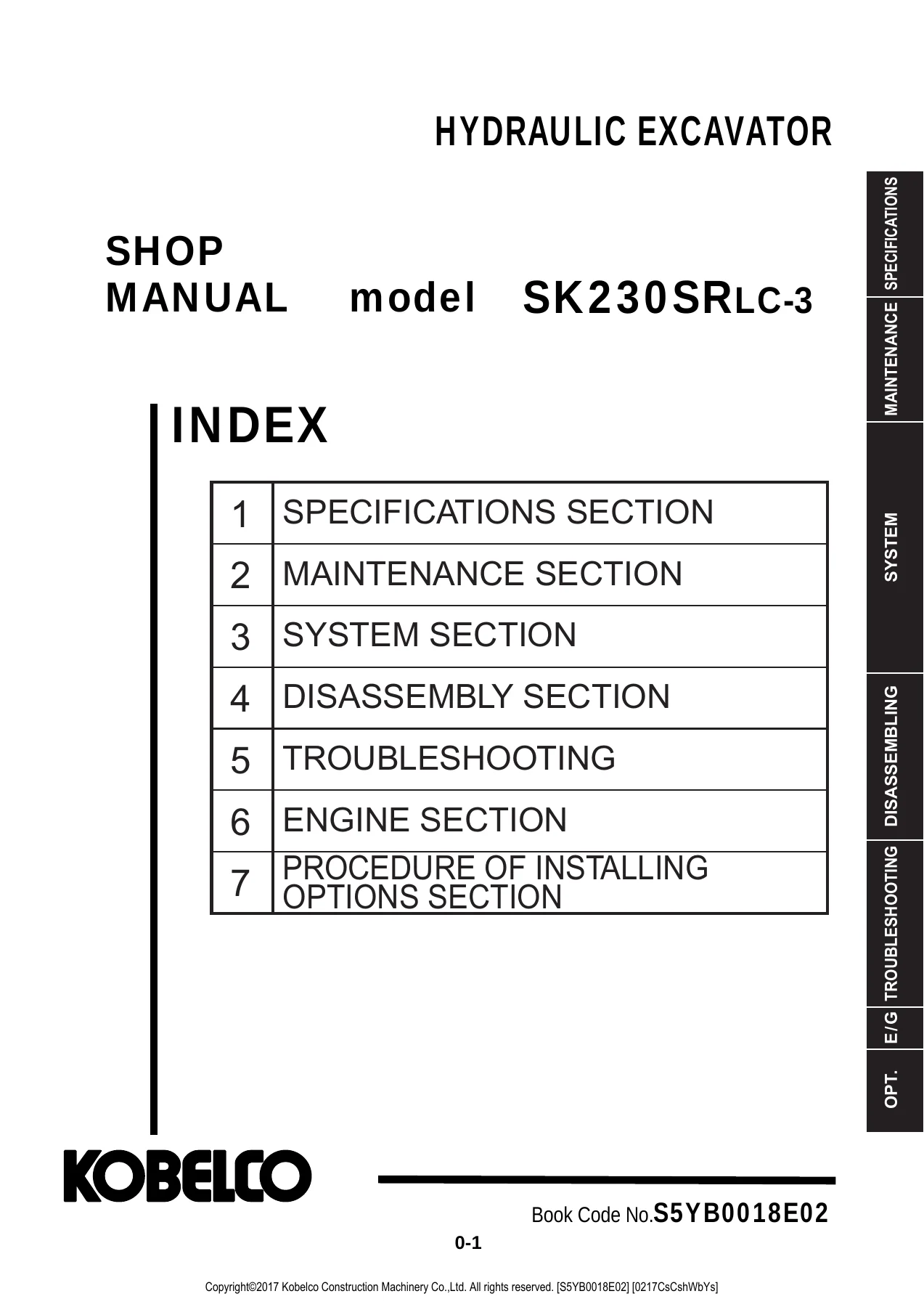
This Kobelco SK230SRLC-3 Hydraulic Excavator Shop Manual S5YB0018E02 (2017) gathers the repair, adjustment, and inspection material needed to service the short-radius SK230SRLC-3 crawler excavator. The compiled book is identified on the cover as Book Code No. S5YB0018E02 and is written for machines in the LA07-03001~ serial range. Individual bound sections inside carry their own book codes and first-edition dates (most November 2013 for the EUR compilation), while the engine chapter is the October 2016 S5YN5146E02 Hino-based service text. Use it on the bench when you need component weights before a lift, relief-valve test points, harness layouts, cylinder rebuild steps, or error-code paths on the mechatro controller.
File Details
- Manual type: Shop manual (repair, maintenance, and adjustment)
- Brand / model: Kobelco SK230SRLC-3 hydraulic excavator
- Language: English
- Page count: 1544
- File format: PDF
- Document number: S5YB0018E02
- Applicable machines: LA07-03001~
- Compilation year shown on cover: 2017
Machine Covered in This Shop Manual
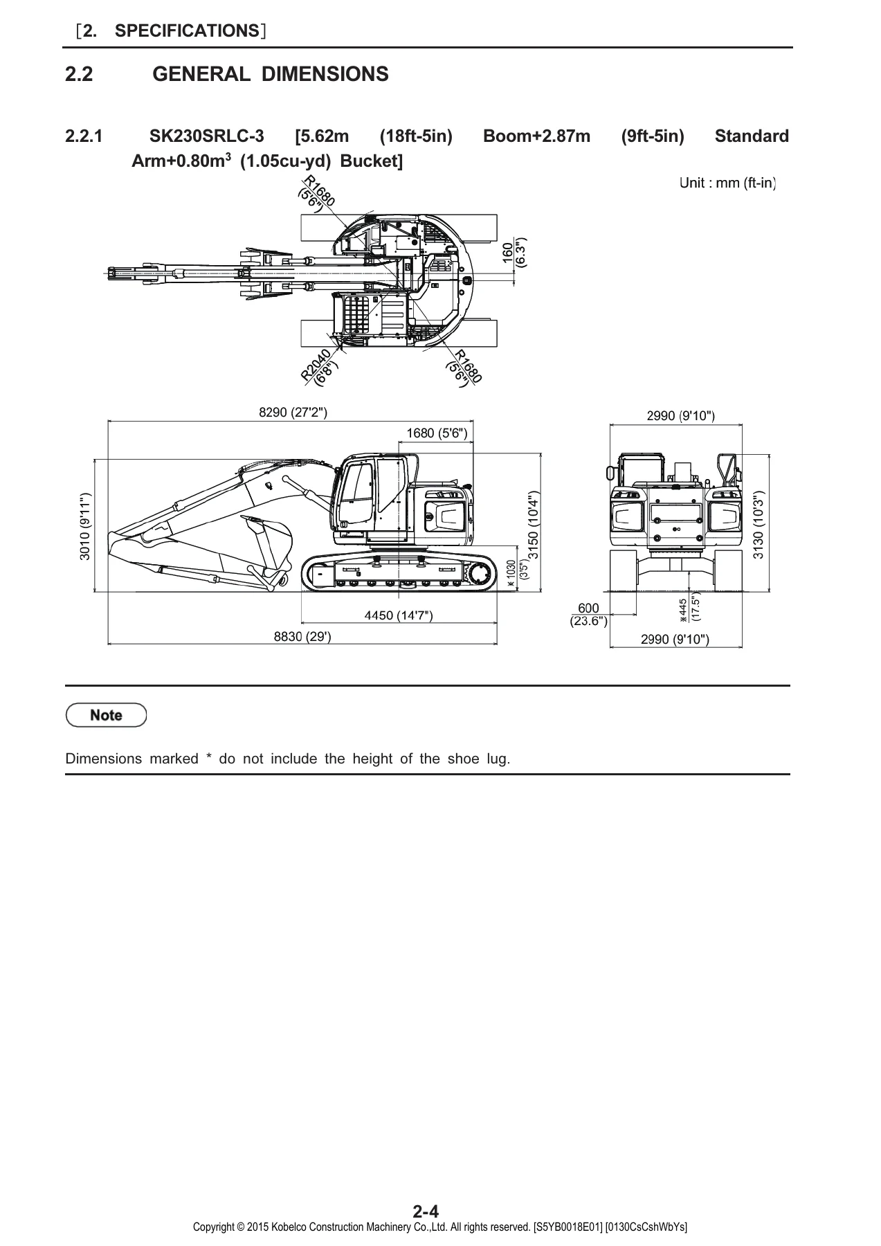
The specifications chapter names the complete machine as the SK230SRLC-3 with the standard front of a 5.62 m (18 ft-5 in) boom, 2.87 m (9 ft-5 in) arm, and 0.80 m³ (1.05 cu-yd) hoe bucket. Fully equipped weight is given as 22,900 kg (50,500 lbs). Upper structure assembly is listed at 12,000 kg (26,460 lbs), lower machinery with 600 mm grouser shoes at 7,250 kg (15,990 lbs), and the standard attachment group at 3,650 kg (8,048 lbs). Those figures matter when slinging the counterweight (6,150 kg / 13,560 lbs), cab, pump, or track assemblies.
Travel is specified at 3.6 / 6.0 km/h (2.2 / 3.7 mile/h) for 1-speed / 2-speed, swing at 13.3 min⁻¹ (13.3 rpm), and gradeability at 70% (35 degrees). Grouser shoes of 600 mm, 700 mm, and 800 mm are tabulated with overall crawler widths and ground pressures. Hoe buckets from 0.51 m³ through 0.93 m³ heaped capacity are listed against the standard arm, with breaker and nibbler noted as available combinations. The power unit is the water-cooled, four-cycle, four-cylinder HINO J05E-TJ direct-injection diesel with intercooler turbocharger: 4 × 112 mm bore × 130 mm stroke, 5,123 cc (312.61 cu-in), compression ratio 17.0, rated output 124 kW (169 PS) at 2,000 min⁻¹, maximum torque 660 N·m (487 lbf-ft) at 1,600 min⁻¹. Electrical supply on the machine side is 24 V with a 5.0 kW starter and 60 A alternator.
Chapters Covered
- 1. Outline — general precautions for repairs; preparation before disassembling; safety when disassembling and assembling; hydraulic equipment handling; electrical equipment; hydraulic parts; weld repair; environmental issues; SI unit system
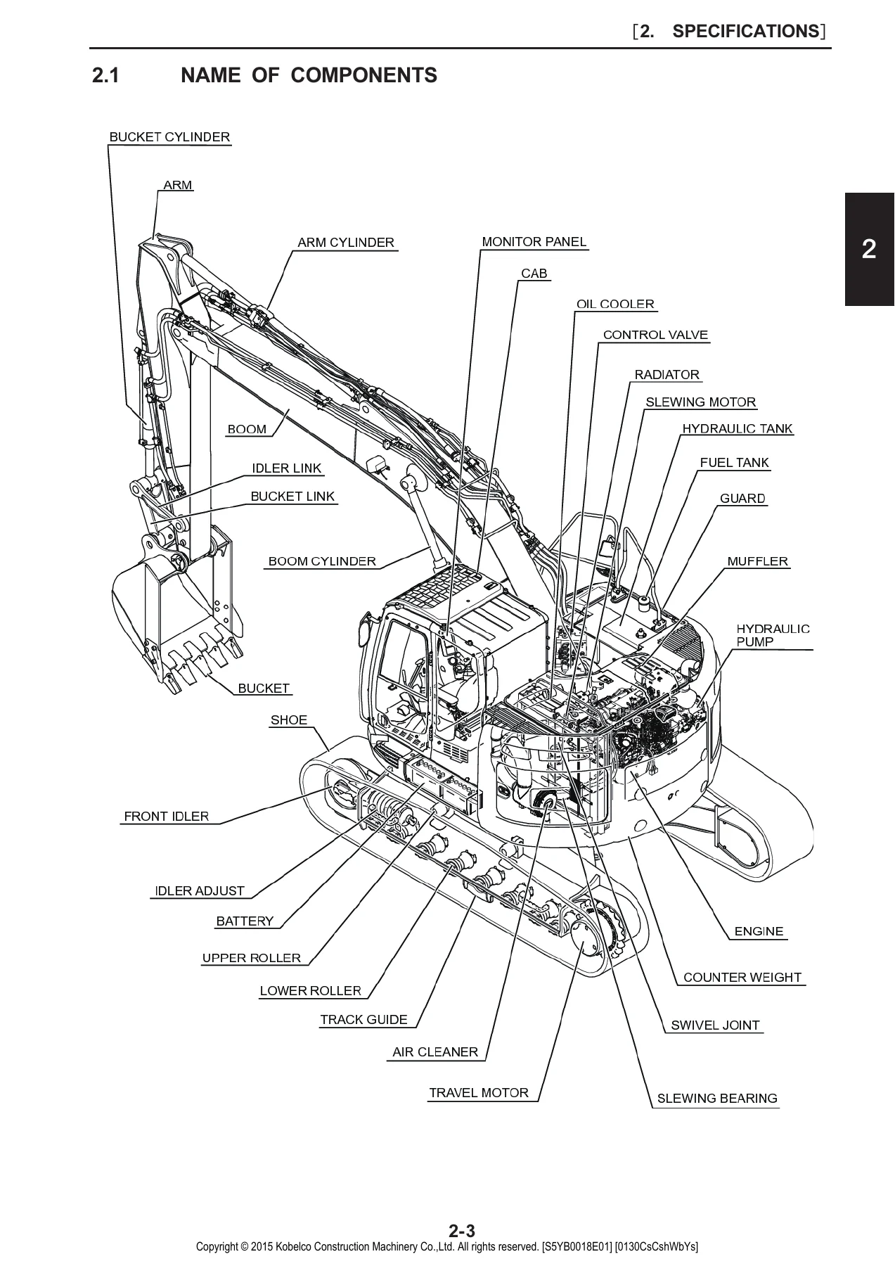
- 2. Specifications — name of components; general dimensions; weight of components; transportation dimensions; speed and climbing capability; engine and hydraulic component lists; crawler and bucket types; attachment combinations; HINO J05E-TJ engine specification and characteristic curve
- 3. Attachment dimensions — boom, arm, and bucket dimensional drawings and maintenance standards; lug and boss section drawings
- 11. Tools — tightening torques for capscrews, nuts, hoses, fittings, plugs; special tools; locking and sealing compounds; suction stopper; counterweight, upper-frame, engine-mount, and track-spring jigs
- 12. Standard maintenance time table — excavator working-time table; engine maintenance service standard time list
- 13. Maintenance standard and test procedure — performance inspection standard table; engine-speed measurement; hydraulic-pressure measurement and relief-valve adjustment; travel, swing, attachment, and swing-bearing performance tests; mechatro controller input/output and B-C adjustment; diesel particulate filter (DPF) handling, automatic and manual regeneration, inspection and precautions
- 21. Mechatro control system — unload valve, positive / P-Q, boom-up conflux, arm recirculation and anti-cavitation, bucket conflux, swing priority, travel-straight, and pressure-release controls; optional N&B and option-conflux functions; multi display, self diagnosis, service diagnosis, trouble history, and maintenance-schedule setting
- 22. Hydraulic system — circuits and components; color coding; neutral, travel, bucket, boom, swing, arm, combined, and pressure-draining circuits
- 23. Electric system — electric circuit diagram; electrical equipment; harness list and layouts (instrument panel, controller, operator controls, upper and cab harnesses, rear camera, extra / overload / proportional-hand / opt-relief circuits, boom lights, angle sensor, fuel pump, seat)
- 24. Components system — hydraulic pump-regulator, control valve, attachment and travel pilot valves, swing motor unit, travel motor, swivel joint, cylinders; electrical equipment list and specifications
- 25. Air-conditioner system — HVAC air cycle and auto system outline; components, piping, cooling-circuit function; unit disassembly; refrigerant charging; electric circuit; troubleshooting and self-diagnosis
- 31. Disassembling and assembling — chapter format and tightening-torque indication
- 32. Attachments — removing and installing attachment assembly, bucket, arm, and boom; cylinder disassembly and assembly
- 33. Upper slewing structure — removing and installing operator seat, cab, battery, guards, under cover, fuel tank, hydraulic tank, hydraulic pump, air cleaner, muffler, counterweight, radiator and oil cooler, engine, console cover, control valve, pilot valves, swing motor, swivel joint, and upper frame; shop disassembly of pump-regulator, control valve, pilot valves, swing motor, and swivel joint
- 34. Travel system — crawler, upper and lower rollers, front idler / adjuster, sprocket, travel motor, swing bearing; travel-motor unit construction, tools, disassembly, maintenance standard, and troubleshooting
- 46. Troubleshooting by error codes — on-site judgment; failure classification; mechatro-controller blown fuse; error-code troubleshooting
- 47. Troubleshooting by trouble — hydraulic system; electric systems and wiring checks; engine-related troubleshooting
- 48. Trouble diagnosis mode — referenced from the compiled index for controller diagnosis work
- 51. Engine — HINO MOTORS-based service text for the single engine (Book Code S5YN5146E02), with a preface that operator-manual replacement intervals take precedence where they differ
IMAGES PREVIEW
Taken together, the chapters move from identity and lifting data through scheduled tests, electronic and hydraulic theory, then into actual removal, rebuild, and fault-finding. A technician can stay inside one book from a pressure-gauge hook-up on the main circuit to a full travel-motor strip-down or a DPF regeneration check.
Inspection, Adjustment, and Performance Tests
Chapter 13 is the shop-floor measuring section of the Kobelco SK230SRLC-3 Hydraulic Excavator Shop Manual S5YB0018E02 (2017). It sets cleanliness of hydraulic oil in the tank at NAS 9 or less and a tank-surface oil temperature of 50 °C (122 °F) with a ±5 °C window for standard measuring conditions. Gauge ports are identified for the main circuit after tank pressure is released. Relief-valve adjustment is written as a sequenced procedure rather than a single set-screw note.
Travel tests cover speed, deviation, parking-brake holding, and travel-motor drain rate with oil at 45 to 55 °C (113 to 131 °F). Swing tests cover swing time, swing-brake and swing-parking-brake performance, and swing-motor drain. Attachment tests time the boom, arm, and bucket cylinders and check rod drift for oil tightness. Swing-bearing play is measured as its own item. Mechatro work includes engine-control input/output, B-C output adjustment, and the fallback actions when controller equipment has failed. DPF coverage explains automatic versus manual regeneration, inspection points, maintenance standard, and operating precautions.
Hydraulic, Electric, and Cab Systems
The hydraulic plant is described as two variable-displacement axial piston pumps plus one gear pump, an axial-piston swing motor, two variable-displacement axial-piston travel motors with counterbalance valves, an 8-spool control valve, double-acting boom/arm/bucket cylinders, and an air-cooled oil cooler. Circuit pages walk the oil path in neutral and then through travel, bucket, boom, swing, arm, and combined functions, including the pressure-draining (releasing) circuit used before hoses come off. Component pages add regulator, pilot-valve, swivel-joint, and cylinder construction so a rebuild is not guesswork from the circuit sheet alone.
Electric coverage starts with the circuit diagram and then maps harness assemblies across the upper structure, floor plate, cab, boom, camera, lights, angle sensor, and optional extra / overload-alarm / proportional-hand-control / option-relief circuits. Connector handling rules in the outline chapter are explicit: key off before disconnecting, never pull on the wire, dry a waterproof connector completely before reconnection, and isolate the battery ground before working near the battery or battery relay.
The HVAC chapter treats the auto air-conditioner as a complete system: air cycle, component layout, piping and air-dryer assembly, cooling-circuit function, unit disassembly, refrigerant charging steps, wiring and connectors, symptom troubleshooting, and self-diagnosis.
Disassembly Weights and Shop Practice
Outline and specifications sections keep repeating the same practical point: know the mass before the hoist goes on. Examples printed in the weight table include engine dry weight marked at 560 kg (1,235 lbs) in the upper-frame breakdown and 572 kg (1,261 lbs) in the detailed engine specification; hydraulic oil tank about 160 kg dry; fuel tank about 150 kg; control valve about 250 kg; pump about 140 kg; each boom cylinder about 200 kg; each travel motor about 280 kg; each 600 mm track-link-with-shoes assembly 1,330 kg. Hydraulic oil in the lubricants table is 200 kg (440 lbs), engine oil 20 kg, fuel 270 kg, water 20 kg.
Hydraulic-equipment rules are equally concrete. Release tank pressure or open the return-side cover and pull the filter before cracking lines. Cap every open port. Replace O-rings, back-up rings, and oil seals. Bleed the pump and swing motor at the upper drain plug during low idle until oil appears; run travel motors and cylinders at no-load low speed for 10 minutes or more; do not stroke a freshly installed cylinder to the end on the first cycle. After any oil or suction-side work, set the attachment in the hydraulic-oil check position and refill to the level-gauge marks.
Fault Finding
Error-code troubleshooting opens with on-site judgment and failure classification, then treats a blown mechatro-controller fuse as its own case before walking individual codes. Symptom troubleshooting splits hydraulic faults, electric faults with a wiring-check procedure, and engine-related faults. Travel-motor and air-conditioner chapters add local trouble charts (external and internal oil leaks at the swivel, two-speed changeover issues, HVAC self-diagnosis). The compiled index also points to trouble diagnosis mode on the controller so stored history and service screens from chapter 21 can be used with the code charts rather than in isolation.
Engine Section Note
Chapter 51 states that the engine text is edited from the HINO MOTOR service manual without modification and that replacement intervals printed in the operator’s manual are the ones to follow when the two books disagree. An example given is a DPF hose interval listed as three years in the shop-manual exhaust section versus two years in the operator’s manual. Keep both documents in the shop when planning DPF or hose work on the J05E-TJ.
Use This Manual on the Machine
With the Kobelco SK230SRLC-3 Hydraulic Excavator Shop Manual S5YB0018E02 (2017) you can weigh and lift major assemblies safely, measure and set hydraulic pressures, time travel and swing, rebuild attachment cylinders, strip the 8-spool valve or piston pumps, change rollers and idlers, trace a cab or boom harness, charge the HVAC system, read mechatro error codes, and service the HINO J05E-TJ using the included engine chapter. Correct test temperatures, drain procedures, and torque tables keep a short-radius 23-tonne class excavator from leaving the shop with a missed air-bleed or an underspec fastener.
Download is instant after purchase. Open the PDF on a shop computer, tablet, or phone and print the pages you need for the job in front of you. No shipping wait and no extra hardware required.



Reviews
There are no reviews yet.