
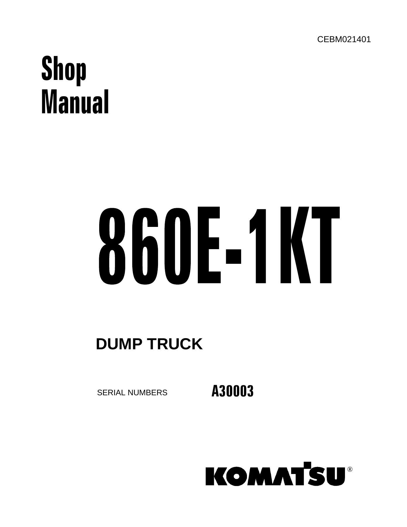
Komatsu 860E-1KT Dump Truck Shop Manual CEBM021401 – PDF Service & Repair Guide
Original price was: $79.95.$49.95Current price is: $49.95.
Complete Komatsu 860E-1KT dump truck shop manual (CEBM021401) for serial A30003 and up. Covers engine, AC drive, SIBAS 32, hydraulics, brakes, steering, hoist, suspensions, troubleshooting and full disassembly/assembly procedures in a single downloadable PDF.
Description
Komatsu 860E-1KT Dump Truck Shop Manual — Complete PDF Service & Repair Guide
This is the Komatsu 860E-1KT Dump Truck Shop Manual, form number CEBM021401, covering serial numbers A30003 and up. It is the full workshop-level service publication used to diagnose, test, adjust, disassemble, repair and reassemble the 860E-1KT electric drive haul truck. Everything from the diesel engine and AC drive system to the wet disc brakes, hydro-pneumatic suspensions and hydraulic hoist circuit is documented inside a single, complete PDF. If you maintain, repair or rebuild an 860E-1KT, this is the reference that tells you how the truck is built, what the correct values are, and exactly how each job is done.
File Details
- Manual type: Shop Manual (service, repair, troubleshooting and disassembly)
- Brand: Komatsu
- Model: 860E-1KT Dump Truck (also applies to 860E-1K)
- Serial numbers: A30003 and up
- Form / document number: CEBM021401
- Language: English
- Format: PDF (downloadable, printable, viewable on any device)
- Publisher: Komatsu America Corp. / Komatsu Ltd.
- Publication date: 2009
- Contents: Specification, structure & function, standard values, testing & adjusting, troubleshooting, disassembly & assembly, hydraulic & electrical diagrams
Chapters Covered
- 00 Index and foreword
- 01 Specification
- 10 Structure, function and maintenance standard
- 20 Standard value table
- 30 Testing and adjusting
- 40 Troubleshooting
- 50 Disassembly and assembly
- 90 Diagrams and drawings
01 Specification
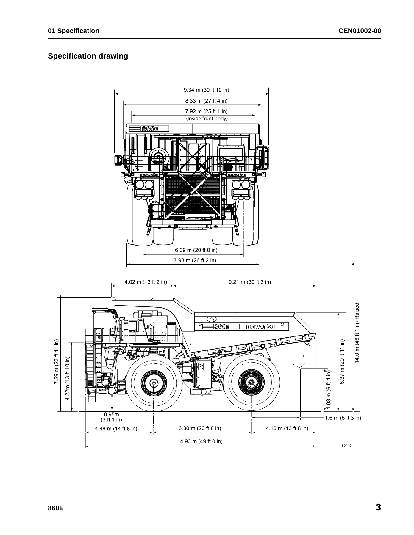
Contains the specification drawing, full truck specifications, the weight table, and the fuel, coolant and lubricant charts. This is where you find the factory ratings for the 860E-1KT — dimensions, dump body capacity, travel speeds, gradeability, engine model and output, motorized wheel data, tire size and pressures, and the approved fluids for every reservoir including engine oil, hydraulic oil, suspension oil, gear lube and coolant. Anti-freeze mixing ratios and suspension cylinder nitrogen specifications are also listed.
10 Structure, Function and Maintenance Standard
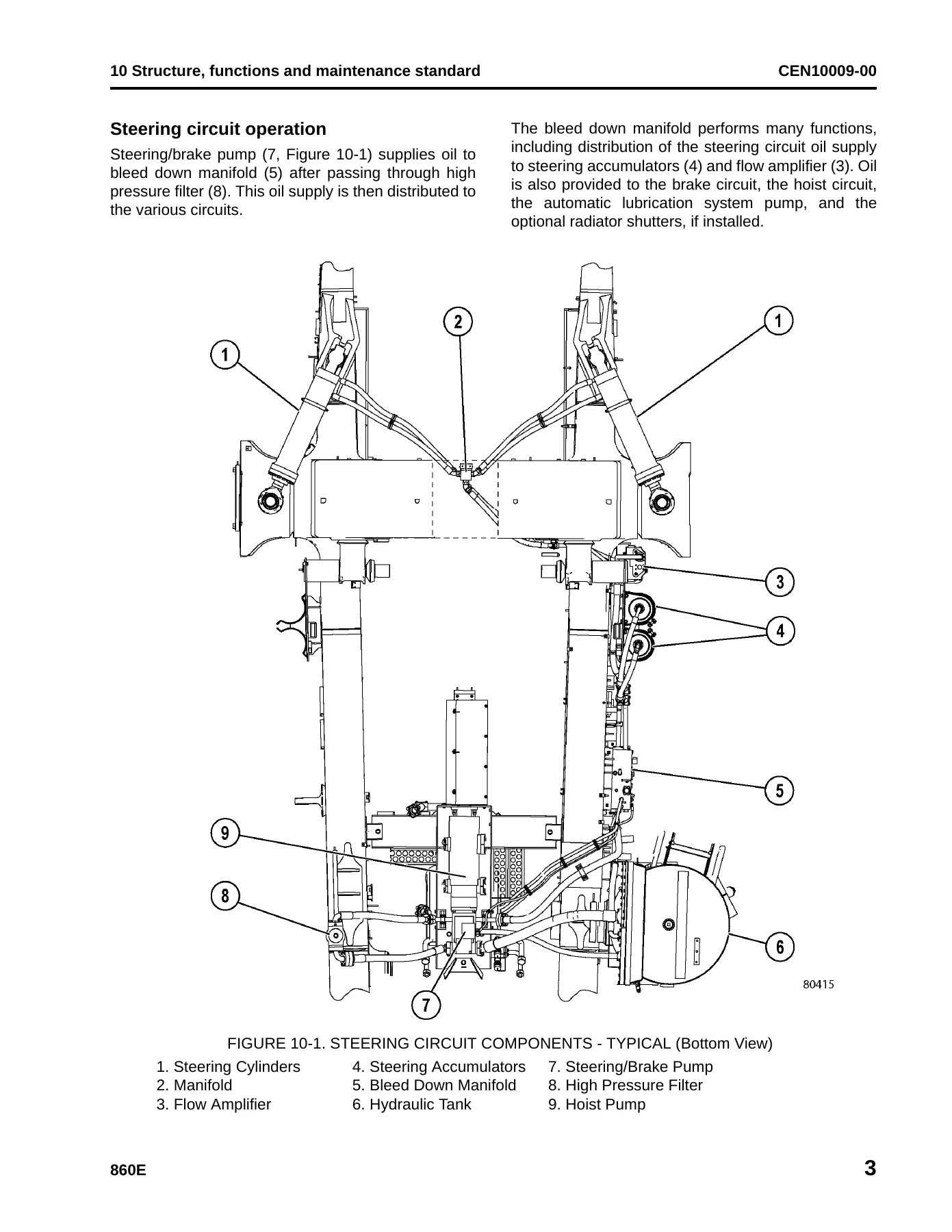
This is the largest technical chapter and explains how each major system on the 860E-1KT works, with wear limits and maintenance standards built in. It covers cab air conditioning principles and components; the steering circuit including the flow amplifier, steering control unit, accumulators and bleed down manifold; the hoist circuit and hoist pilot valve; the service, secondary, parking and brake lock circuits; front and rear hydro-pneumatic suspensions; the 24V electrical system and battery supply; the interface module (IM); and the entire AC drive system including the SR rectifier module, ST auxiliary inverter, SD phase modules, gate unit power supplies, DC link components, contactors, coolant system, main alternator, IGBT modules and grid box. The SIBAS 32 traction control unit is documented card-by-card, including the CPU, DSP, I/O, TRACO, U/F, temperature sensor, UWS, digital input, power start-up and power supply cards. Wheel motor transmission and reserve engine oil system coverage is also included, along with wear data tables throughout.
20 Standard Value Table
Provides the standard value and permissible value table for the truck. Use this chapter to check a new machine against an in-service machine. It lists travel speeds, engine speeds, steering effort, pedal forces and strokes, suspension cylinder installed lengths and nitrogen pressures, accumulator precharge pressures, brake release and operating pressures, tire pressures, relief pressures, hoist lift and lower times, and other judgement criteria used during testing and troubleshooting.
30 Testing and Adjusting
Explains the special tools and the procedures for testing and adjusting each system. It includes the special tool list, cab air conditioning servicing (leak detection, performance testing, oil checking, flushing, recovery, evacuation, charging and belt checkout), steering / brake cooling / hoist hydraulic system checkout, toe-in adjustment, brake circuit checkout and data sheets, brake piston leakage testing, wet disc and parking brake bleeding, brake valve and dual relay valve bench testing, accumulator charging and storage, accumulator leak testing, suspension oiling and charging, payload meter initial setting, interface module software and checkout, SIBAS user procedures and software loading, ZR/DSP software installation, and body position / hoist limit switch adjustment.
40 Troubleshooting
Divided by fault code and by system. It includes cab air conditioning troubleshooting, fuse and circuit breaker locations, and extensive fault code tables split into parts. The fault code sections cover suspension pressure sensors, incline sensor, payload meter faults, carryback and overload warnings, hydraulic filter and temperature faults, battery and charging faults, park brake and brake lock faults, steering and brake accumulator faults, interface module output overload faults, and the complete drive system fault code tables for SIBAS 32 systems — including DSP A / DSP B / DSP T events, I/O and UWS card events, CAN and serial link failures, trolley faults, temperature faults, current transducer faults, IGBT checkback faults and total block events. Electric motor troubleshooting is also provided.
50 Disassembly and Assembly
Step-by-step removal, installation, disassembly and assembly procedures for every major component group. It covers general information and special tools; cab air conditioning; wheels, spindles and rear axle; brake system including brake valve, dual relay valve, brake manifold and accumulators; steering system including steering control unit, flow amplifier, steering cylinders, steering/brake pump and accumulators; suspensions; hoist circuit including hoist pump, hoist valve, overcenter manifold, hoist pilot valve and hoist cylinders; operator cab; body and structures including dump body, body pads, decks, fuel tank and hydraulic tank; three-phase wheel motor; power module including alternator, engine, radiator and radiator repair; and auto lubrication system. Torque values and component weights are included where specified.
90 Diagrams and Drawings
Hydraulic and electrical circuit diagrams for the 860E-1KT, plus the drive system electrical schematics. Hydraulic coverage includes the steering, hoist and brake cooling circuit and the brake hydraulic circuit. Electrical coverage includes the 24V power distribution, brake warning circuits, lighting, wiper and window controls, key switch and shutdown delay, engine start and engine control, payload meter circuits, interface module wiring and sensor wiring, CAN network wiring, circuit and component locator sheets, oil reserve wiring, and the AC drive system schematics covering the rectifier bridge, DC link, inverters, choppers, motor circuits, auxiliary power and control, field regulator, gate unit power supply, TCU power, diagnostics panel and all SIBAS 32 circuit cards. Connector tables and arrangement drawings are also included. Trolley drive system schematics are provided for the 860E-1KT.
Systems and Components Documented in Detail
The 860E-1KT is a 200-ton-class electric drive haul truck, and this manual treats it as a complete machine rather than a single subsystem. You get the diesel engine side (KOMATSU SSDA16V160, 16-cylinder, 160 mm bore x 190 mm stroke, 60 L displacement, rated 2014 kW at 1,900 rpm), the AC drive and retarding system with the SIBAS 32 traction control unit, the wheel motor transmission, the hydraulic steering and brake circuits, the hoist circuit, the 24V electrical system, the hydro-pneumatic suspension cylinders, and the operator cab with its air conditioning, seating and controls. The drive system fault code tables alone run across seven dedicated parts, which makes this manual especially useful for diagnosing electrical and inverter faults on the AC drive truck rather than only mechanical problems.
Who This Komatsu 860E-1KT Shop Manual Is For
This PDF is written for the working technician, the shop foreman, the mine maintenance planner and the owner-operator who needs factory-level information on the 860E-1KT. It is the same class of publication that Komatsu distributors and trained service personnel use, organised so that a specific repair can be found quickly — specification in one section, testing and adjusting in another, fault codes in a third, and the actual disassembly and assembly sequence in a fourth. Whether you are replacing a wheel motor, bleeding the wet disc brakes, charging a suspension accumulator, loading SIBAS software, chasing a drive system event code, or checking a steering pressure, the procedure and the values are inside this manual.
Get the Complete Komatsu 860E-1KT Shop Manual as an Instant PDF
This listing is for the complete Komatsu 860E-1KT Dump Truck Shop Manual, form CEBM021401, delivered as a downloadable PDF. There is no physical book to ship and no waiting — the file is available immediately after checkout. You can read it on a laptop, tablet or phone in the workshop, print the pages you need for a job, and keep the full manual on file for future repairs. Having the correct specifications, torque values, fault code tables and step-by-step disassembly procedures on hand is what separates a repair done right from a repair done twice. Keep the Komatsu 860E-1KT shop manual within reach and every job on the truck — from routine testing and adjusting to a full component rebuild — starts from a known, factory-documented baseline.
IMAGES PREVIEW
Reviews
There are no reviews yet.