
Komatsu D275A-5 Crawler Dozer Shop Manual (SEBM026308) – Complete PDF Service & Repair Manual
Original price was: $63.95.$39.95Current price is: $39.95.
Full Komatsu D275A-5 shop manual covering serial number 25001 and up with the SDA6D140E-3 engine. Complete power train, undercarriage, hydraulic, electrical and work equipment service procedures, testing values, disassembly/assembly steps and circuit diagrams – delivered as an instant PDF download.
Description
Komatsu D275A-5 Shop Manual – SEBM026308
This is the complete Komatsu D275A-5 shop manual, publication number SEBM026308, covering machine serial number 25001 and up and the SDA6D140E-3 engine. It is the same technical document used in Komatsu service workshops, organized into the standard five-chapter shop-manual structure: General, Structure/Function and Maintenance Standard, Testing and Adjusting, Disassembly and Assembly, and Others (hydraulic and electrical circuit diagrams). Every section is intact – tightening torques, wear limits, clearance standards, test pressures, special tools, component rebuild procedures and system theory are all present.
File Details
- Manual type: Shop Manual (Service / Repair)
- Brand: Komatsu
- Model: D275A-5
- Serial number: 25001 and up
- Engine: SDA6D140E-3
- Document number: SEBM026308
- Language: English
- File format: PDF
- Page count: 1,000+ pages
Chapters Covered
- 01 GENERAL
- 10 STRUCTURE, FUNCTION AND MAINTENANCE STANDARD
- 20 TESTING AND ADJUSTING
- 30 DISASSEMBLY AND ASSEMBLY
- 90 OTHERS
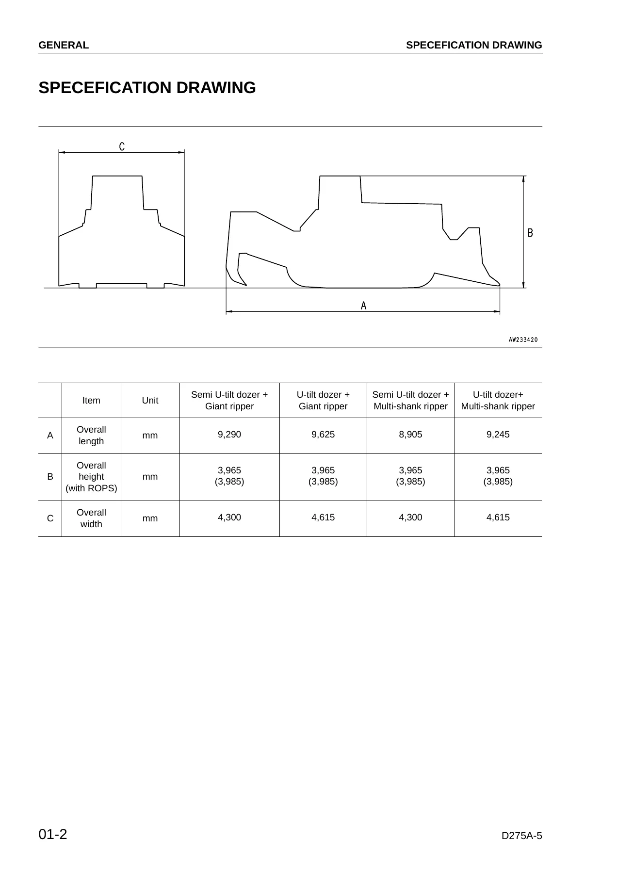
01 – General
Specification drawings, machine specifications, a component weight table and the complete fuel, coolant and lubricant chart. This chapter also includes the foreword, safety notices, standard tightening torque tables (metric bolts, split flange bolts, O-ring boss piping joints, O-ring boss plugs, Cummins engine bolts/nuts, eye joints and tapered screws), hose tightening torques (taper seal and face seal types), the electric wire colour/thickness code system, and the full millimetre-to-inch, kilogram-to-pound, litre-to-gallon, kgm-to-ft·lb, kg/cm²-to-lb/in² and Fahrenheit-to-Centigrade conversion tables. It is where every general reference value used elsewhere in the manual is established.
10 – Structure, Function and Maintenance Standard
The largest technical chapter, covering the entire machine system by system with cutaway illustrations, exploded views and maintenance-standard tables. Coverage includes:
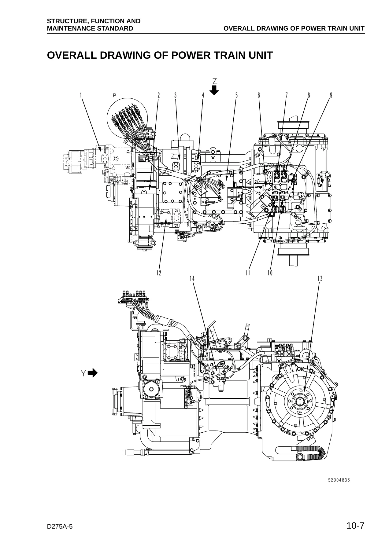
- Power train – overall power train unit layout, damper and universal joint, torque converter, PTO, scavenging pump, transmission control, transmission (planetary gear and clutch operation for all forward and reverse speeds), transmission ECMV, main relief valve, torque converter valve, power train pump, steering lubrication pump, lubrication relief valve.
- Steering and brake – steering/brake control, bevel gear shaft, steering clutch and brake assembly, steering control valve, steering clutch ECMV, steering brake ECMV, parking brake valve, sudden brake prevention valve.
- Final drive and undercarriage – final drive, sprocket (including a full-scale sprocket tooth profile), track frame, recoil spring, idler, track roller, carrier roller, track roller bogie, track shoe, main frame and suspension.
- Work equipment hydraulic system – hydraulic piping diagram, PPC control piping diagram, work equipment control, work equipment pump (HPV95), cooling fan pump (LPV45), cooling fan motor (LMF75), hydraulic tank, accumulator, PPC lock valve, PPC valves for blade lift/tilt and ripper, hydraulic cylinders, piston valve, quick drop valve and pin puller switch.
- Control valve, blade, ripper, cab and electronics – control valve operation (including LS valve, pressure compensation, meter-out control, relief, compound operation, unload valve preset and dual tilt/pitch systems), self-reducing pressure valve, cylinder stay, blade, ripper equipment, cab mount, cab, ROPS guard, air conditioner, engine control, deceleration potentiometer, CRI engine control system, monitor system, monitor panel, sensors, mode selection system (SSC specification), electrical equipment and the Palm Command Control System.
Every one of these sections includes a maintenance-standard table with standard size, tolerance, standard clearance, repair limit and remedy columns.
20 – Testing and Adjusting
The standard-value tables for engine and chassis, followed by the complete testing and adjusting procedures and the full troubleshooting section. Engine tests cover speed (high/low idle, rated), intake air (boost) pressure, exhaust temperature, exhaust gas colour, valve clearance, compression pressure, blow-by pressure and engine oil pressure. Chassis tests cover power train oil pressures (torque converter inlet/outlet, transmission main relief, F/R/1st/2nd/3rd clutch, steering clutch/brake, lubrication, sudden-stop prevention valve output), brake performance, PCCS lever and pedal stroke/effort, track shoe tension, work equipment oil pressure (unload, main relief, LS), control circuit main pressure, PPC valve output pressure, fan motor speed and fan circuit pressure. The chapter also contains the full EMMS monitor panel special-function procedures, adjustment mode tables and the E-mode / H-mode / S-mode troubleshooting guides with connector pin-out tables and full circuit drawings for the monitor, engine, transmission and steering controller systems.
30 – Disassembly and Assembly
Complete removal, installation, disassembly and assembly procedures for every major component and sub-assembly: fuel supply pump, fuel injector, nozzle tip, engine front and rear seals, cylinder head, fuel tank, main radiator, sub-radiator, hydraulic oil cooler, radiator guard, engine, damper, power train unit, PTO, torque converter, TORQFLOW transmission, steering case, scavenging pump, work equipment pump, fan pump, power train and steering lubricating oil pump, final drive, track frame, idler, recoil spring, track roller, carrier roller, bogies, track shoe (including whole disassembly/assembly, field link disassembly/assembly and master link procedures), pivot shaft, equalizer bar, work equipment control valve, hydraulic cylinders, blade, ripper, ROPS guard, operator’s cab, floor frame, controllers, engine hood, fan drive and fan motor. Each section identifies the special tools required and gives the specified tightening torques, press-fitting forces and clearances.
90 – Others
Full power train hydraulic circuit diagram, work equipment hydraulic circuit diagram for both single-tilt and dual-tilt specifications, the complete electrical circuit diagram split across four sheets, the air conditioner electrical circuit diagram and the electric circuit diagram for inside the cab. These are the master reference drawings that tie every electrical and hydraulic component in the machine together.
What This Komatsu D275A-5 Shop Manual Lets You Do
With this manual on hand, you can diagnose and repair every major system on the D275A-5 crawler dozer – the SDA6D140E-3 engine, torque converter and TORQFLOW transmission, steering clutches and brakes, final drives, undercarriage, blade and ripper hydraulics, and the electronic control systems that manage them. You get the exact tightening torques, wear limits, clearance standards, test pressures and adjustment procedures the factory specifies, so bearings, seals, clutch packs and hydraulic components go back together correctly and stay together. The troubleshooting guides let you trace a fault through the ECMV circuits, PPC pressures, sensor inputs and controller logic before you start pulling parts.
IMAGES PREVIEW
Because it is a searchable PDF, you can jump straight to the section you need, print the pages for the job at hand, and keep the full manual on a laptop, tablet or phone in the workshop or in the field. There is no shipping, no waiting and no physical book to damage – the download link is available immediately after payment.
Reviews
There are no reviews yet.