
Komatsu D41E-6 & D41P-6 Crawler Dozer Shop Manual SEBM007009 – PDF Repair & Service Guide
Original price was: $63.95.$39.95Current price is: $39.95.
Complete Komatsu D41E-6 and D41P-6 shop manual SEBM007009 in PDF. Structure and function, testing and adjusting, disassembly and assembly, and maintenance standards for the S6D102-1 crawler dozer.
Description
Komatsu D41E-6 and D41P-6 Shop Manual — SEBM007009
This PDF shop manual covers the Komatsu D41E-6 and D41P-6 crawler dozers, including the power angle tiltdozer configuration. It is the complete chassis-side workshop reference — structure and function, testing and adjusting, disassembly and assembly, and maintenance standards — issued under document number SEBM007009. The D41E-6 and D41P-6 mount the S6D102-1 engine, and this manual works alongside the 102 Series Engine Shop Manual for engine-specific overhauls.
File Details
- Manual type: Shop Manual (chassis volume)
- Brand: Komatsu
- Models covered: D41E-6, D41P-6
- Engine: S6D102-1 (S6D102E-1 on later serial ranges)
- Document number: SEBM007009
- Language: English
- Format: PDF — instant download, printable, viewable on any device
Chapters Covered
- 01 General
- 10 Structure and Function
- 20 Testing and Adjusting
- 30 Disassembly and Assembly
- 40 Maintenance Standard
- 90 Others
01 General
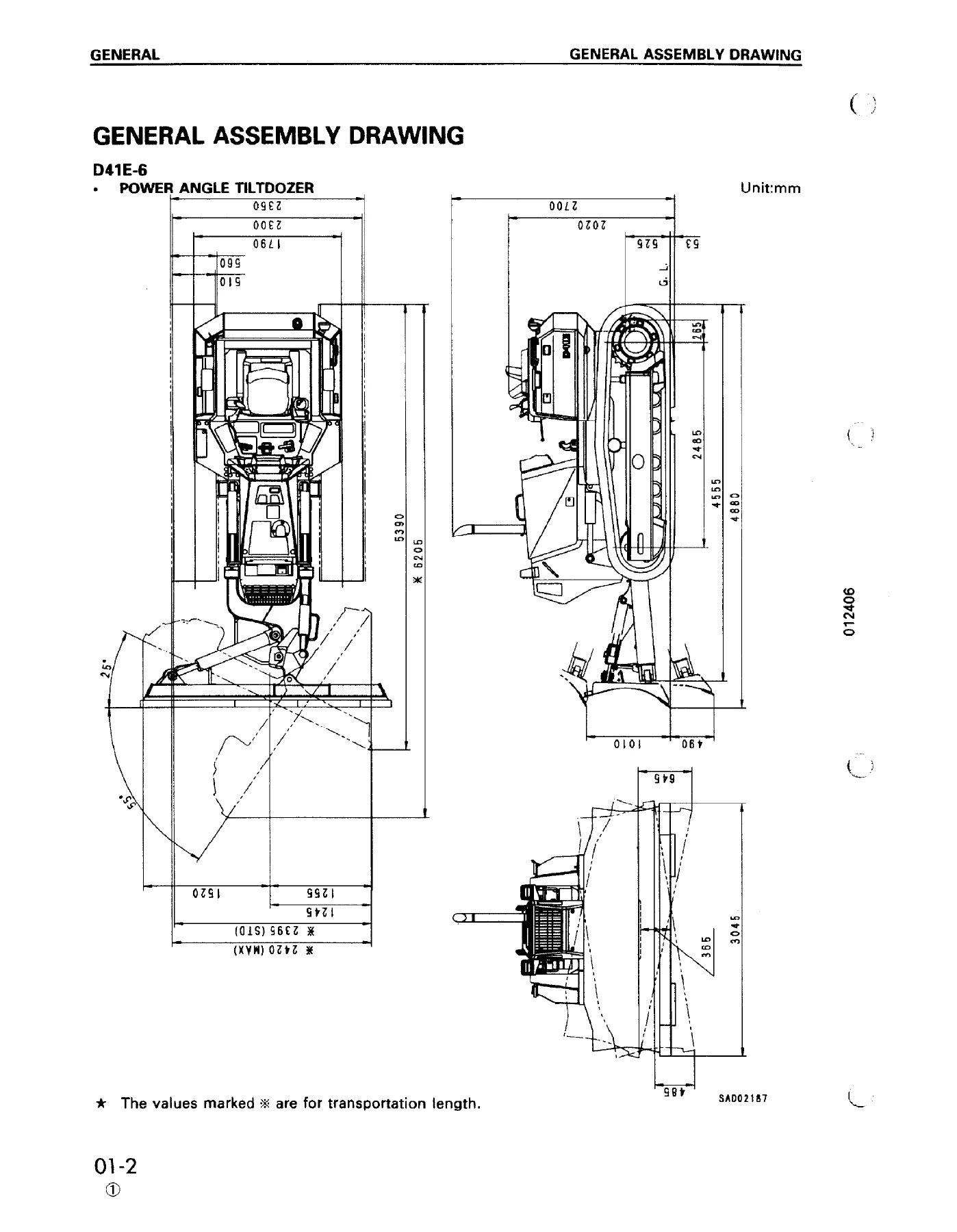
Opens with the general assembly drawing of the power angle tiltdozer, followed by the full machine specifications for both the D41E-6 and D41P-6 — operating weights for bare tractor, power angle tiltdozer, and the power angle tilt plus winch and ROPS cab build; gradeability and stability figures; forward and reverse speeds through all three ranges; ground pressure; dimensions and overall heights; and the undercarriage, hydraulic, and work equipment data. A weight table lists lift weights for major components — engine and damper assembly, radiator, fuel tank, transmission, steering clutch and brake, final drive, frame, and the complete power angle tiltdozer assembly. The chapter closes with the table of fuel, coolant, and lubricants and the specified and refill capacities.
10 Structure and Function
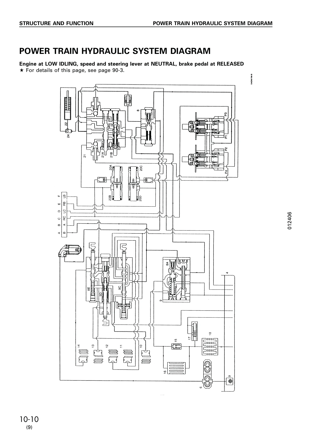
Explains how each major system on the D41E-6 and D41P-6 works. Coverage includes the radiator and oil cooler layout, engine control linkage, the complete power train system with its hydraulic piping and circuit diagrams, damper and universal joint, transmission control and the transmission control valve, steering, brake and inching control, bevel gear shaft, steering clutch and steering brake, the steering PPC valve, steering piston, priority valve, brake valve, power train oil filter, and final drive. The frame assembly, track frame, and recoil spring are described next, followed by work equipment hydraulic piping, control, and circuit diagrams, hydraulic tank and filter, main control valve, and the CLSS pressure-compensated load-sensing system. Later sections cover the air conditioner, electrical wiring and circuit diagrams, engine control system, machine monitor system, and the sensors used across the machine.
20 Testing and Adjusting
This is the troubleshooting and calibration chapter. It starts with the standard value tables for engine-related parts, chassis-related parts, and the machine monitor, then walks through individual procedures — adjusting valve clearance, measuring blow-by, fuel injection timing, exhaust colour, engine oil pressure, and engine speed, adjusting the fuel control linkage and decelerator pedal linkage, engine stop solenoid setup, steering, directional and gear shift lever adjustment, main brake and parking brake testing, brake and clutch lining wear inspection, lever assembly and lining clearance adjustment, brake pedal, inching pedal and parking brake linkage adjustment, work equipment control and safety lever linkage, power train oil pressure measurement, work equipment circuit pressure, track shoe tension, internal cylinder leakage, air bleeding, and releasing the parking brake. A long troubleshooting section follows, split into engine system (S mode), electrical system (E mode), hydraulic and mechanical system (H mode), and machine monitor system (M mode), each with its own diagnostic charts.
30 Disassembly and Assembly
The teardown and rebuild chapter. It covers removal and installation of the starting motor, alternator, engine oil cooler core, fuel injection pump, water pump, turbocharger, nozzle holder, thermostat, engine hood, cylinder head, fuel tank, radiator and oil cooler, hydraulic cooler, engine, radiator guard, and damper. Transmission removal, installation, disassembly, and assembly are covered in full, along with the PTO, steering case, priority valve, brake control valve, transmission shift valve, transmission pressure valve, steering piston, parking brake cylinder, final drive, idler and recoil spring, track roller, carrier roller, and track shoe — including overall track disassembly and assembly with link press jig dimensions and field one-link procedures. Hydraulic pump, main control valve, main relief valve, steering PPC valve, blade angle, lift and tilt cylinders, hydraulic tank, ROPS roof and guard, canopy, operator’s cab, cab glass, floor frame, air conditioner compressor and condenser, and monitor removal and installation round out the chapter. Required special tools are listed with part numbers and sketches, and torque values are given throughout.
40 Maintenance Standard
Gives the wear limits, standard sizes, tolerances, and repair limits used to judge disassembled parts. Individual sections cover the damper and universal joint, hydraulic and power train pump, transmission, transmission control valve, bevel gear shaft, steering clutch and steering brake, steering PPC valve, steering piston, priority valve, brake valve, parking brake cylinder, final drive, track frame and recoil spring, idler, track roller, carrier roller, track shoe, main control valve, work equipment cylinders, and work equipment.
90 Others
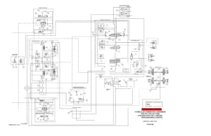
Collects the full-size reference diagrams: power train hydraulic system diagram, power train hydraulic circuit diagram, work equipment hydraulic system and circuit diagrams, actual electric wiring diagram, and the electrical circuit diagrams for cab and non-cab machines across the covered serial ranges.
What This Komatsu D41E-6 and D41P-6 Shop Manual Lets You Do
With this manual on hand you can carry out a full range of jobs on the D41E-6 and D41P-6 crawler dozer — from routine valve clearance and linkage adjustments to a complete transmission rebuild or final drive overhaul. The power train, steering, brake, and work equipment systems are covered in enough detail that you can diagnose a fault, measure the correct pressures, and repair the assembly to the figures the machine was built to. The standard value tables and maintenance standards give you the wear limits and clearances needed to decide whether a part can be reused or must be replaced, and the torque values remove the guesswork from reassembly.
The troubleshooting charts let you work from a symptom to a cause without tearing the machine apart first — engine system, electrical system, hydraulic and mechanical system, and machine monitor system each have their own diagnostic path. For a machine in commercial service, that means less downtime and fewer parts ordered on a hunch.
Delivered as a PDF straight after checkout. No shipping, no waiting, no binder to lose. Open it on a laptop in the workshop, a tablet in the cab, or a phone at the jobsite, and print the pages you need for the job in front of you. Instant access, yours to keep.
IMAGES PREVIEW

Reviews
There are no reviews yet.