
Komatsu D61EX-15 & D61PX-15 Bulldozer Shop Manual – Complete Service & Repair Guide
Original price was: $44.95.$26.95Current price is: $26.95.
988-page Komatsu D61EX-15 and D61PX-15 Bulldozer Shop Manual (WE051Z0002) covering the SA6D114E-2 engine, power train, HSS, undercarriage, hydraulics, work equipment, and electrical system with full testing, troubleshooting, and disassembly procedures.
Description
Komatsu D61EX-15 & D61PX-15 Bulldozer Shop Manual — Complete Service & Repair Guide
This is the complete Komatsu D61EX-15 and D61PX-15 Bulldozer Shop Manual, document number WE051Z0002, covering machines from serial number B40001 and up. At 988 pages, it is the full service reference for these crawler dozers, spanning the SA6D114E-2 diesel engine and cooling system, power train, hydrostatic steering system (HSS), undercarriage, hydraulic system, work equipment, cab, and electrical system. Every major assembly is documented with structure and function explanations, maintenance standards, testing and adjusting procedures, troubleshooting guidance, and step-by-step disassembly and assembly instructions.
File Details
- Manual type: Shop Manual (Service, Repair, Troubleshooting, Disassembly & Assembly)
- Brand: Komatsu
- Models covered: D61EX-15, D61PX-15
- Serial numbers: B40001 and up
- Engine: Komatsu SA6D114E-2 diesel engine
- Document number: WE051Z0002
- Language: English
- Page count: 988
- File format: PDF
- Publication date: 09-04 (2004)
Chapters Covered
The manual is organized into the following sections, each built around the components and systems that make up the D61EX-15 and D61PX-15:
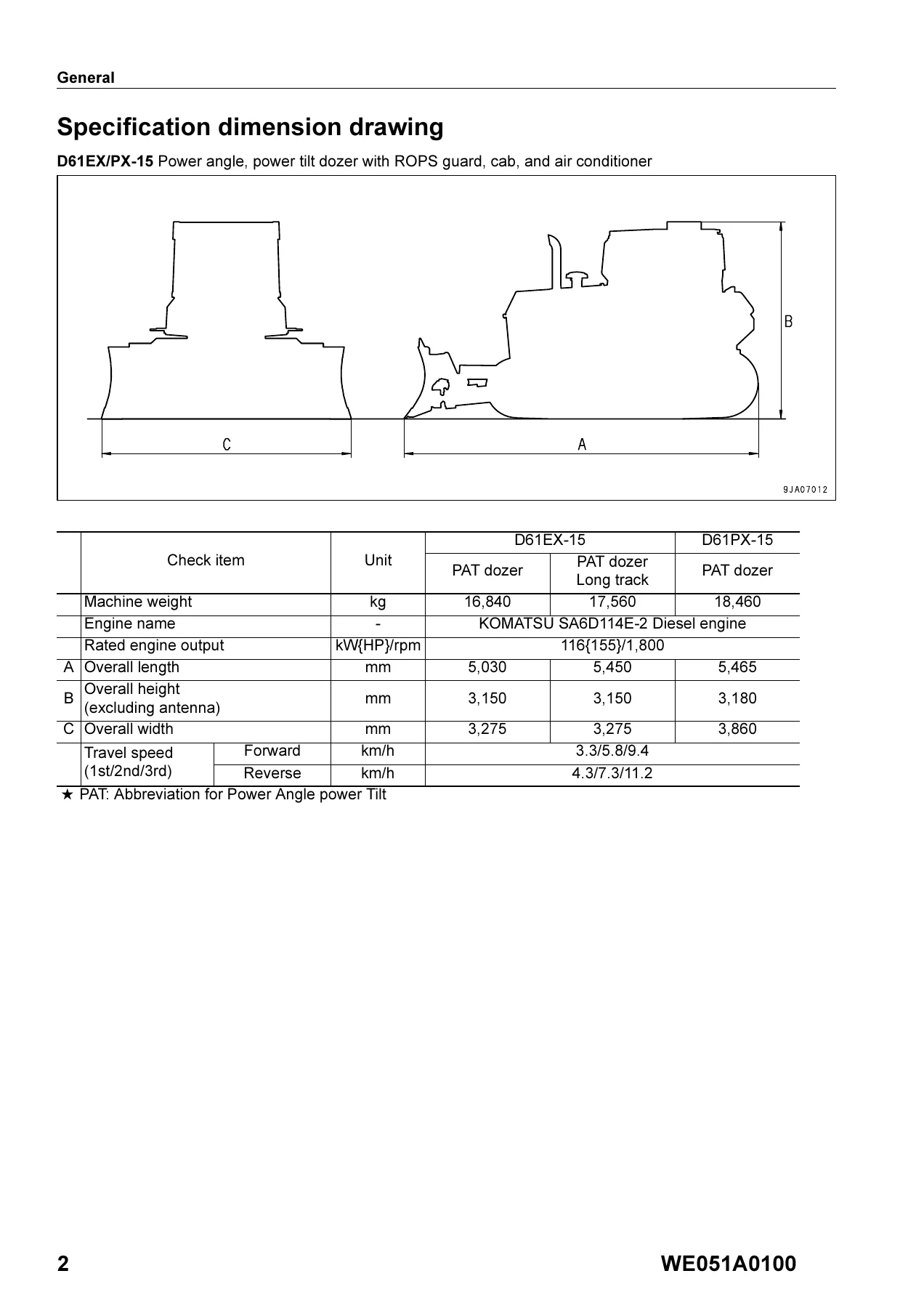
- General — Specification dimension drawings, full specifications, weight table, oil and coolant table for both the D61EX-15 and D61PX-15 configurations (standard, long track, PAT dozer).
- Structure and Function / Maintenance Standard
- Engine and cooling related components — Cooling system, cooling fan motor, radiator, power train oil cooler, hydraulic oil cooler
- Power transmitting system — Power train outline, power train skeleton, overall drawing of power train unit, hydraulic piping diagram, damper and universal joint, transmission/steering/brake control
- Torque converter and PTO — Structure, function, PTO drive gears, pump mounting
- Transmission — Planetary gear mechanisms, disc clutches, gear speeds and operated clutches, forward/reverse/1st/2nd/3rd clutch operation
- Transmission ECMV — Pressure control valve, fill switch, proportional solenoid, ECMV operation
- Main relief valve and lubricating oil relief valve — Torque converter relief operation, main relief operation
- Scavenging pump and power train/lubrication pump — Specifications, structure, side clearance, capacity
- HSS system — HSS pump (HPV95), HSS motor (HM80), HSS assembly, counterbalance valve, check valve, safety valve
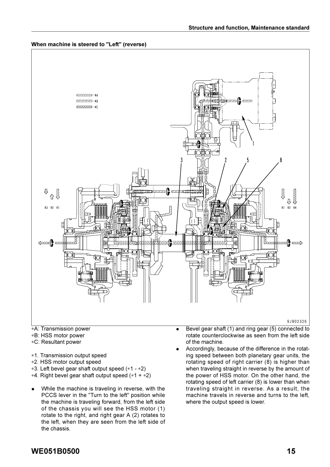
- Bevel gear shaft, HSS and brake — Bevel gear shaft, transfer section, planetary gear section, brake operation
- Brake valve — Main brake valve, parking brake valve, brake modulation
- Final drive — Spur gear double reduction type, backlash, bearing preload, sprocket assembly
- Undercarriage — Frame assembly, suspension, track frame and recoil spring, idler, track roller, carrier roller, sprocket, track shoe, track tension
- Hydraulic system — Cooling fan pump, cooling fan motor, PPC valve, electric lever (steering), control valve, CLSS (Closed center Load Sensing System), self-pressure reducing valve
- Work equipment — Power angle power tilt dozer, power tilt dozer, semi-U dozer, cutting edge and end bit, ripper
- Cab and its attachments — Cab mount, cab, ROPS guard, air conditioner piping
- Electric system — Engine control system, cooling system control system, Palm command control system (PCCS), PPC lock system, monitor system, monitor panel (EMMS), sensors
- Standard Value Tables — Engine standard values (idle speeds, boost pressure, compression, oil pressure, belt tension) and chassis standard values (lever strokes, operating efforts, power train pressures, HSS pressures, travel speeds, work equipment pressures and speeds).
- Testing and Adjusting — Tools for testing and troubleshooting, engine speed measurement, intake air pressure (boost pressure), exhaust color, valve clearance adjustment, compression pressure, blow-by pressure, fuel injection timing, engine oil pressure, air conditioner belt tension, engine speed sensor adjustment, fuel control linkage adjustment, power train oil pressure measurement, transmission speed sensor replacement, brake performance testing, brake pedal and parking brake adjustment, idler clearance, sprocket wear inspection, track shoe tension, work equipment and HSS oil pressure testing, control circuit main pressure, PPC valve output pressure, work equipment PPC valve play, cylinder internal leakage, safety lock lever, residual pressure release, air bleeding, fan pump circuit pressure, fan motor speed, HSS motor oil leakage, cab testing.
- Troubleshooting — Error code display and troubleshooting (transmission clutch, forward/reverse/1st/2nd/3rd clutch fill signals, engine overrun, alternator, oil pressure, coolant, power train oil, hydraulic oil, battery relay, safety relay, backup alarm relay, preheater relay, CAN communication, steering and transmission controller, shift switches, travel lock switch, engine oil pressure switch, pitch control switch, sensors, solenoids, ECMV, governor motor, engine stop solenoid). E-mode (electrical system), H-mode (hydraulic and mechanical system), and S-mode (engine system) troubleshooting charts. Connector arrangement drawings and electrical circuit diagrams.
- Disassembly and Assembly — Engine related procedures (fuel injection pump, cylinder head, engine front and rear seals, engine assembly, damper, radiator guard, radiator and hydraulic oil cooler, fan drive, fan motor, engine hood, fuel tank), power train (PTO, torque converter, transmission, torque converter main relief valve), power train continued (power train and lubricating oil pump, HSS and work equipment pump, scavenging pump, HSS motor, HSS assembly, final drive), undercarriage (track frame, idler, recoil spring, track roller, carrier roller, track shoe, pivot shaft, equalizer bar, segment teeth), hydraulic system (main control valve, cooling fan pump, work equipment, hydraulic cylinder), others (operator’s cab, cab glass, ROPS canopy, dashboard, floor frame, steering and transmission controller).
For a technician or owner working on a D61EX-15 or D61PX-15, this manual gives you the same reference material a Komatsu service workshop would use. The Structure and Function chapters explain how each system works before you touch it, the Maintenance Standard sections provide the wear limits and clearances needed to judge whether a component is reusable, the Testing and Adjusting procedures walk through pressure measurements and linkage adjustments, the Troubleshooting sections help isolate faults by symptom or error code, and the Disassembly and Assembly instructions cover removal, installation, and overhaul with torque values, special tools, and assembly precautions throughout.
What This Shop Manual Enables You to Do
The D61EX-15 and D61PX-15 are complex machines with electronically controlled transmissions, hydrostatic steering, and multiple hydraulic circuits. This manual supports the full range of service work:
- Engine service — Adjust valve clearance on the SA6D114E-2, test compression and blow-by, set fuel injection timing, measure boost pressure, and diagnose starting, output, and exhaust problems through the S-mode troubleshooting charts.
- Power train repair — Measure transmission main relief pressure and individual clutch pressures (forward, reverse, 1st, 2nd, 3rd), diagnose ECMV faults through error codes, disassemble and assemble the TORQFLOW transmission with piston stroke checks and tie bolt torques, and service the torque converter and PTO.
- HSS and steering — Understand the hydrostatic steering system, test HSS pump and motor pressures, measure HSS motor leakage, adjust the HSS LS relief valve, and disassemble/assemble the HSS unit including bevel gear shaft, planetary gears, and brake.
- Hydraulic system — Test unload pressure, main relief pressure, PPC valve output pressure, and work equipment relief pressures; measure internal leakage in blade lift, tilt, and angle cylinders; adjust blade and ripper PPC valve play; bleed air from circuits; and diagnose control valve, CLSS, and self-pressure reducing valve issues.
- Undercarriage — Adjust track shoe tension, inspect sprocket wear, measure and adjust idler clearance, disassemble and assemble track rollers, carrier rollers, idler, and recoil spring, and service the track shoe assembly including link press-fitting and field replacement of a single link.
- Electrical diagnostics — Use the E-mode troubleshooting charts and connector arrangement drawings to trace faults in the engine control, cooling fan control, PCCS, PPC lock, and monitor systems. The error code table lists each code, the defective part, the trouble condition, and the action code displayed on the monitor panel.
- Work equipment — Disassemble and assemble the blade, angle cylinder, tilt cylinder, lift cylinder, and ripper; measure hydraulic drift; and replace cutting edges and end bits.
- Cab and operator station — Remove and install the cab, replace stuck glass, service the ROPS canopy, dashboard, floor frame, and steering/transmission controller.
Why This Manual Matters
Working on a bulldozer without the correct specifications is a gamble. Transmission clutch pressures outside the specified range, an incorrectly adjusted HSS relief valve, or a track tension that is too loose or too tight can all lead to premature wear or catastrophic failure. The maintenance standards in this manual give you the exact clearances and wear limits for every major component — from the transmission clutch disc thickness and spring free lengths to the final drive backlash and bevel gear preload — so you can measure a part and know whether it is within service limits or needs replacement.
The troubleshooting sections are structured to save time. Rather than guessing at a fault, you start from the symptom or the error code and work through the possible causes in order of probability. The error code table maps each code to the defective part and the action taken by the controller, and the E-mode, H-mode, and S-mode charts give you the specific measurement or inspection that confirms or eliminates each cause.
IMAGES PREVIEW
Instant PDF Delivery
The manual is delivered as a PDF file that you can download immediately after purchase. There is no shipping and no waiting. You can view it on any device — laptop, tablet, or smartphone — and print the pages you need for the workshop. The full 988-page document is yours to keep and reference whenever you service or repair your D61EX-15 or D61PX-15.
Reviews
There are no reviews yet.