
Komatsu PC200-8 PC200LC-8 PC220-8 PC220LC-8 Hydraulic Excavator Shop Manual – Full PDF Service & Repair Guide SEN00084-07
Original price was: $67.95.$44.95Current price is: $44.95.
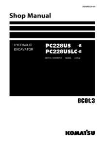
Complete Komatsu Shop Manual for PC200-8, PC200LC-8, PC220-8 and PC220LC-8 hydraulic excavators (Form SEN00084-07). 1,082 pages of specifications, standard values, testing and adjusting procedures, failure-code troubleshooting, disassembly/assembly steps, torque tables and hydraulic/electrical diagrams. Instant PDF download.
Description
Komatsu PC200-8, PC200LC-8, PC220-8 and PC220LC-8 Hydraulic Excavator Shop Manual – SEN00084-07
This is the full Komatsu shop manual for the PC200-8, PC200LC-8, PC220-8 and PC220LC-8 hydraulic excavators, published under form number SEN00084-07 and applying to machines from PC200-8 300001 and up, PC200LC-8 300001 and up, PC220-8 70001 and up and PC220LC-8 70001 and up. It is the same multi-part document Komatsu issues for workshop use: engine and hydraulic specifications, standard values, testing and adjusting procedures, failure-code troubleshooting, disassembly and assembly of the major components, and the hydraulic and electrical diagrams needed behind the job. Everything is contained in a single PDF – no loose sections, no missing Form numbers.
File Details
- Manual type: Shop Manual (service, repair, testing and troubleshooting)
- Brand: Komatsu
- Models covered: PC200-8, PC200LC-8, PC220-8, PC220LC-8
- Engine: SAA6D107E-1
- Form number: SEN00084-07
- Language: English
- File format: PDF
- Page count: 1,082 pages
Chapters Covered
- 00 Index and Foreword
- 01 Specification
- 10 Structure, Function and Maintenance Standard
- 20 Standard Value Table
- 30 Testing and Adjusting
- 40 Troubleshooting
- 50 Disassembly and Assembly
- 90 Diagrams and Drawings
00 Index and Foreword
Safety notice, how to read the shop manual, explanation of terms used for maintenance standard, handling of electric equipment and hydraulic components, handling of connectors newly used for engines, how to read the electric wire code, precautions for operation, disassembly and connection of push-pull type couplers, the standard tightening torque table and the conversion tables. This is the chapter that sets the working rules for everything that follows.
01 Specification
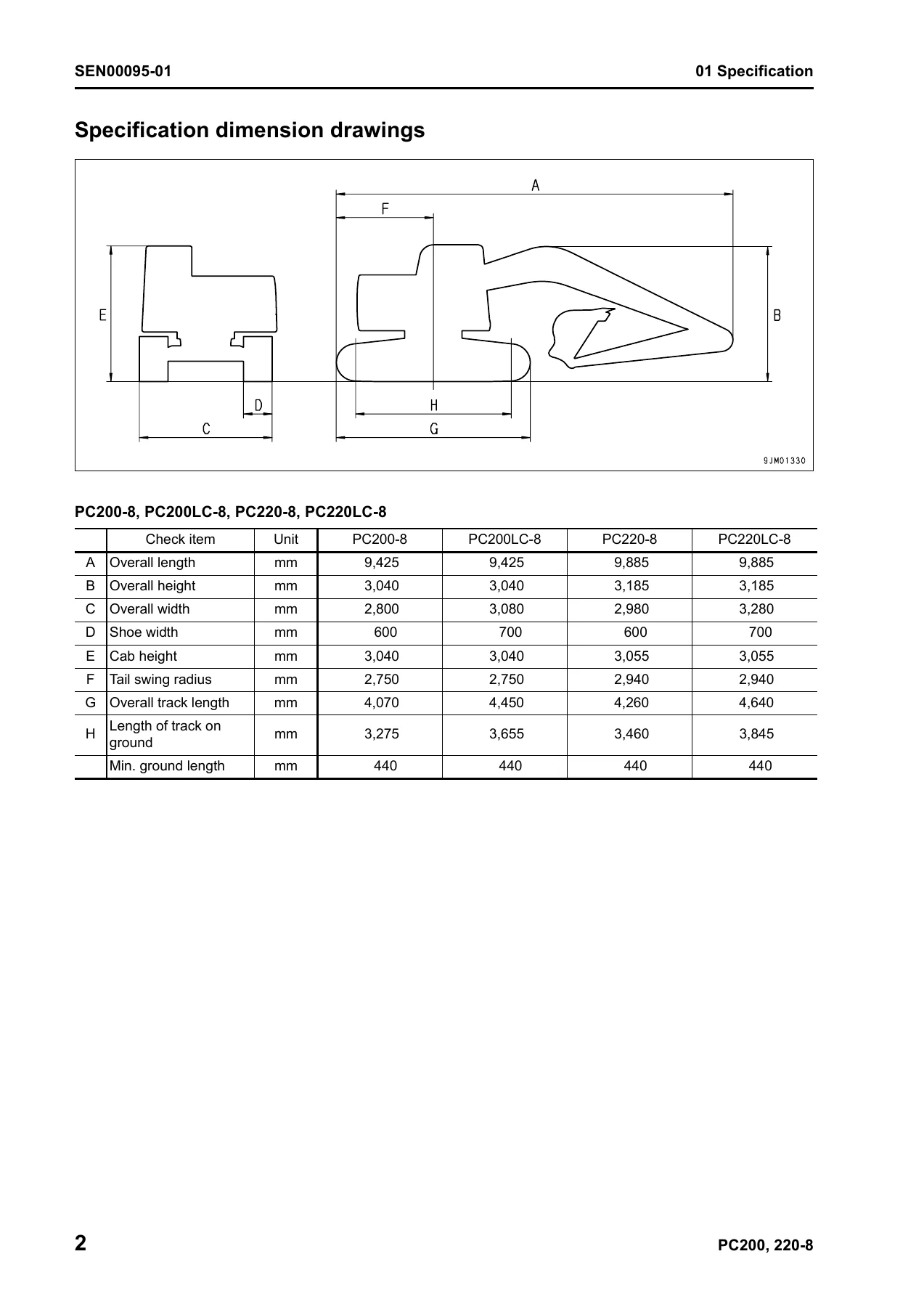
Specification dimension drawings, working range diagram, full machine specifications and weight tables for the PC200-8, PC200LC-8, PC220-8 and PC220LC-8, plus the table of fuel, coolant and lubricants. It is the reference chapter for confirming bucket capacity, operating weight, digging depth, digging reach, ground pressure, travel speeds, engine output, hydraulic pump delivery and cylinder dimensions before any job begins.
10 Structure, Function and Maintenance Standard
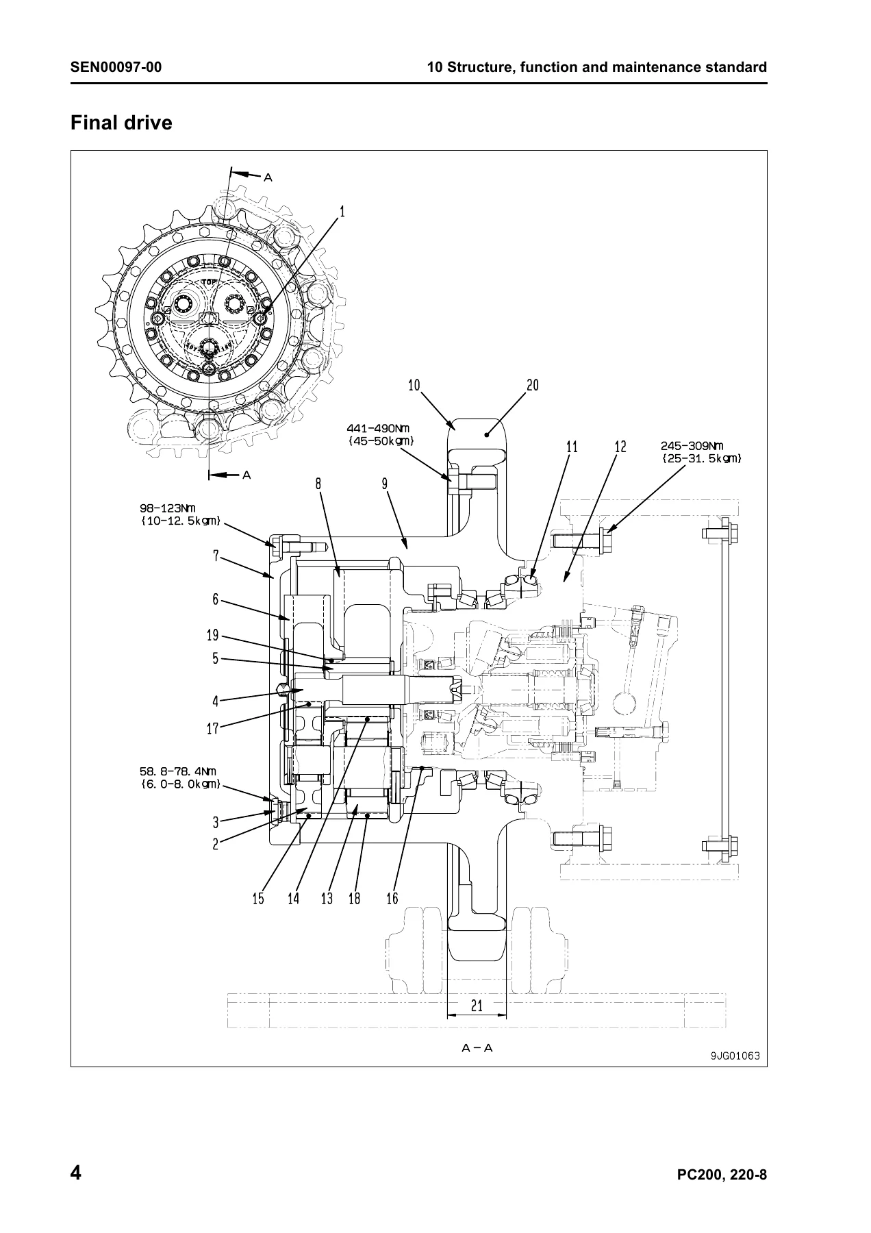
The largest section of the manual. It runs through engine and cooling system, power train (final drive, swing machinery, swing circle), undercarriage and frame (track frame, recoil spring, idler, carrier roller, track roller, track shoe), the hydraulic system in three parts (equipment layout, hydraulic tank and filter, hydraulic pump, control valve, CLSS, functions and operation by valve, swing motor, center swivel joint, travel motor, PPC valves, solenoid valves, hydraulic cylinders), work equipment, cab and attachments, and the electrical system (engine control, electrical control system, monitor system, sensors and KOMTRAX terminal). Each sub-section explains the structure, then the function, then the maintenance standard values and remedies needed for service.
20 Standard Value Table
A dedicated table chapter that separates engine-related and chassis-related standard values for new machines from judgement criteria for testing, adjusting and troubleshooting. It is used to decide whether a reading is within tolerance or a part needs attention.
30 Testing and Adjusting
Three parts of test procedures with the tools required. Part 1 covers engine speed, intake air pressure (boost pressure), exhaust gas colour, valve clearance, compression pressure, blow-by pressure, engine oil pressure, fuel system handling, fuel pressure, fuel return rate and leakage, air bleeding, fuel circuit leak checks, air conditioner belt tension, fan belt replacement, swing circle bearing clearance, track shoe tension, work equipment/swing/travel oil pressures, control circuit basic pressure, pump PC and LS control circuit pressures, solenoid valve output pressures, PPC valve output pressures, PPC valve play, hydraulic drift diagnosis, residual pressure release, oil leakage measurement, air bleeding of each part, cab tipping stopper and mirror adjustment. Part 2 covers the special functions of the machine monitor. Part 3 covers the engine controller voltage circuit, preparation for electrical troubleshooting, diode testing and Pm Clinic service.
40 Troubleshooting
Structured for real diagnostic work. It opens with the failure codes table and fuse locations, general information on troubleshooting, points to remember, sequence of events and check-before-troubleshooting items. Troubleshooting by failure code is split across four parts, covering engine controller, sensors, injectors, common rail, electrical and hydraulic components. E-mode covers the electrical system; H-mode covers the hydraulic and mechanical system; S-mode covers the engine. Each entry gives the possible causes, standard values and the specific check that isolates the failure.
50 Disassembly and Assembly
Component-level removal, installation, disassembly and assembly procedures with special tool references, tightening torques and coating materials. It covers the fuel supply pump, fuel injector, engine front and rear seals, cylinder head, radiator, hydraulic oil cooler, aftercooler, fuel cooler, and engine and hydraulic pump assembly; final drive, swing motor and swing machinery, swing circle; carrier roller, track roller, idler, recoil spring, sprocket, track shoe, revolving frame and counterweight; center swivel joint, hydraulic tank, control valve, hydraulic pump, input shaft oil seal, PPC valve assemblies and hydraulic cylinders; work equipment; operator’s cab, cab glass and front window; and the air conditioner, KOMTRAX, monitor, pump controller and engine controller.
90 Diagrams and Drawings
Hydraulic circuit diagrams and electrical circuit diagrams, arranged so the technician can trace a circuit or a hydraulic line without leaving the workshop bench.
What This Komatsu Shop Manual Lets You Do
Every procedure in this PDF is written for the person actually holding the wrench. You can set valve clearance on the SAA6D107E-1, measure compression and blow-by, verify engine oil pressure at high and low idle, bleed the fuel circuit after a filter change, check fuel return rate from the supply pump, pressure limiter and injector, and confirm low-pressure and return circuit pressures against the standard value table. You can test the main relief valves, swing relief valve and travel relief valve, read the pump PC and LS control circuit pressures, adjust the LS differential pressure, measure PPC output pressures, verify the PC-EPC and LS-EPC valve outputs, and prove whether hydraulic drift is coming from the cylinder packing or from the control valve. You can interpret failure codes displayed on the machine monitor, work through the E-mode, H-mode and S-mode troubleshooting trees, and know exactly which connector, pin or sensor to check next.
When a component has to come out, the disassembly and assembly chapter tells you the correct order, the special tools to use, the tightening torques for every bolt and the coating materials for every joint. Final drive, swing machinery, hydraulic pump, control valve, hydraulic cylinders, track frame and revolving frame – the procedures are laid out step by step, with the measurement checks that confirm the job was done right.
Why the Right Manual Matters on a Komatsu Excavator
The PC200-8, PC200LC-8, PC220-8 and PC220LC-8 share a common architecture but differ in engine output, pump set pressure, operating weight, track roller count, hydraulic cylinder diameters and travel motor variant. Guessing torque values, relief pressures or standard clearances on these machines is how components get damaged, hydraulic pumps get destroyed and downtime stretches into weeks. This shop manual removes the guesswork. The standard value table gives you the tolerance, the testing and adjusting chapter gives you the test, and the troubleshooting chapter tells you what the reading means. From a routine valve clearance check to a full swing machinery rebuild, the numbers and the sequence are in one place.
IMAGES PREVIEW
Instant PDF Delivery
The manual is delivered as a single downloadable PDF immediately after purchase. There is no shipping, no waiting on a courier and no separate binder to buy. Open it on a laptop on the tailgate of the service truck, on a tablet on the bench, or print just the pages you need for the job at hand. Keep it on the workshop computer, keep a copy on your phone, and the whole 1,082-page shop manual goes wherever the machine does.
Reviews
There are no reviews yet.