
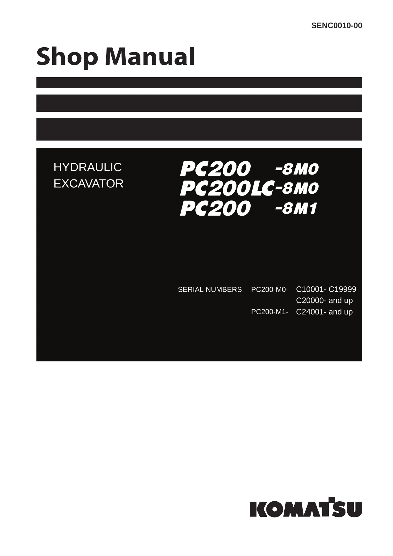
Komatsu PC200-8M0, PC200LC-8M0, PC220-8M0, PC220LC-8M0 & PC200-8M1 Hydraulic Excavator Shop Manual SENC0010-00 – PDF Download
Original price was: $63.95.$39.95Current price is: $39.95.
Complete Komatsu shop manual SENC0010-00 for PC200-8M0, PC200LC-8M0, PC220-8M0, PC220LC-8M0 and PC200-8M1 hydraulic excavators. 1,566 pages covering the SAA6D107E-1 engine, CLSS hydraulics, undercarriage, electrical system, troubleshooting, disassembly and hydraulic/electrical diagrams.
Description
Komatsu PC200-8M0, PC200LC-8M0, PC220-8M0, PC220LC-8M0 and PC200-8M1 Hydraulic Excavator Shop Manual SENC0010-00
This is the complete Komatsu shop manual for the PC200-8M0, PC200LC-8M0, PC220-8M0, PC220LC-8M0 and PC200-8M1 hydraulic excavators, published under document number SENC0010-00. Every major system is covered at working workshop depth: the SAA6D107E-1 engine and cooling system, the power train including final drive, swing machinery and swing circle, the undercarriage and frame, the full CLSS hydraulic system spanning pump, control valve, swing motor, travel motor, PPC valves and cylinders, the work equipment, and the electrical system from engine control and the machine monitor through to sensors, KOMTRAX and the air conditioner.
Serial number coverage runs across all five variants: PC200-8M0 and PC200LC-8M0 from C10001-C19999 and C20000 and up, PC220-8M0 and PC220LC-8M0 from 100001 and up, and PC200-8M1 from C24001 and up. The engine in every case is the SAA6D107E-1.
File Details
- Manual type: Shop Manual (Service and Repair)
- Brand: Komatsu
- Document number: SENC0010-00
- Language: English
- Page count: 1,566 pages
- File format: PDF
- Publication date: 06-20 (June 2020)
Chapters Covered
- 00 Index and foreword
- 01 Specification
- 10 Structure, function and maintenance standard
- 20 Standard value table
- 30 Testing and adjusting
- 40 Troubleshooting
- 50 Disassembly and assembly
- 80 Appendix — Air conditioner
- 90 Diagrams and drawings
Index and Foreword
Safety notices, general precautions, slinging and signal procedures, the standard tightening torque tables for bolts, nuts and hydraulic joints, conversion tables, and the full abbreviation list. Read this section first if you are not already familiar with Komatsu’s workshop conventions — the torque tables in particular are the ones referenced throughout the rest of the manual.
Specification
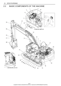
Specification dimension drawings, working range diagrams, the machine specification tables for both the PC200/PC200LC group and the PC220/PC220LC group, component weight tables, and the table of fuel, coolant and lubricants with every refill capacity (engine oil pan, swing machinery case, final drive case, damper case, hydraulic system, fuel tank, cooling system).
Structure, Function and Maintenance Standard
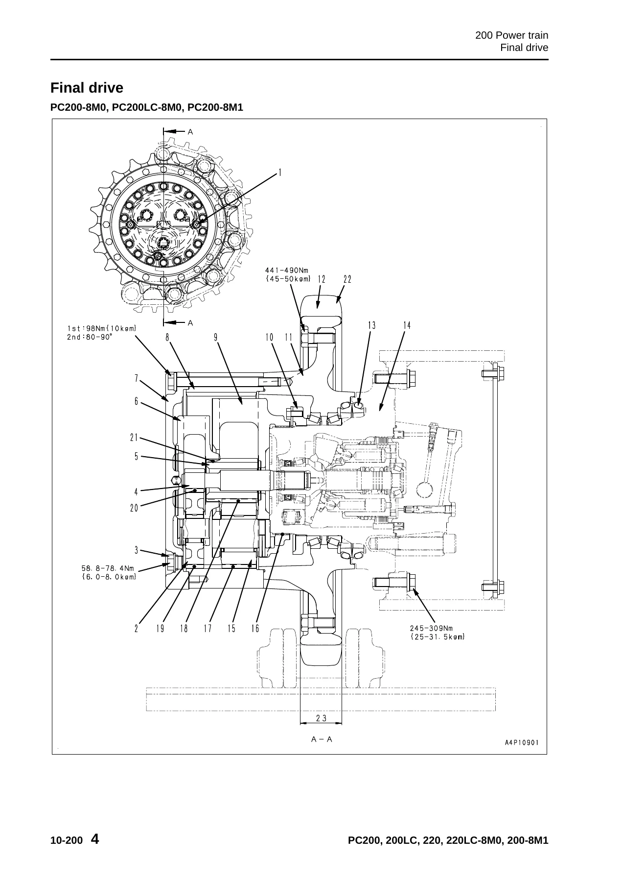
Explains the construction and operation of each assembly and gives the wear limits and clearances used to decide whether a part is reusable. The engine and cooling system section covers the damper assembly, radiator, oil cooler, aftercooler and fuel cooler. The power train section takes apart the final drive (with tooth counts, reduction ratio and backlash limits), swing machinery and swing circle. The undercarriage and frame section covers the track frame and recoil spring, idler, carrier roller, track roller and track shoe. The hydraulic system is spread across three parts — hydraulic equipment layout and hydraulic tank in Part 1, the control valve and CLSS principle in Part 2, and the swing motor, travel motor, PPC valves, service PPC valve, solenoid valves, accumulators, return oil filter and cylinders in Part 3. The electrical system covers engine control, the electrical control system, the machine monitor system, sensors, the KOMTRAX system and the breaker filter clogging detection system.
Standard Value Table
The benchmark table for both engine and chassis. Engine-side: high and low idle speeds, rated speed, intake (boost) pressure, exhaust gas colour, valve clearance, compression pressure, blowby, engine oil pressure, oil temperature, fan belt tension and air conditioner compressor belt tension. Chassis-side: control lever travel and play, operating forces, unload pressure, relief pressures for boom, arm, bucket, swing and travel, control circuit source pressure, LS differential pressure, swing and travel performance, hydraulic drift, leakage amounts, work equipment cycle times and time lag. Both standard new-machine values and judgement criteria are given.
Testing and Adjusting
Tools and special tool sketches first, then the procedures themselves: engine speed, intake air pressure (boost pressure), exhaust gas colour, valve clearance, compression pressure, blowby, engine oil pressure, fuel system handling and residual pressure release, fuel pressure testing, reduced cylinder mode, no-injection cranking, fuel discharge and return and leak rates, air bleeding, fuel circuit leak testing, controller high voltage handling, air conditioner compressor belt tension, alternator belt replacement, swing circle bearing clearance, track tension, oil pressure testing and adjustment for work equipment, swing, travel and pump PC and LS control circuits, solenoid valve and PPC valve output pressure, PPC valve play adjustment, hydraulic drift diagnosis, oil leakage testing, air bleeding, cab tipping stopper, mirrors and rear view camera angle.
Troubleshooting
The largest part of the manual. It starts with the failure code table and fuse locations, then the general troubleshooting information, connector and wiring tables, T-branch box and T-branch adapter lists. Failure code troubleshooting is spread across five parts, covering air conditioner codes, engine codes (CA-series), pump and monitor codes (D-series), pressure sensor codes (DH-series), and solenoid codes (DW-series and DX-series). The E-mode section handles electrical system symptoms like engine no-start, preheating, monitor display, gauges, working mode, travel speed, alarm buzzer, wiper, camera and KOMTRAX. The H-mode section handles hydraulic and mechanical symptoms — slow or weak operation, unusual noise, boom/arm/bucket speed and power, hydraulic drift, travel deviation, swing performance and attachment circuit problems. The S-mode section handles engine symptoms from startability through oil consumption, coolant temperature and vibration.
Disassembly and Assembly
Step-by-step removal, installation, disassembly and assembly for the fuel supply pump, fuel injectors, front and rear engine oil seals, cylinder head, radiator, hydraulic oil cooler, aftercooler, fuel cooler and the complete engine and hydraulic pump assembly. On the power train side: final drive, swing motor and swing machinery, and swing circle. Undercarriage and frame: carrier roller, track roller, idler and idler cushion, sprocket, track assembly separation and connection, revolving frame and counterweight. Hydraulic system: center swivel joint, hydraulic tank, control valve, hydraulic pump and its input shaft oil seal, work equipment PPC valve, travel PPC valve and work equipment cylinders. Work equipment, cab and its attachments, and electrical components are also covered. Special tool lists, coating material lists, torque values and component weights accompany each procedure.
Appendix — Air Conditioner
Refrigerant precautions, the air conditioner unit layout, refrigeration cycle explanation, controller, compressor, condenser and modulator, sensors, and the full testing and troubleshooting procedure including self-diagnosis, vent changeover testing, sunlight sensor, dual pressure switch, relays and all air conditioner failure codes from 879AKA through 879GKX. Compressor oil handling and desiccant replacement are included.
Diagrams and Drawings
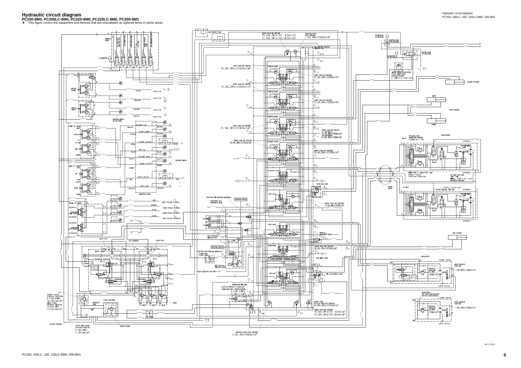
Hydraulic circuit diagrams including the base circuit, boom raise, swing left and the combined boom raise plus swing left operation, with the symbol legend. Electrical circuit diagrams across five sheets and the full wiring harness diagram in ten sheets covering every connector, junction, relay, diode and ground point.
What This Komatsu Hydraulic Excavator Shop Manual Enables You to Do
With this manual on hand, a failure code on the machine monitor is no longer a dead end. You look up the code in the troubleshooting section, follow the checks in order, and find the actual cause — whether it is a pressure sensor, a solenoid, a wiring harness fault, a pump that has drifted out of specification, or a mechanical failure inside the final drive. The same manual supports the repair itself: the disassembly and assembly procedures give you the order, the special tools, the tightening torques and the component weights, and the structure and function chapter explains what you are looking at when the assembly is on the bench.
The value of having the exact Komatsu specification is not theoretical. Hydraulic pressures that are set too high or too low damage pumps and cylinders. Valve clearances that are wrong affect combustion and can burn valves. Fasteners that are not tightened to the specified torque fail under load. The standard value table in this manual is what you compare against so the machine goes back to work correctly and stays there.
IMAGES PREVIEW
Delivery is instant. The PDF is available for download immediately after payment — no shipping, no waiting. It opens on any device, can be printed for the workshop and stays available for as long as you keep the file. One purchase covers all five models.

Reviews
There are no reviews yet.