
Komatsu PC2000-8 Hydraulic Excavator Shop Manual SEN01607-02 – Full Service & Repair PDF
Original price was: $49.95.$29.95Current price is: $29.95.
The complete Komatsu PC2000-8 Hydraulic Excavator Shop Manual (SEN01607-02) covering specification, structure and function, standard value tables, testing and adjusting, troubleshooting, disassembly and assembly, plus hydraulic and electrical circuit diagrams for serial numbers 20001 and up.
Description
Komatsu PC2000-8 Hydraulic Excavator Shop Manual – SEN01607-02
The Komatsu PC2000-8 Hydraulic Excavator Shop Manual (document number SEN01607-02) is the complete workshop reference for the PC2000-8 mining-class hydraulic excavator, serial number 20001 and up. This full service and repair PDF covers every documented system on the machine: the SAA12V140E-3 diesel engine and cooling package, the PTO and power train, undercarriage and frame, the complete hydraulic system across three sections, work equipment, cab and its attachments, and the electrical system with engine control, monitor, sensors, and the ORBCOMM terminal. Everything a technician needs to diagnose, test, adjust, disassemble, and reassemble the PC2000-8 is contained in this single document.
File Details
- Manual Type: Shop Manual (Service & Repair)
- Brand: Komatsu
- Model: PC2000-8 Hydraulic Excavator
- Serial Number Range: 20001 and up
- Engine: SAA12V140E-3
- Document Number: SEN01607-02
- Language: English
- Publication: 2006, Printed in Japan
- File Format: PDF
- Page Count: 1,348 pages
Chapters Covered
- 00 Index and foreword – composition of shop manual, safety notice, how to read the shop manual, maintenance standard terminology, handling electric and hydraulic components, electric wire codes, standard tightening torque tables, conversion tables
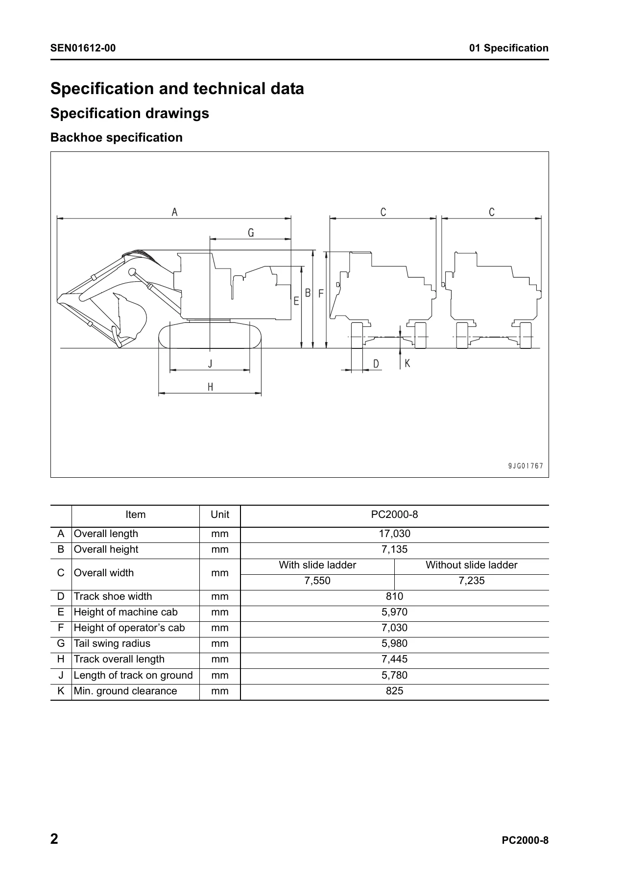
- 01 Specification – specification drawings, full specifications, weight table, fuel / coolant / lubricant table
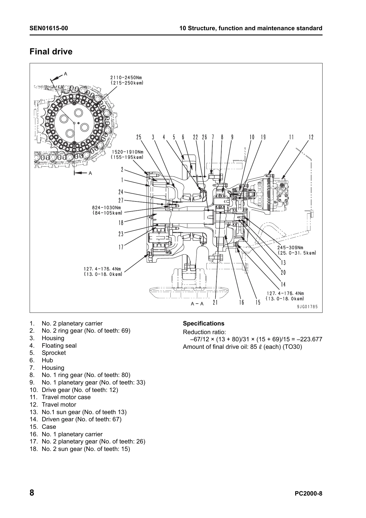
- 10 Structure, function and maintenance standard – Engine and cooling system; Power train (PTO, swing machinery, swing circle, final drive, sprocket); Undercarriage and frame (track frame, idler, carrier roller, track roller, track shoe, HIC system); Hydraulic system Part 1 (piping, tank, oil cooler, line / pilot / return / motor drain / pump drain filters, accumulator, travel junction valve, solenoid valve, hydraulic cylinder, greasing system, center swivel joint); Hydraulic system Part 2 (control valve, electronic OLSS, swing motor, cooling fan motor and pump); Hydraulic system Part 3 (travel motor, hydraulic pump, PPC valve, variable back pressure valve, suction selector valve, PPC cut-off valve); Work equipment; Cab and its attachments; Electrical system (engine control, electrical control system, monitor system, sensors, ORBCOMM terminal)
- 20 Standard value table – standard service values for testing, adjusting and troubleshooting; standard service value table for chassis
- 30 Testing and adjusting, Part 1 – tools, engine speed, air boost pressure, exhaust temperature, exhaust color, valve clearance, compression pressure, blow-by pressure, engine oil pressure, fuel system handling, fuel pressure, pressure limiter and injector return, air bleeding (including low-grade fuel specification), fuel leakage test, air conditioner belt
- 30 Testing and adjusting, Part 2 – swing circle bearing clearance, HIC circuit pressure relief, gas filling and oil supply, track shoe tension, work equipment / swing / travel circuit oil pressures, control circuit pressure, main pump control signal, fan speed, fan pump EPC current and pressure, PPC valve output pressure, solenoid outlet pressure, PPC valve adjustment, travel deviation, work equipment hydraulic drift cause, oil leakage, residual pressure, air bleeding from all components and PPC circuit, auto grease system, mirror adjustment
- 30 Testing and adjusting, Part 3 – special functions of machine monitor, handling controller voltage circuit
- 30 Testing and adjusting, Part 4 – VHMS controller initial setting, precautions for VHMS controller replacement, electrical system troubleshooting preparation, PM-clinic service, measurement procedures
- 40 Troubleshooting – failure code table and fuse locations, general information on troubleshooting, troubleshooting by failure code Parts 1 through 7, troubleshooting of electrical system (E-mode), troubleshooting of hydraulic and mechanical system (H-mode), troubleshooting of mechanical system (S-mode)
- 50 Disassembly and assembly – general information, special tools, engine and cooling system (12V140E-3), engine (12V140E-3), power train, undercarriage and frame, hydraulic system, work equipment, cab and its attachments, electrical system
- 90 Diagrams and drawings – hydraulic circuit diagram, electrical circuit diagram (1/2 and 2/2), connector arrangement diagram
Across its 1,348 pages, this Komatsu PC2000-8 shop manual gives a Komatsu-trained or independent technician the full manufacturer workflow for the machine. Structure, function and maintenance standard sections explain how each component is built and what its service limits are. The standard value table chapter provides the baseline numbers used to judge new-machine condition versus repair criteria. Testing and adjusting covers every measurement a shop needs to perform – from boost pressure and valve clearance to PPC output pressures and electronic OLSS differential-pressure sensor voltages – and pairs them with the adjustment procedure. Disassembly and assembly then walks through removal, inspection, and reassembly of the major assemblies with torque values, coating materials, and weight data included throughout.
What This Shop Manual Enables You To Do
This is not a summary or an operator’s booklet. It is the workshop manual used to run a PC2000-8 through its full service life. With it on hand you can:
- Read and act on machine monitor failure codes and user codes by following the exact troubleshooting chart for each one.
- Diagnose hydraulic faults by measuring and interpreting pump EPC currents, jet sensor differential pressures, main relief and safety valve set pressures, and PPC valve outputs against the standard value table.
- Pull, disassemble, and reassemble the SAA12V140E-3 engine, cylinder heads, fuel injectors, high-pressure fuel supply pump, and engine front and rear seals.
- Service the PTO, swing machinery, swing circle, final drive, idler, track roller, and carrier roller with correct clearances, shim selections, and press-fit dimensions.
- Test, adjust, and repair the work equipment PPC valves, travel PPC valves, and hydraulic cylinder assemblies including piston ring expander use and cylinder head packings.
- Trace electrical circuits using the connector arrangement diagram and the electrical circuit diagrams (1/2 and 2/2) shipped with the manual.
- Perform VHMS controller initial setting, quick PM clinic, and snapshot functions for fleet reporting on ORBCOMM-equipped machines.
Who This Komatsu PC2000-8 Service Manual Is For
This Komatsu PC2000-8 service and repair PDF is written for the working technician, fleet maintenance planner, and heavy equipment workshop supporting the PC2000-8 excavator. The depth of the testing and adjusting and troubleshooting sections makes it suitable for shops performing scheduled PM-clinic inspections as well as for field diagnostics of intermittent hydraulic or electrical faults. Because the manual covers serial number 20001 and up, it applies to the full production run of this machine.
Why Correct Procedures and Specs Matter on a Machine This Size
The PC2000-8 is a 200-tonne-class hydraulic excavator with a 12.0 m³ bucket, a 728 kW (976 HP) SAA12V140E-3 engine producing 4,510 Nm of maximum torque, 29.4 MPa main relief pressure, and an 85-litre final drive oil capacity per side. Bolts on this machine are torqued in the hundreds to thousands of Nm – the revolving frame mounting bolts alone take 2,452 to 3,040 Nm. Clearances are measured in hundredths of a millimetre on pins and bushings. High-pressure common rail fuel lines and sleeve nuts must not be reused if they show a taper seal defect. Guessing torque or using the wrong shim can fail the assembly on the first shift. Having the actual Komatsu specification in front of you is what separates a working repair from a comeback.
IMAGES PREVIEW
Instant PDF Delivery – No Shipping, No Waiting
The Komatsu PC2000-8 Hydraulic Excavator Shop Manual SEN01607-02 is delivered instantly as a PDF download after payment. There is no physical shipment, no waiting for a book to arrive, and no risk of a damaged or out-of-print copy. Open it on a laptop in the workshop, on a tablet in the cab, or print the specific pages you need for a job and keep them at the machine. The layout mirrors the original Komatsu manual so chapters, form numbers, and content order match what a factory-trained technician expects.
Reviews
There are no reviews yet.