Komatsu PC200LC-7L PC220LC-7L Hydraulic Excavator Shop Manual – Chassis Repair PDF
$44.95 Original price was: $44.95.$27.95Current price is: $27.95.
Complete Komatsu chassis shop manual for PC200LC-7L and PC220LC-7L hydraulic excavators (serial A86001 and up). Covers structure and function, testing and adjusting, troubleshooting, and full disassembly and assembly procedures for the SAA6D102E-2 engine, hydraulic pump, control valve, swing and travel motors, final drive, undercarriage, work equipment, and electrical system.
Description
Komatsu PC200LC-7L PC220LC-7L Chassis Shop Manual
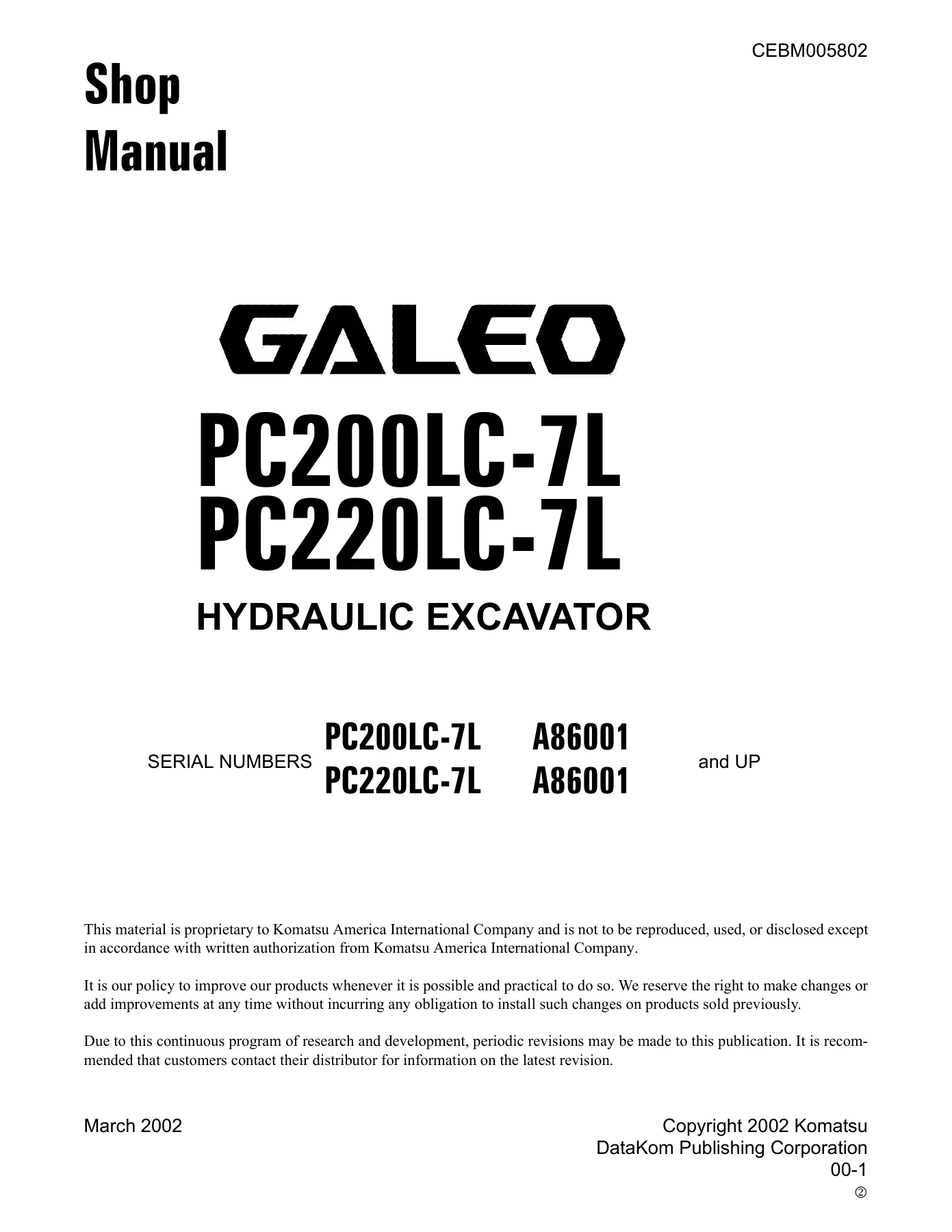
This Komatsu PC200LC-7L PC220LC-7L hydraulic excavator shop manual is the chassis-volume workshop reference for the -7L series machines, issued under form number CEBM005802 in March 2002. It covers both the PC200LC-7L and PC220LC-7L from serial number A86001 upward, and it is the same technical reference Komatsu distributors use when diagnosing, adjusting, and rebuilding these excavators in the service bay.
Where most generic excavator guides stop at routine maintenance, this volume takes the technician the whole way through: how each system is built, how it is supposed to behave, how to test and adjust it, how to isolate faults, and how to pull it apart and put it back together to the correct clearances and torques.
File Details
- Manual type: Chassis Shop Manual (service / repair)
- Brand: Komatsu
- Models covered: PC200LC-7L, PC220LC-7L
- Serial number range: A86001 and up
- Document number: CEBM005802
- Publication date: March 2002
- Language: English
- Page count: 638 pages
- File format: PDF
Chapters Covered
The manual is organised into five top-level sections, each split into component groups:
- 01 GENERAL
- Specification dimension drawings
- Dimensions and working ranges
- Machine specifications
- Weight table
- Fuel, coolant and lubricants
- Standard tightening torques
- Electric wire code
- Conversion tables
- 10 STRUCTURE, FUNCTION AND MAINTENANCE STANDARD
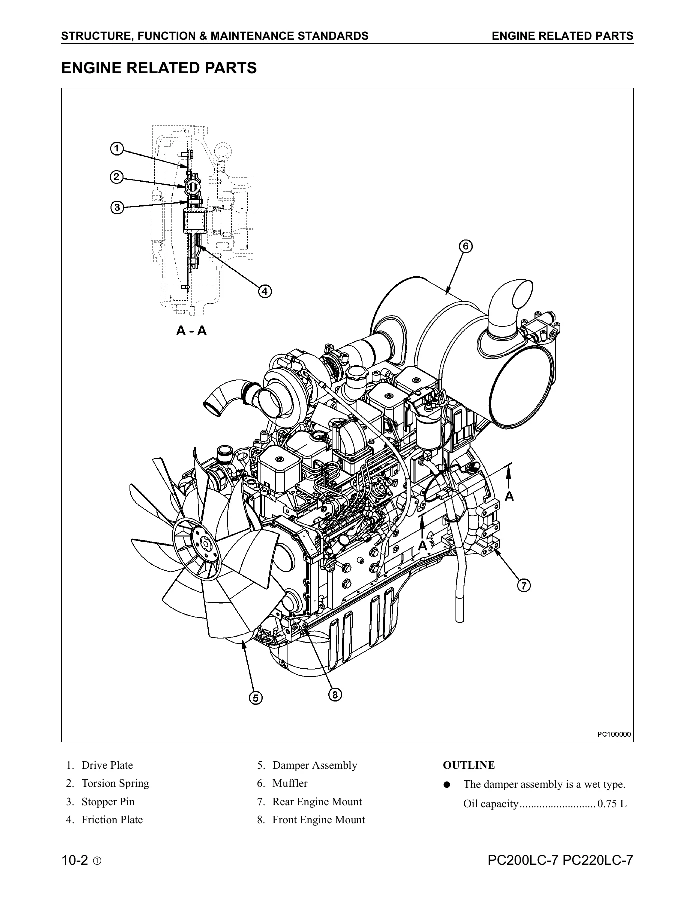
- Engine, damper and cooling system
- Power train layout
- Final drive and travel motor (HMV110ADT-2)
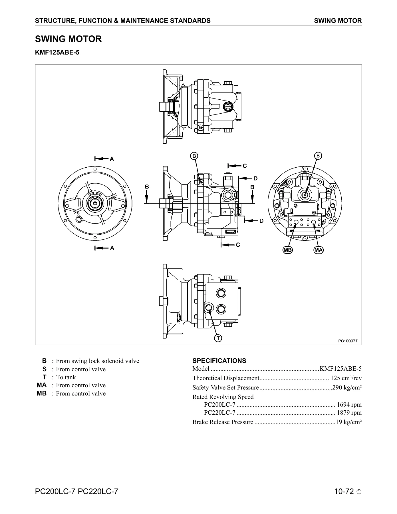
- Swing motor (KMF125ABE-5) and swing machinery
- Swing circle
- Undercarriage: idler, carrier roller, track roller, track chain and shoe
- Hydraulic pump (HPV95+95) β PC valve, LS valve, PC-EPC valve
- CLSS closed-centre load sensing system
- Main control valve, pressure compensation, relief and safety valves
- Self pressure reducing valve
- Boom drift prevention valve, lift check valve
- PPC valves (work equipment, travel)
- Solenoid valve assembly
- Accumulator and hydraulic filter
- Electronic control system, engine throttle and pump controller
- Monitor panel, sensors and switches
- Air conditioner
- 20 TESTING, ADJUSTING AND TROUBLESHOOTING
- Standard value tables (engine and chassis)
- Engine rpm, exhaust gas colour, valve clearance, compression pressure
- Blow-by pressure, fuel injection timing, engine oil pressure
- Engine speed sensor, air conditioner belt
- Swing circle bearings, track shoe tension
- Equipment, swing and travel pressures
- Control circuit, pump PC and pump LS control circuit pressures
- Solenoid valve, PPC valve output pressures
- Work equipment drift, oil leakage, bleeding air
- Multi monitor panel functions and service menu
- Electrical system service codes (E mode) and mechanical system failure codes (H mode)
- Circuit diagram by system and connector tables
Complete PDF Bookmark TreeComplete Bookmarks
The complete bookmarks in the βKomatsu PC200LC-7L PC220LC-7L Hydraulic Excavator Shop Manual – Chassis Repair PDFβ are as follows:
MAIN MENUCOVERp. 1CONTENTSp. 2+FOREWORDp. 12
+SAFETYp. 12
+SAFETY NOTICEp. 12
IMPORTANT SAFETY NOTICEp. 12GENERAL PRECAUTIONSp. 12PREPARATIONS FOR WORKp. 12PRECAUTIONS DURING WORKp. 12GENERALp. 14+HOW TO READ THE SHOP MANUALp. 15
VOLUMESp. 15DISTRIBUTION AND UPDATINGp. 15FILING METHODp. 15REVISED EDITION MARKp. 15REVISIONSp. 15SYMBOLSp. 15+HOISTING INSTRUCTIONSp. 16
HOISTINGp. 16WIRE ROPESp. 16COATING MATERIALSp. 17+STANDARD TIGHTENING TORQUEp. 19
STANDARD TIGHTENING TORQUE OF BOLTS AND NUTSp. 19TIGHTENING TORQUE OF HOSE NUTSp. 20TIGHTENING TORQUE OF SPLIT FLANGE BOLTSp. 20TIGHTENING TORQUE FOR FLARED NUTSp. 20+ELECTRIC WIRE CODEp. 21
CLASSIFICATION BY THICKNESSp. 21CLASSIFICATION BY COLOR AND CODEp. 21+CONVERSION TABLESp. 22
METHOD OF USING THE CONVERSION TABLEp. 22+01 GENERALp. 28
+SPECIFICATION DIMENSION DRAWINGSp. 29
+PC200LC-7L, PC220LC-7Lp. 29
DIMENSIONSp. 29WORKING RANGESp. 30SPECIFICATIONSp. 31WEIGHT TABLEp. 33FUEL, COOLANT AND LUBRICANTSp. 35+10 STRUCTURE, FUNCTION & MAINTENANCE STANDARDSp. 36
ENGINE RELATED PARTSp. 37RADIATOR, OIL COOLER AND AFTERCOOLERp. 38POWER TRAINp. 39FINAL DRIVEp. 40SWING MACHINERYp. 43SWING CIRCLEp. 47UNDERCARRIAGEp. 49IDLERp. 51CARRIER ROLLERp. 53TRACK ROLLERp. 54TRACK CHAIN AND SHOESp. 55HYDRAULIC EQUIPMENTp. 59HYDRAULIC TANKp. 61HYDRAULIC PUMPp. 62MAIN CONTROL VALVEp. 83MAIN RELIEF VALVEp. 99VARIABLE PRESSURE COMPENSATION VALVEp. 100CLSSp. 101SELF PRESSURE REDUCING VALVEp. 104SWING MOTORp. 107REVERSE PREVENTION VALVEp. 112CENTER SWIVEL JOINTp. 114TRAVEL MOTORp. 115TRAVEL JUNCTION VALVEp. 123TRAVEL PPC SHUTTLE VALVEp. 125VALVE CONTROLp. 127EQUIPMENT PPC VALVEp. 129TRAVEL PPC VALVEp. 133SERVICE PPC VALVEp. 140SOLENOID VALVEp. 143PPC ACCUMULATORp. 145BREAKER RETURN OIL FILTERp. 146BOOM DRIFT PREVENTION VALVEp. 147LIFT CHECK VALVEp. 151ATTACHMENT SELECTOR VALVEp. 152EQUIPMENT CYLINDERSp. 155WORK EQUIPMENTp. 159AIR CONDITIONERp. 167ENGINE CONTROLSp. 168ELECTRONIC CONTROL SYSTEMp. 174MULTI MONITOR SYSTEMp. 196SENSORSp. 214+20 TESTING, ADJUSTING AND TROUBLESHOOTINGp. 216
+STANDARD VALUE TABLESp. 217
ENGINE PARTSp. 217CHASSIS PARTSp. 218FLOW CONTROL CHARACTERISTIC OF PC VALVEp. 227herep. 501+TESTING AND ADJUSTINGp. 228
TOOLS FOR TESTINGp. 229ENGINE RPMp. 230EXHAUST GAS COLORp. 232VALVE CLEARANCEp. 233ENGINE COMPRESSION PRESSUREp. 235BLOW BY PRESSUREp. 236FUEL INJECTION TIMINGp. 237ENGINE OIL PRESSUREp. 239ENGINE SPEED SENSORp. 240AIR CONDITIONER BELTp. 241ENGINE CONTROL FAILUREp. 242SWING CIRCLE BEARINGSp. 243TRACK SHOE TENSIONp. 244EQUIPMENT, SWING AND TRAVEL PRESSURESp. 245CONTROL CIRCUIT OIL PRESSUREp. 249PUMP PC CONTROL CIRCUIT PRESSUREp. 250PUMP LS CONTROL CIRCUIT PRESSUREp. 253SOLENOID VALVE OUTPUT PRESSUREp. 258PPC VALVE OUTPUT PRESSUREp. 261EQUIPMENT AND SWING PPC VALVEp. 262WORK EQUIPMENT DRIFTp. 263RELEASE REMAINING PRESSUREp. 265OIL LEAKAGE AMOUNTp. 266BLEEDING AIRp. 269INSPECTION PROCEDURES FOR DIODEp. 271MULTI MONITOR PANELp. 272ELECTRICAL SYSTEM PREPARATIONSp. 295+TROUBLESHOOTINGp. 306
TROUBLESHOOTING POINTS TO REMEMBERp. 307SEQUENCE OF EVENTSp. 309+MAINTENANCE POINTS TO REMEMBERp. 310
WHEN HANDLING ELECTRIC EQUIPMENTp. 310WHEN TROUBLESHOOTING ELECTRIC CIRCUITSp. 314WHEN HANDLING HYDRAULIC EQUIPMENTp. 315CHECKS BEFORE TROUBLESHOOTINGp. 317+CLASSIFICATION AND STEPS FOR TROUBLESHOOTINGp. 318
CLASSIFICATION OF TROUBLESHOOTINGp. 318STEPS FOR TROUBLESHOOTINGp. 318FAILURE LOOKING PHENOMENON AND TROUBLESHOOTING NO.p. 319+ELECTRICAL CIRCUIT DIAGRAM BY SYSTEMp. 322
CONNECTOR TABLEp. 322CONNECTOR LOCATIONp. 327MONITOR PANEL SYSTEM CIRCUIT DIAGRAM (M CIRCUIT)p. 333+TROUBLESHOOTING ELECTRICAL SYSTEM SERVICE CODE AND MECHANICAL SYSTEM FAILURE CODEp. 336
INFORMATION CONTAINED IN TESTING TABLEp. 337E101 – ABNORMAL DATA IN ERROR HISTORYp. 339E112 – SHORT IN NORMAL ROTATION SYSTEM OF WIPER MOTOR DRIVEp. 341E113 – SHORT IN REVERSE ROTATION SYSTEM OF WIPER MOTOR DRIVEp. 343E114 – SHORT IN WINDOW WASHER SYSTEMp. 345E115 – ABNORMAL WIPER MOTOR MOTIONp. 347E116 – ABNORMALITY IN RETRACTING WIPER ARMp. 349E201 – SHORT IN TRAVEL INTERLOCKING SOLENOIDp. 351E203 – SHORT IN SWING AND PARKING BRAKE SOLENOID – IN GOVERNOR PUMP CONTROLLER SYSTEMp. 353E204 – SHORT IN MERGE/DIVIDE SOLENOIDp. 355E205 – SHORT IN 2 STAGE RELIEF SOLENOIDp. 357E206 – SHORT IN TRAVEL SPEED SHIFTING SOLENOIDp. 359E211 – DISCONNECTION IN TRAVEL INTERLOCKING SOLENOIDp. 361E213 – DISCONNECTION IN SWING PARKING BRAKE SOLENOIDp. 363E214 – DISCONNECTION OF MERGE/DIVIDE SOLENOIDp. 365E215 – DISCONNECTION IN 2 STAGE RELIEF SOLENOIDp. 367E216 – DISCONNECTION IN TRAVEL SPEED SHIFTING SOLENOIDp. 369E217 – ABNORMALITY IN INPUTTING MODEL CODE – PC200LC-7p. 371E217- ABNORMALITY IN INPUTTING MODEL CODE – PC220LC-7p. 373E218 – DISCONNECTION OF S-NET SIGNALp. 375E222 – SHORT IN LS-EPC SOLENOIDp. 377E223 – DISCONNECTION IN LS-EPC SOLENOID SYSTEMp. 378E224 – ABNORMALITY IN F PUMP PRESSURE SENSORp. 379E225 – ABNORMALITY IN R PUMP PRESSURE SENSORp. 381E226 – ABNORMALITY IN PRESSURE SENSOR POWER SOURCEp. 383E227 – ABNORMALITY IN ENGINE RPM SENSOR IN GOVERNOR PUMP CONTROLLERp. 385E228 – SHORT IN ATTACHMENT RETURN SWITCHING RELAYp. 386E232 – SHORT IN PC-EPC SOLENOIDp. 387E233 – DISCONNECTION IN PC-EPC SOLENOID SYSTEMp. 389E238 – DISCONNECTION IN ATTACHMENT RETURN SWITCH RELAYp. 391E245 – SHORT IN ATTACHMENT OIL FLOW RATE ADJUSTING EPCp. 393E246 – DISCONNECTION IN ATTACHMENT OIL FLOW RATE ADJUSTING EPCp. 394E256 – INCORRECT NONVOLATILE MEMORY DATAp. 395E306 – ABNORMALITY IN GOVERNOR POTENTIOMETERp. 397E308 – ABNORMALITY IN FUEL DIALp. 399E315 – SHORT IN BATTERY RELAYp. 401E316 – STEP OUT IN GOVERNOR MOTORp. 403E317 – DISCONNECTION IN GOVERNOR MOTOR PHASE A AND Bp. 405E318 – SHORT IN GOVERNOR MOTOR PHASE A AND PHASE Bp. 407E501 – MODEL SELECTION FUNCTION NOT PROVIDED YETp. 409E502 – MODEL SELECTING SIGNAL FAULTp. 410A000N1 – OUT OF RATE ENGINE ROTATION AT HIGH IDLEp. 411A000N2 – OUT OF RATE ENGINE ROTATION AT LOW IDLEp. 412AA10NX – AIR CLEANER CLOGGINGp. 413AB00KE – ABNORMALLY LOWERED CHARGING VOLTAGEp. 415B@BAZG – ABNORMALLY LOWERED ENGINE OIL PRESSUREp. 417B@BAZK – ABNORMALLY LOWERED ENGINE OIL LEVELp. 419B@BCNS – ENGINE COOLANT OVERHEATINGp. 421B@BCZK – ABNORMALLY LOWERED RADIATOR COOLANT LEVELp. 423B@HANS – HYDRAULIC OIL OVERHEATINGp. 425+TROUBLESHOOTING ELECTRICAL SYSTEM – E MODEp. 427
INFORMATION CONTAINED IN TESTING TABLEp. 428E-1 ENGINE DOES NOT START (ENGINE DOES NOT ROTATE)p. 429E-2 ENGINE STOPS WHILE IN OPERATIONp. 432E-3 ENGINE SPEED IS IRREGULAR, OR THERE IS HUNTINGp. 434E-4 ENGINE DOES NOT STOPp. 436E-5 AUTO DECELERATOR DOES NOT WORKp. 438E-6 AUTO ENGINE WARM UP DEVICE DOES NOT WORKp. 439E-7 PREHEATER DOES NOT WORKp. 440E-8 ALL WORK EQUIPMENT, SWING AND TRAVEL DO NOT MOVEp. 442E-9 ONE TOUCH POWER MAX SWITCH DOES NOT WORKp. 444E-10 NO DISPLAY IN MONITOR PANEL AT ALLp. 446E-11 PART OF DISPLAY ON MONITOR PANEL IS MISSINGp. 448E-12 MONITOR PANEL DISPLAYS CONTENTS IRRELEVANT TO THE MODELp. 449E-13 FUEL LEVEL MONITOR RED LAMP LIGHTS UP WHILE ENGINE IS RUNNINGp. 450E-14 ENGINE COOLANT TEMPERATURE GAUGE DOES NOT INDICATE CORRECTLYp. 452E-15 HYDRAULIC OIL TEMPERATURE GAUGE DOES NOT DISPLAY CORRECTLYp. 454E-16 FUEL GAUGE DOES NOT DISPLAY CORRECTLYp. 456E-17 SWING LOCK MONITOR DOES NOT DISPLAY CORRECTLYp. 458E-18 SWING LOCK MONITOR DOES NOT DISPLAY CORRECTLYp. 460E-19 WINDSHIELD WIPER DOES NOT WORKp. 462E-20 ALARM BUZZER CANNOT BE CANCELLEDp. 464E-21 BOOM RAISE IS NOT CORRECTLY DISPLAYED IN MONITOR FUNCTIONp. 466E-22 BOOM LOWER IS NOT CORRECTLY DISPLAYED IN MONITOR FUNCTIONp. 468E-23 ARM DIG IS NOT CORRECTLY DISPLAYED IN MONITOR FUNCTIONp. 470E-24 ARM DUMP IS NOT CORRECTLY DISPLAYED IN MONITOR FUNCTIONp. 472E-25 BUCKET DIG IS NOT CORRECTLY DISPLAYED IN MONITOR FUNCTIONp. 474E-26 BUCKET DUMP IS NOT CORRECTLY DISPLAYED IN MONITOR FUNCTIONp. 476E-27 SWING IS NOT CORRECTLY DISPLAYED IN MONITOR FUNCTIONp. 478E-28 TRAVEL IS NOT CORRECTLY DISPLAYED IN MONITOR FUNCTIONp. 480E-29 TRAVEL DIFFERENTIAL PRESSURE IS NOT CORRECTLY DISPLAYED IN MONITOR FUNCTIONp. 482E-30 SERVICE IS NOT CORRECTLY DISPLAYED IN MONITOR FUNCTIONp. 484E-31 AIR CONDITIONER DOES NOT WORKp. 486E-32 TRAVEL ALARM DOES NOT SOUNDp. 488+TROUBLESHOOTING MECHANICAL SYSTEM – H MODEp. 490
SYSTEM CHART FOR HYDRAULIC AND MECHANICAL SYSTEMSp. 491INFORMATION CONTAINED IN TESTING TABLEp. 493H-1 ALL WORK EQUIPMENT LACK POWER, OR TRAVEL AND SWING SPEED ARE SLOWp. 494H-2 ENGINE SPEED SHARPLY DROPS OR ENGINE STALLSp. 495H-3 NO WORK EQUIPMENT, TRAVEL OR SWING MOVEp. 496H-4 ABNORMAL NOIS IS HEARD FROM AROUND HYDRAULIC PUMPp. 497H-5 AUTO DECELERATOR DOES NOT WORKp. 498H-6 FINE CONTROL MODE DOES NOT FUNCTIONp. 499H-7 BOOM MOVES SLOWLY OR LACKS POWERp. 500H-8 ARM MOVES SLOWLY OR LACKS POWERp. 501H-9 BUCKET MOVES SLOWLY OR LACKS POWERp. 502H-10 WORK EQUIPMENT DOES NOT MOVE IN ITS SINGLE OPERATIONp. 503H-11 WORK EQUIPMENT HAS A BIT TOO FAST HYDRAULIC DRIFTp. 504H-12 WORK EQUIPMENT HAS BIG TIME LAGp. 505H-13 OTHER WORK EQUIPMENT MOVES WHEN RELIEVING SINGLE CIRCUITp. 506H-14 ONE TOUCH POWER MAX SWITCH DOES NOT OPERATEp. 507H-15 IN COMPOUND OPERATION, WORK EQUIPMENT WITH LARGER LOAD MOVES SLOWLYp. 508H-16 IN SWING AND BOOM RAISE OPERATION, BOOM MOVES SLOWLYp. 509H-17 IN SWING AND TRAVEL, TRAVEL SPEED DROPS SHARPLYp. 510H-18 MACHINE SWERVES IN TRAVELp. 511H-19 MACHINE TRAVELS SLOWLYp. 512H-19 MACHINE CANNOT BE EASILY STEERED OR LACKS POWERp. 513H-21 TRAVEL SPEED DOES NOT SHIFT, OR IT IS TOO SLOW OR FASTp. 514H-22 TRACK SHOE DOES NOT TURN (ON ONE SIDE ONLY)p. 515H-23 MACHINE DOES NOT SWINGp. 516H-24 SWING ACCELERATION IS POOR, OR SWING SPEED IS SLOWp. 517H-25 EXCESSIVE OVERRUN WHEN STOPPING SWINGp. 518H-26 THERE IS A BIG SHOCK WHEN STOPPING SWINGp. 519H-27 THERE IS A BIG ABNORMAL NOISE CAUSED WHEN STOPPING SWINGp. 520H-28 SWING NATRUAL DRIFT TOO BIGp. 521till herep. 298+30 DISASSEMBLY AND ASSEMBLYp. 522
METHOD OF USING MANUALp. 526+PRECAUTIONS DURING OPERATIONp. 527
PRECAUTIONS WHEN CARRYING OUT REMOVAL WORKp. 527PRECAUTIONS WHEN CARRYING OUT INSTALLATION WORKp. 528PRECAUTIONS WHEN COMPLETING THE OPERATIONSp. 529OTHER PRECAUTIONSp. 529SPECIAL TOOL LISTp. 530SKETCHES OF SPECIAL TOOLSp. 534+ENGINEp. 535
AFTERCOOLER COREp. 535ALTERNATORp. 535CYLINDER HEADp. 535ENGINE FRONT SEALp. 535ENGINE OIL COOLERp. 535ENGINE REAR SEALp. 535FUEL INJECTION PUMPp. 535NOZZLE HOLDERp. 535STARTING MOTORp. 535THERMOSTATp. 535TURBOCHARGERp. 535WATER PUMPp. 535+RADIATORp. 312
REMOVALp. 536INSTALLATIONp. 537+HYDRAULIC OIL COOLERp. 538
REMOVALp. 538INSTALLATIONp. 539+ENGINE AND HYDRAULIC PUMPSp. 540
REMOVALp. 540INSTALLATIONp. 544+FINAL DRIVEp. 546
REMOVALp. 546INSTALLATIONp. 323DISASSEMBLYp. 548ASSEMBLYp. 325+SWING MOTOR AND SWING MACHINERYp. 556
REMOVALp. 556INSTALLATIONp. 556DISASSEMBLYp. 557ASSEMBLYp. 560+CARRIER ROLLERp. 566
ASSEMBLYp. 566+TRACK ROLLERp. 567
ASSEMBLYp. 567+IDLERp. 568
DISASSEMBLYp. 568ASSEMBLYp. 569+RECOIL SPRINGp. 317
DISASSEMBLYp. 571ASSEMBLYp. 572+SPROCKETp. 573
REMOVALp. 573INSTALLATIONp. 573+TRACK SHOEp. 574
REMOVAL AND EXPANSION TRACK SHOEp. 574INSTALLATION TRACK SHOEp. 575+SWING CIRCLEp. 576
REMOVALp. 576INSTALLATIONp. 577+REVOLVING FRAMEp. 578
REMOVALp. 578INSTALLATIONp. 317+CENTER SWIVAL JOINTp. 581
REMOVALp. 581INSTALLATIONp. 582DISASSEMBLYp. 583ASSEMBLYp. 583+HYDRAULIC TANKp. 584
REMOVALp. 584INSTALLATIONp. 586+CONTROL VALVEp. 587
REMOVALp. 587INSTALLATIONp. 589PROCEDURES FOR REPLACING PRESSURE COMPENSATION VALVE SEALp. 590ASSEMBLYp. 591+HYDRAULIC PUMPp. 592
REMOVALp. 592INSTALLATIONp. 594+INPUT SHAFT – OIL SEALp. 595
REMOVALp. 595INSTALLATIONp. 595+WORK EQUIPMENT PPC VALVEp. 596
ASSEMBLYp. 596+TRAVEL PPC VALVEp. 597
ASSEMBLYp. 597+HYDRAULIC CYLINDERp. 598
DISASSEMBLYp. 598ASSEMBLYp. 601+WORK EQUIPMENTp. 605
REMOVALp. 605INSTALLATIONp. 607+AIR CONDITIONER UNITp. 608
REMOVALp. 608INSTALLATIONp. 611+COUNTERWEIGHTp. 612
REMOVALp. 612INSTALLATIONp. 612+OPERATORβS CABp. 613
REMOVALp. 613INSTALLATIONp. 615+MONITORp. 616
REMOVALp. 616INSTALLATIONp. 616+GOVERNOR PUMP CONTROLLERp. 617
REMOVALp. 617INSTALLATIONp. 617+90 OTHERSp. 618
+ELECTRICALp. 620
CIRCUIT DIAGRAM SHEET 1 (PART 1 OF 3)p. 620CIRCUIT DIAGRAM SHEET 1 (PART 2 OF 3)p. 622CIRCUIT DIAGRAM SHEET 1 (PART 3 OF 3)p. 624CIRCUIT DIAGRAM SHEET 2 (PART 1 OF 1)p. 626CIRCUIT DIAGRAM SHEET 3 (PART 1 OF 2)p. 628CIRCUIT DIAGRAM SHEET 3 (PART 2 OF 2)p. 630CIRCUIT DIAGRAM SHEET 4 (PART 1 OF 2)p. 632CIRCUIT DIAGRAM SHEET 4 (PART 2 OF 2)p. 634 - 30 DISASSEMBLY AND ASSEMBLY
- Radiator, hydraulic oil cooler
- Engine and hydraulic pumps removal and installation
- Final drive disassembly and assembly
- Swing motor and swing machinery
- Carrier roller, track roller, idler, recoil spring
- Sprocket, track shoe, swing circle
- Revolving frame, centre swivel joint, hydraulic tank
- Control valve and pressure compensation valve seal replacement
- Hydraulic pump and input shaft oil seal
- Work equipment PPC valve, travel PPC valve
- Hydraulic cylinders (boom, arm, bucket)
- Work equipment removal and installation
- Air conditioner unit, counterweight, operator’s cab
- Monitor, governor pump controller
- 90 OTHER
- Full electrical circuit diagram sheets (4 sheets)
What This Komatsu Shop Manual Gives You
Read as a whole, this PC200LC-7L and PC220LC-7L chassis shop manual is a full-service reference for the -7L excavator platform. It opens with the machine’s real dimensions, working ranges and weight breakdown, then moves into the structure and function of every major system β pump, valves, motors, cylinders, swing, travel, undercarriage, and the electronic control layer that manages them. From there it hands over the numbers a technician actually works with: standard value tables, pressure and speed tolerances, spool strokes, lever forces, drift limits, leakage allowances, and torque values.
The troubleshooting section is one of the strongest parts of the book. Faults are grouped into display codes (E mode for the electrical system and H mode for the hydraulic and mechanical systems), each with a symptom-to-cause flow, testing reference, and expected reading. This lets you work from a code on the monitor panel down to a specific circuit or component without guessing.
The disassembly and assembly section picks up where diagnosis ends, giving the removal, teardown, inspection, and reassembly sequence for major assemblies, along with special-tool part numbers, tightening torques, and sealant or thread-locker call-outs throughout.
Covered Models and Engine
- PC200LC-7L β operating weight 20,700 kg, bucket capacity 0.8 mΒ³
- PC220LC-7L β operating weight 24,130 kg, bucket capacity 1.0 mΒ³
- Engine: SAA6D102E-2, 4-cycle water-cooled in-line vertical, direct injection, turbocharged, 6 cylinders, 102 x 120 mm bore and stroke, 5.883 L displacement
- Hydraulic pump: HPV95+95 variable displacement twin pump
- Swing motor: KMF125ABE-5 piston type with safety valve and holding brake
- Travel motor: HMV110ADT-2 piston type with brake valve and parking brake
Jobs This Manual Supports
- Diagnosing slow, weak, or drifting boom, arm, and bucket circuits
- Testing and adjusting main relief, PC valve, LS valve, and swing safety valve pressures
- Reading and clearing service codes and failure codes through the monitor panel
- Removing and re-installing the engine and hydraulic pump assembly as a unit
- Rebuilding the final drive, swing motor, swing machinery, and hydraulic cylinders
- Setting track shoe tension and inspecting undercarriage components
- Adjusting lever play and PPC valve output on work equipment and travel circuits
- Tracing faults through the full electrical circuit diagram and connector tables
- Replacing the pressure compensation valve seal and input-shaft oil seal
- Measuring engine compression, blow-by, injection timing, and valve clearance
Why This Manual Matters
The PC200LC-7L and PC220LC-7L are closed-centre load-sensing machines with electronic pump control. Getting them right means using the specified pressures, tolerances, and adjustment procedures rather than rule-of-thumb settings, because the pump, valve, and controller work as a matched system. A torque value or a small clearance taken from the wrong source can put an assembly back together in a way that runs fine for a week and then fails. This manual supplies the numbers, the sequence, and the safety notes for the chassis side of the machine, so repairs are carried out to spec the first time.
IMAGES PREVIEW
Instant PDF Delivery
This Komatsu PC200LC-7L PC220LC-7L shop manual is delivered as a downloadable PDF immediately after purchase β no waiting for shipping, no physical book to handle. Open it on a workshop laptop, tablet, or desktop, search and print the pages you need for the job in front of you, and keep it on hand for the next repair. Whether you are a Komatsu owner doing your own maintenance, an independent mechanic servicing a customer’s -7L machine, or a fleet technician working from a service truck, this chassis shop manual is the reference you want on the shelf and on the screen.
What Our Customers Say
π Related Products
Discover more professional manuals for your equipment

BOMAG BW 211 BW 212 BW 213 D-40 PD-40 Single Drum Roller Service Manual

LiuGong CLG922E Excavator Service Manual 201503001 - Cummins QSB6.7 Workshop Repair Guide

JCB 426, 436, 446 Wheeled Loading Shovel Service Manual PDF


Reviews
There are no reviews yet.