
Komatsu PC210 PC210LC PC240 PC240LC PC240NLC-6K Shop Manual – EEBM000505
Original price was: $44.95.$24.95Current price is: $24.95.
676-page Komatsu shop manual for PC210-6K, PC210LC-6K, PC240-6K, PC240LC-6K and PC240NLC-6K machines from serial number K30001 and up. Covers structure and function, hydraulic and electrical systems, testing and adjusting, troubleshooting, disassembly and assembly, and maintenance standards. Includes S6D102L-1 and SA6D102L-1 engine application references, with detailed engine service directed to the separate 102 Service Engine Shop Manual.
Description
Komatsu PC210 PC210LC PC240 PC240LC PC240NLC-6K Shop Manual – EEBM000505
The Komatsu PC210 PC210LC PC240 PC240LC PC240NLC-6K Shop Manual – EEBM000505 is a detailed service reference for the PC210-6K, PC210LC-6K, PC240-6K, PC240LC-6K and PC240NLC-6K excavator range from serial number K30001 and up. Across 676 pages it combines system descriptions, hydraulic and electrical diagrams, standard values, testing and adjustment procedures, troubleshooting material, component removal and installation instructions, disassembly and assembly procedures, and maintenance-standard data. The manual identifies the S6D102L-1 engine for the PC210/210LC-6 application and the SA6D102L-1 engine for the PC240/240LC-6 application; detailed engine overhaul information is referred to the separate 102 Service Engine Shop Manual.
File Details
- Manual type: Shop Manual
- Brand: Komatsu
- Models: PC210-6K, PC210LC-6K, PC240-6K, PC240LC-6K, PC240NLC-6K
- Serial range: K30001 and up
- Document number: EEBM000505
- Date shown: 02-97
- Language: English
- Page count: 676 pages
- File format: PDF
Machine Systems and Technical Coverage
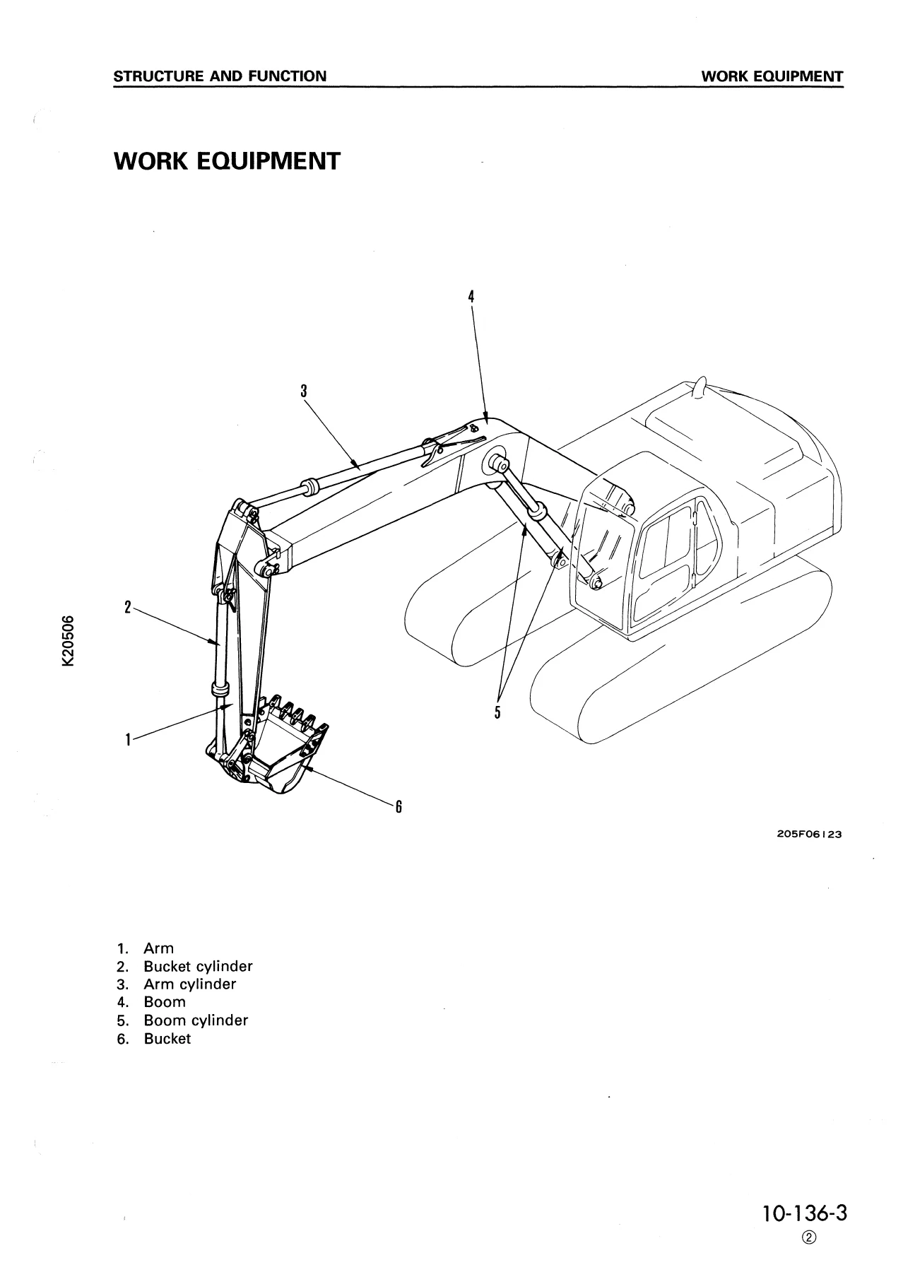
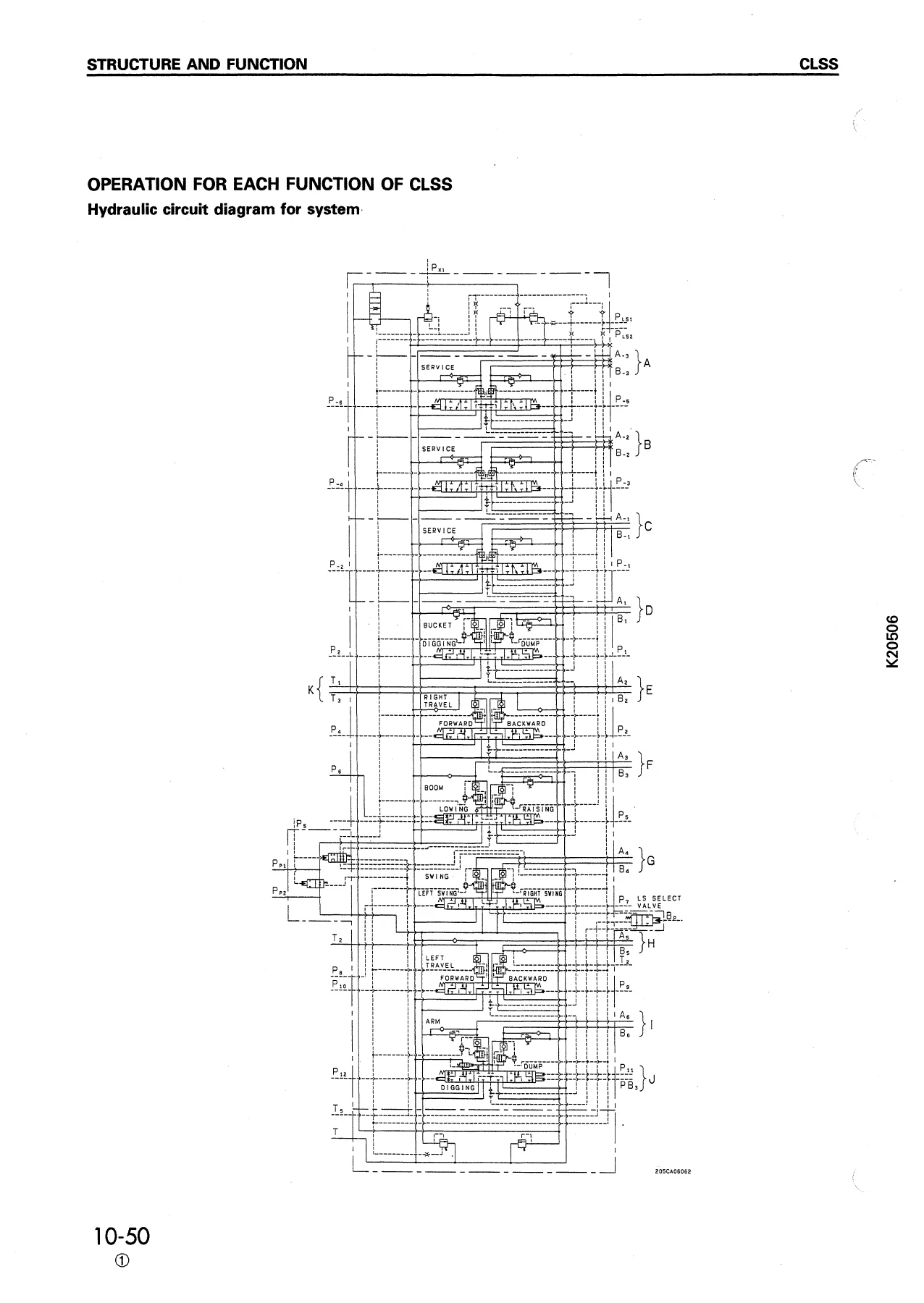
This Komatsu PC210 and PC240 shop manual goes well beyond basic maintenance information. The structure-and-function material explains how major mechanical, hydraulic and electronic assemblies are arranged and how they operate. Coverage includes the power train, final drive, swing circle and swing machinery, track frame and recoil spring, hydraulic tank and pumps, control valve, swing and travel motors, PPC pilot controls, solenoid valves, cylinders, work equipment and machine electronic controls. Hydraulic circuit drawings and the Closed center Load Sensing System (CLSS) material show how pump output, load-sensing pressure, pressure compensation, regeneration circuits and pump merge-divider functions interact during machine operation.
Component pages include sectional drawings and operating explanations for the main hydraulic pump, TVC and LS valves, control pump, control valve, swing motor, travel motor, center swivel joint, PPC valves, safety lock valve, accumulator and travel junction valve. The manual also covers special equipment and protection systems shown in the document, including the additional filter for breaker-equipped machines, overload warning device and boom hose-burst protection valve. Electrical coverage includes wiring diagrams, engine control, electronic control functions, machine monitor circuits, sensors, solenoids and controller input/output information.
Testing, Adjustment and Troubleshooting
A major part of the Komatsu PC210 PC210LC PC240 PC240LC PC240NLC-6K Shop Manual – EEBM000505 is devoted to measurement and diagnosis. Standard-value tables give technicians reference points for engine, chassis, hydraulic and electrical checks. Procedures cover hydraulic pressure measurement in the work-equipment, swing and travel circuits; TVC valve and LS valve output pressure; LS differential pressure; control-pump pressure; EPC and solenoid output pressure; PPC valve output pressure; travel deviation; hydraulic drift; oil leakage; and air bleeding. The electrical standard-value section supplies connector-based inspection information for machine-control components and sensors.
The testing section also includes adjustment and inspection work such as air-conditioner compressor belt tension, engine speed sensor adjustment, governor motor lever stroke, swing-circle bearing clearance and track-shoe tension. Troubleshooting follows the testing material so measured values and circuit behavior can be used to isolate faults rather than relying on guesswork. The manual repeatedly ties diagnostic checks to defined operating conditions such as hydraulic-oil temperature, engine speed and working mode, helping the technician reproduce the conditions under which the stated values apply.
Disassembly, Assembly and Component Removal
For repair work, the manual provides step-by-step removal, installation, disassembly and assembly instructions across the machine. Procedures include the engine and hydraulic-pump assembly, radiator and hydraulic-oil cooler, fuel tank, center swivel joint, final drive, sprocket, swing motor and swing machinery, revolving frame, undercarriage components, hydraulic tank, control pump, main pump, control valve and related hydraulic valves. Later procedures cover pilot-control components, cylinders, work equipment, bucket, arm, boom, operator cab, counterweight, engine throttle controller, pump controller and monitor.
These repair procedures identify precautions, connection points, lifting requirements, refill and air-bleeding steps, tightening values and assembly notes where the manual specifies them. Major hydraulic work is cross-referenced to the testing-and-adjusting section for pressure release and air bleeding. The disassembly and assembly instructions also use illustrations to identify parts and sequence, which is especially useful when servicing planetary gear assemblies, hydraulic valves, cylinders and machine structures.
Chapters Covered
- 10 Structure and Function
- Engine related parts; radiator, oil cooler and aftercooler
- Power train; final drive; swing circle and swing machinery
- Track frame, recoil spring and track shoe
- Hydraulic piping and hydraulic circuit diagrams
- Hydraulic tank and hydraulic pump
- Control valve and CLSS
- Swing motor, center swivel joint and travel motor
- Valve control; work equipment and swing PPC valve; travel and service PPC valves
- Safety lock valve, PPC accumulator and PPC shuttle/travel junction valve
- EPC and solenoid valves; hydraulic cylinders
- Additional breaker filter, overload warning and hose-burst protection systems
- Electrical wiring and control, engine control, electronic control and machine monitor systems
- 20 Testing and Adjusting
- Judgement standard values and electrical-parts standard values
- Air-conditioner compressor belt tension and engine speed sensor adjustment
- Governor motor lever stroke and swing-circle bearing clearance
- Track-shoe tension
- Work-equipment, swing and travel hydraulic pressure testing
- TVC valve output pressure and LS valve output pressure/LS differential
- Control-pump pressure and EPC/solenoid output-pressure testing
- PPC valve output pressure and PPC shuttle-valve testing
- Work-equipment/swing PPC valve and travel-lever adjustment
- Travel deviation, hydraulic drift and oil-leakage testing
- Releasing hydraulic pressure, bleeding air and troubleshooting
- 30 Disassembly and Assembly
- Radiator and hydraulic-oil cooler assemblies
- Engine and hydraulic-pump assembly; damper and fuel tank
- Center swivel joint and final drive
- Sprocket, swing motor and swing machinery
- Revolving frame and undercarriage components
- Track roller, carrier roller and track shoe
- Hydraulic tank, control pump and main pump
- Control valve, pump merge-divider valve, pressure-compensation valve and main relief valve
- TVC/LS valve, LS-control EPC valve and solenoid valves
- Work-equipment/swing PPC and travel PPC valves
- Boom, arm, bucket and hydraulic cylinders
- Work equipment, bucket, arm and boom assemblies
- Operator cab, counterweight, engine throttle controller, pump controller and monitor
- 40 Maintenance Standard
- Final drive, swing machinery and swing circle
- Track frame, recoil spring, idler, carrier roller, track roller and track shoe
- Hydraulic pump and control valve
- Swing motor and travel motor
- Work-equipment/swing PPC valve, travel PPC valve and PPC shuttle/travel junction valve
- EPC/solenoid valve and center swivel joint
- Hydraulic cylinders and work equipment
Taken together, these chapters provide the working information needed to understand system operation, compare measurements with the manual’s standards, trace hydraulic and electrical faults, remove major assemblies, rebuild selected components and check wear or service limits during repair. The combination of circuit diagrams, component drawings, standard values and repair procedures makes this manual useful both for diagnosis before disassembly and for verification during reassembly.
IMAGES PREVIEW
Model-Specific Details Worth Checking
The manual distinguishes between machine variants where dimensions or specifications differ. Track-frame and track-shoe information separates the PC210-6K, PC210LC-6K, PC240-6K, PC240LC-6K and PC240NLC-6K configurations, while hydraulic-cylinder, swing-motor, travel-motor and electronic-control data include model-specific values for PC210 and PC240 applications. This matters when a technician is choosing a standard value, checking a component, setting pressure or comparing wear limits: the correct model column and operating condition should be used rather than assuming one value applies to every version.
The engine note on the manual cover is also important. The machine manual gives engine-related installation and control information, but it directs detailed engine service to the 102 Service Engine Shop Manual. Buyers needing internal engine overhaul procedures should keep that limitation in mind.
Repair With the Correct Procedures and Specifications
The Komatsu PC210 PC210LC PC240 PC240LC PC240NLC-6K Shop Manual – EEBM000505 supports practical work ranging from hydraulic diagnosis and pressure checks to travel and swing troubleshooting, controller and sensor checks, undercarriage service, cylinder work, pump and valve removal, major component disassembly and machine-structure removal. Having the correct procedures, diagrams, tightening information, standard values and maintenance limits in one reference helps reduce avoidable errors during diagnosis and repair.
Delivered as an instant PDF after payment, there is no physical shipping or waiting for a printed book. Open the manual on a computer, tablet or phone, keep it available beside the machine during service, and print the pages you need for the job.
Reviews
There are no reviews yet.