★ TRUSTED BY 321,897+ PROFESSIONALS WORLDWIDE
🏒
Trusted Business
Verified & Licensed
πŸ›‘οΈ
Virus Free Files
100% Safe Downloads
πŸ”’
Secure Payment
SSL Protected
⚑
Instant Delivery
Available Immediately
Sale!

Komatsu PC3000-6 D Hydraulic Mining Shovel Remove & Replace Procedures Manual

Original price was: $44.95.Current price is: $26.95.

655-page Komatsu PC3000-6 / PC 3000-6 D R&R Procedures manual covering major component removal, replacement and adjustment across the diesel engine, PTO, hydraulics, slew drive, undercarriage and backhoe attachment. Includes safety guidance, lifting weights, torque references, tools, capacities, diagrams and service bulletins.

⚑
Instant PDF Download
Available immediately
πŸ’Ύ
Save to Your Device
Download & keep forever
πŸ›‘οΈ
Antivirus Scanned
100% virus-free
🌍
Trusted Worldwide
175,000+ customers

Description

Komatsu PC3000-6 D Remove & Replace Procedures

The Komatsu PC3000-6 D Hydraulic Mining Shovel Remove & Replace Procedures Manual is a detailed component-removal, installation and adjustment reference for the PC3000-6 hydraulic mining shovel. The manual is organized around major machine systems and gives technicians the work sequence, lifting requirements, special tools, fluid handling information, component weights, tightening information and illustrations needed when major assemblies have to be removed, replaced or reinstalled. The foreword identifies the machine as the Hydraulic Excavator PC 3000-6 D, while the cover carries the PC3000-6 model designation.

This is not a short operator guide. Its 655 pages concentrate on heavy repair work across the superstructure, undercarriage and backhoe attachment, supported by safety procedures, lifting data, torque charts, conversion data, tool information and service bulletins. Many operations include preparatory steps, isolation and pressure-relief instructions, component-specific lifting arrangements, hose and wiring disconnection points, replacement precautions and final checks.

File Details

  • Manual type: Remove & Replace Procedures / R & R Procedures
  • Brand: Komatsu
  • Model: PC3000-6; foreword identifies PC 3000-6 D
  • Equipment: Hydraulic Mining Shovel
  • Language: English
  • Page count: 655 pages
  • File format: PDF
  • Version: 2009/1
  • Copyright: 2006

Major Repair Scope

The procedures are built for large-component service rather than routine checks alone. For example, the diesel-engine section identifies the SSA 12 V 159 engine as a 12-cylinder, 4-cycle, water-cooled, direct-injection unit with turbocharging and intercooling, rated at 940 kW (1269 HP) at 1800 rpm. The engine removal and replacement sequence covers coolant and engine-oil draining, fuel and electrical disconnections, roof-frame access, coupling and PTO connections, crane handling, mount installation and specified fastening steps. Separate procedures then address the alternator, batteries, radiator fan, radiator, starter system, Geislinger coupling and engine/PTO mounts.

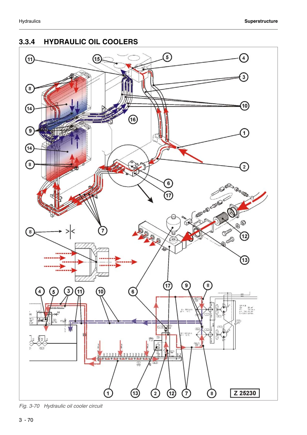
The hydraulic and PTO coverage is particularly extensive. The manual explains the three main-pump arrangement and pump distributor gearbox, then provides dedicated removal and replacement procedures for main pumps 1, 2 and 3, the PTO oil-circulation pump, hydraulic cooler fan drive pump, cooler fan assemblies, oil coolers and cooler frame. It continues through main relief valves, the pilot oil pump, main gate valve, hydraulic oil reservoir, main control valve blocks, service-line relief valves, anti-cavitation valves, throttle check valves and the manifold. Illustrations show hose routes, valve positions, component relationships and lifting arrangements, helping the technician identify what must be disconnected and supported before a component is moved.

Slew-system work is handled as its own group, including the slew gearbox, swing motor, slew parking brake, dynamic slew brake and swing-circle lubrication pinion. The superstructure section also covers lubrication pumps, the CR700 pump controller, operator’s cab and its mounts, front window, operator’s seat, ETM, access ladder, counterweight, separation of the superstructure from the undercarriage, and fuel-tank removal and replacement.

Complete PDF Bookmark Tree

Complete Bookmarks

The complete bookmarks in the β€œKomatsu PC3000-6 D Hydraulic Mining Shovel Remove & Replace Procedures Manual” are as follows:

1 Introductionp. 13
1.1 Contents of the binderp. 14
1.2 Forewordp. 15
1.2.1 Servicep. 16
2 Safetyp. 17
2.1 Safety Instructionsp. 18
2.1.1 Method of using this manualp. 18
2.1.2 General precautionsp. 20
2.1.3 Preparations for workp. 21
2.1.4 Precautions during workp. 22
2.1.5 WARNING OF SPECIAL DANGERSp. 24
2.1.5.1 ELECTRICAL ENERGYp. 24
2.1.5.2 GAS, DUST, STEAM AND SMOKEp. 25
2.1.5.3 HYDRAULIC, AIR CONDITIONING AND PNEUMATIC EQUIPMENTp. 26
2.1.5.4 NOISEp. 26
2.1.5.5 Heatp. 27
2.1.5.6 OIL, GREASE AND OTHER CHEMICAL SUBSTANCESp. 27
2.1.5.7 Heightp. 27
2.1.6 SPECIAL SAFETY EQUIPMENTp. 29
2.1.6.1 SAFETY HARNESS IN CONFORMITY WITH EN 361 (EUROPEAN STANDARD)p. 29
2.1.6.2 INSTRUCTIONS FOR USEp. 31
2.1.6.3 RECOMMENDATIONS FOR USE OF THE HOLDING HOOKS AND HOLD-BACK HOOKS OF THE SAFETY HARNESSp. 33
2.1.6.4 INSTRUCTIONS FOR USEp. 35
2.2 Lifting Gearsp. 36
2.2.1 Wire ropesp. 36
2.2.2 Sling accessoryp. 38
2.2.3 Weight tablesp. 39
2.2.3.1 Superstructurep. 39
2.2.3.2 Undercarriagep. 41
2.2.3.3 Attachmentp. 42
2.3 Torque charts according to DINp. 43
2.3.1 Metric standard threadp. 43
2.3.2 Metric fine threadp. 44
2.3.3 Cummins motor torques – metricp. 45
2.3.4 Cummins motor torques – U.S. Customaryp. 45
2.3.5 Flange connectionsp. 46
2.4 Conversation tablep. 47
2.4.1 Method of using the conversation tablep. 47
2.4.2 Millimeter – Inch & Kilogram – Poundp. 48
2.4.3 Liter – U.S. Gallon & Liter – U.K. Gallonp. 49
2.4.4 KGm – ft.lbp. 50
2.4.5 bar – PSI / PSI – barp. 51
2.4.6 Basic Values in Ohm according to DIN 43 76p. 52
2.4.7 Temperaturep. 53
2.5 Explanation of abbreviationsp. 54
3 Superstructurep. 55
3.1 Diesel Enginep. 56
3.1.1 Removal of the Diesel enginep. 56
3.1.2 Replacement of the Diesel enginep. 62
3.1.3 Engine torque support and engine/PTO mountsp. 64
3.1.3.1 Flexible mountsp. 65
3.1.3.2 Torque supportp. 67
3.1.4 Alternatorp. 68
3.1.4.1 Removal of the alternatorp. 68
3.1.4.2 Replacement of the alternatorp. 70
3.1.5 Batteriesp. 71
3.1.5.1 Removal of the batteriesp. 71
3.1.5.2 Replacement of the batteriesp. 73
3.1.6 Radiator fanp. 74
3.1.6.1 Removal of the radiator fanp. 75
3.1.6.2 Replacement of the radiator fanp. 76
3.1.7 Radiatorp. 77
3.1.7.1 Removal of the Radiatorp. 77
3.1.7.2 Replacement of the radiatorp. 80
3.1.8 Starter systemp. 81
3.1.8.1 Removal of the starter motorp. 81
3.1.8.2 Replacement of the starter motor.p. 82
3.1.9 Geislinger couplingp. 84
3.1.9.1 Removal of the Geislinger couplingp. 86
3.1.9.2 Replacement of the Geislinger couplingp. 88
3.2 PTOp. 89
3.2.1 Main pumpsp. 89
3.2.1.1 Preparatory works for main pump removalp. 91
3.2.1.2 Removal of Main Pump 1p. 95
3.2.1.3 Replacement of main pump 1p. 97
3.2.1.4 Removal of Main Pump 2p. 98
3.2.1.5 Replacement of main pump 2p. 101
3.2.1.6 Removal of Main Pump 3p. 102
3.2.1.7 Replacement of main pump 3p. 105
3.2.2 PTO oil circulation pump (auxiliary pump)p. 106
3.2.2.1 Removal of the oil circulation pump (auxiliary pump)p. 106
3.2.2.2 Replacement of the oil circulation pump (auxiliary pump)p. 107
3.2.3 Pump distributor gearbox (PTO)p. 108
3.2.3.1 Removal of the Pump distributor gearbox (PTO)p. 110
3.2.3.2 Replacement of the Pump distributor gearbox (PTO)p. 113
3.3 Hydraulicsp. 114
3.3.1 Hydraulic cooler fan Drive Pumpp. 114
3.3.1.1 Removal of hydraulic cooler fan drive pumpp. 114
3.3.2 Replacement of hydraulic cooler fan drive pumpp. 116
3.3.3 Hydraulic Cooler Fan Assemblyp. 117
3.3.3.1 Removal of hydraulic cooler fan assemblyp. 117
3.3.3.2 Replacement of hydraulic cooler fan assemblyp. 120
3.3.3.3 Removal of hydraulic cooler Fan and motorp. 122
3.3.3.4 Replacement of hydraulic cooler Fan and motorp. 123
3.3.4 Hydraulic Oil Coolersp. 124
3.3.4.1 Removal of the hydraulic oil coolersp. 127
3.3.4.2 Replacement of the oil hydraulic coolerp. 130
3.3.4.3 Removal of the hydraulic oil cooler framep. 132
3.3.4.4 Replacement of the hydraulic oil cooler framep. 136
3.3.5 Main Relief Valves (MRV)p. 137
3.3.5.1 Removal of the MRVp. 137
3.3.5.2 Replacement of the MRVp. 139
3.3.6 pilot oil pump (Gear pump)p. 140
3.3.6.1 Removal of the pilot oil pumpp. 141
3.3.6.2 Replacement of the pilot oil pumpp. 142
3.3.7 Main Gate Valvep. 143
3.3.7.1 Removal of the main gate valvep. 143
3.3.7.2 Replacement of the main gate valvep. 144
3.3.8 Hydraulic Oil Reservoirp. 146
3.3.8.1 Removal of the hydraulic oil reservoirp. 148
3.3.8.2 Replacement of the hydraulic oil reservoirp. 156
3.3.9 Main Control Valve Blocksp. 159
3.3.9.1 Removal of the main control valve blocksp. 163
3.3.9.2 Replacement of the main control valve blocksp. 167
3.3.10 Service line Relief Valves (SRV)p. 168
3.3.10.1 Removal of SRV on main Control valve blockp. 168
3.3.10.2 Replacement of SRV on main control valve blocksp. 171
3.3.11 Anti-cavitation Valves (ACV)p. 172
3.3.11.1 Removal of ACV on Manifoldp. 173
3.3.11.2 Replacement of ACV on Manifoldp. 177
3.3.11.3 Removal of ACV on main control valve blocksp. 179
3.3.11.4 Replacement of ACV on main control valve blocksp. 181
3.3.12 Throttle check valvesp. 182
3.3.12.1 Removal of throttle check valves)p. 184
3.3.12.2 Replacement of throttle check valvesp. 187
3.3.13 manifoldp. 188
3.3.13.1 Removal of the manifoldp. 188
3.3.13.2 Replacement of the manifoldp. 190
3.3.13.3 Removal of Diffuser on Manifold.p. 191
3.3.13.4 Replacement of Diffuser on Manifoldp. 193
3.4 Slew Drivep. 195
3.4.1 Slew GearBoxp. 196
3.4.1.1 Removal of the slew gearboxp. 197
3.4.1.2 Replacement of the slew gearboxp. 201
3.4.2 Swing Motorp. 203
3.4.2.1 Removal of the swing motorp. 204
3.4.2.2 Replacement of the swing motorp. 206
3.4.3 Slew parking brakep. 207
3.4.3.1 Removal/Disassembly of the parking brakep. 209
3.4.3.2 Replacement/assembly of the slew parking brakep. 212
3.4.4 Dynamic Slew Brakep. 214
3.4.4.1 Removal of the slew service brake valvep. 217
3.4.4.2 Replacement of the slew service brake valvep. 219
3.4.5 Swing circle lubrication pinionp. 220
3.4.5.1 Removal of the lubrication pinion assemblyp. 222
3.4.5.2 Replacement of the lubrication pinion assemblyp. 224
3.5 Lubrication pumpsp. 225
3.5.1 Removal of the Lubrication pumpp. 225
3.5.2 Replacement of the lubricating pumpp. 227
3.6 Pump controller CR700p. 228
3.6.1 Removal of the pump controller CR700p. 228
3.6.2 Replacement of the pump controller CR700p. 229
3.7 Operator’s Cabp. 230
3.7.1 Removal of the operator’s cabp. 232
3.7.2 Replacement of the operator’s cabp. 236
3.7.3 Cab mountsp. 237
3.7.3.1 Removal of the cab mountsp. 237
3.7.3.2 Replacement of the cab mountsp. 238
3.7.4 FRONT WINDOWp. 239
3.7.4.1 Removal of the Front windowp. 239
3.7.4.2 Replacement of the front windowp. 240
3.7.5 Operator’s seatp. 241
3.7.5.1 Removal of the operator’s seatp. 241
3.7.5.2 Replacement of the operator’s seatp. 242
3.7.6 ETMp. 243
3.7.6.1 Removal of the ETMp. 243
3.7.6.2 Replacement of the ETMp. 243
3.7.7 Access Ladderp. 244
3.7.7.1 Removal of access Ladderp. 245
3.7.7.2 Replacement of access ladderp. 247
3.7.7.3 Removal of access ladder cylinderp. 248
3.7.7.4 Replacement of access ladder cylinderp. 249
3.7.8 Removal of the cab basep. 250
3.7.9 Replacement of the cab basep. 252
3.8 CounterWeightp. 254
3.8.1 Removal of the counterweightp. 256
3.8.2 Replacement of the counterweightp. 258
3.9 Superstructure Liftingp. 259
3.9.1 Remove the Superstructure from the Undercarriagep. 259
3.9.2 Install the Superstructure onto the undercarriagep. 263
3.10 Fuel Tankp. 266
3.10.1 Removal of the Fuel tankp. 267
3.10.2 Replacement of the Fuel tankp. 271
4 Undercarriagep. 273
4.1 Travel systemp. 274
4.1.1 Track groupp. 274
4.1.1.1 Substitute the track groupp. 274
4.1.2 Sprocketp. 279
4.1.2.1 Removal of the sprocketp. 279
4.1.2.2 Replacement of the sprocketp. 281
4.1.3 Guide wheelsp. 282
4.1.3.1 Removal of the guide wheel assemblyp. 282
4.1.3.2 Replacement of the guide wheel assemblyp. 283
4.1.4 Track tensioning accumulatorsp. 284
4.1.4.1 Removal of the low pressure accumulatorsp. 284
4.1.4.2 Replacement of the low pressure accumulatorsp. 286
4.1.4.3 Removal of the high pressure accumulatorsp. 287
4.1.4.4 Replacement of the high pressure accumulatorsp. 288
4.1.5 Track tension valve blockp. 289
4.1.5.1 Removal of the track tensioning valve blockp. 289
4.1.5.2 Replacement of the track tensioning valve blockp. 290
4.1.6 Hydraulic hoses of the track tensioning systemp. 291
4.1.6.1 Substitute THE HYDRAULIC HOSESp. 291
4.1.7 Travel brake valve block (overspeed valve)p. 294
4.1.7.1 Removal of the travel brake valve blockp. 295
4.1.7.2 Replacement of the travel brake valve blockp. 296
4.1.8 Track tensioning cylindersp. 297
4.1.8.1 Removal of the track tensioning cylindersp. 297
4.1.8.2 Replacement of the track tensioning cylindersp. 298
4.1.9 Travel motorp. 299
4.1.9.1 Removal of the travel motorsp. 299
4.1.9.2 Replacement of the travel motorsp. 303
4.1.10 travel parking brakep. 304
4.1.10.1 Removal of the travel parking brakep. 306
4.1.10.2 Replacement of the travel parking brakep. 308
4.1.11 Travel gearboxp. 310
4.1.11.1 Removal of the travel gearboxp. 311
4.1.11.2 Replacement of the travel gearboxp. 315
4.1.12 Carrier rollerp. 316
4.1.12.1 Removal of the carrier roller assemblyp. 316
4.1.12.2 Replacement of the carrier roller assemblyp. 318
4.1.13 Track rollerp. 320
4.1.13.1 Removal of the Track roller assemblyp. 320
4.1.13.2 Replacement of the Track roller assemblyp. 321
4.2 Car bodyp. 322
4.2.1 Removal of the car bodyp. 322
4.2.2 Replacement of the car bodyp. 327
4.2.2.1 Tightening torqe for the crawler carrier mounting boltsp. 332
4.2.3 Rotary jointp. 336
4.2.3.1 Removal of the rotary jointp. 338
4.2.3.2 Replacement of the rotary jointp. 341
4.2.4 swing circlep. 342
4.2.4.1 Removal of the swing circlep. 344
4.2.4.2 Replacement of the swing circlep. 346
5 Attachmentp. 351
5.1 Backhoep. 352
5.1.1 Cylinder bypass testp. 354
5.1.2 Boomp. 356
5.1.2.1 Removal of the Boomp. 356
5.1.2.2 Replacement of the boomp. 360
5.1.2.3 Removal of boom cylindersp. 362
5.1.2.4 Replacement of boom cylindersp. 367
5.1.3 Stickp. 370
5.1.3.1 Removal of the Stickp. 370
5.1.3.2 Replacement of Stickp. 374
5.1.3.3 Removal of Stick Cylindersp. 376
5.1.3.4 Replacement of Stick cylindersp. 380
5.1.4 Bucketp. 384
5.1.4.1 Removal of the bucketp. 384
5.1.4.2 Replacement of the bucketp. 387
5.1.4.3 Removal of Bucket Cylindersp. 388
5.1.4.4 Replacement of Bucket Cylindersp. 394
5.1.5 Bucket link rod and steering rodsp. 396
5.1.5.1 Removal of the bucket link rodp. 396
5.1.5.2 Replacement of the bucket link rodp. 398
5.1.5.3 Removal of the steering rodsp. 399
5.1.5.4 Replacement of the steering rodp. 401
5.1.6 Ground engaging tools (GET)p. 402
5.1.6.1 Removal and replacement of the GETp. 402
5.1.7 Hydraulic hoses at the attachmentp. 404
5.1.7.1 Substitute the boom arc hosesp. 404
5.1.7.2 Substitute the boom cylinder hosesp. 408
5.1.7.3 Substitute the stick cylinder hosesp. 412
5.1.7.4 Substitute the bucket cylinder hosesp. 416
5.1.8 metering valves (grease injectors) at the attachmentp. 420
5.1.8.1 Removal of the metering valves (grease injectors)p. 420
5.1.8.2 Replacement of the metering valves (grease injectors)p. 421
6 Appendixp. 423
6.1 Fuel and Lubricantsp. 424
6.2 Filling capacitiesp. 426
6.3 Tools listsp. 428
6.3.1 used Special tools (Overview)p. 428
6.3.2 Komatsu Tools cataloguep. 431
6.4 Work instructionsp. 468
6.4.1 Surface coating with INTERZINC 697p. 468
6.4.2 Remove / install the crawler carrierp. 470
6.4.3 Use of the hydraulic torque wrench (supplier’s documentation)p. 471
6.5 Service Bulletinsp. 499
6.5.1 AH00511p. 501
6.5.2 AH00519p. 523
6.5.3 AH01518p. 529
6.5.4 AH01521ap. 533
6.5.5 AH01531Ap. 545
6.5.6 AH02513bp. 557
6.5.7 AH02521bp. 563
6.5.8 AH03509ap. 571
6.5.9 AH03510p. 599
6.5.10 AH04518p. 619
6.5.11 AH05503p. 623
6.5.12 AH05546p. 637
6.5.13 AH06524p. 641
6.5.14 AH06530p. 645
6.5.15 AH07526p. 649

Safety, Lifting and Installation Data

Because many PC3000-6 assemblies are extremely heavy, the manual places substantial emphasis on safe preparation and lifting. It includes general precautions, work preparation, precautions during work, electrical and hydraulic hazards, fall-protection equipment, wire-rope guidance and component weight tables. The weight data spans superstructure, undercarriage and attachment assemblies; examples include the 7000 kg diesel engine, 3400 kg PTO, 27,650 kg counterweight, 1880 kg slew gearbox, 3500 kg swing circle, 22,750 kg boom, 11,500 kg stick and 16,100 kg bucket. These values are integrated with procedure-specific crane, hoist, articulated hoist-ring and dogman/rigger requirements where applicable.

Fastener guidance includes DIN metric standard-thread and fine-thread torque charts, Cummins motor torque charts, SAE flange-connection examples and procedure-specific tightening values. Conversion references cover millimeter/inch, kilogram/pound, liter/U.S. gallon, liter/U.K. gallon, kgm/ft-lb, bar/psi, PT100 resistance values and temperature. The manual also explains its symbols for drained fluids, refill quantities, lifting weights, special tightening torques and operations requiring specially authorized personnel.

Chapters Covered

  • 1 INTRODUCTION
    • Contents of the Binder
    • Foreword and Service
  • 2 SAFETY
    • Safety Instructions
    • Lifting Gears
    • Weight Tables
    • Torque Charts According to DIN
    • Conversion Table
    • Explanation of Abbreviations
  • 3 SUPERSTRUCTURE
    • Diesel Engine
    • PTO
    • Hydraulics
    • Slew Drive
    • Lubrication Pumps
    • Pump Controller CR700
    • Operator’s Cab
    • Counterweight
    • Superstructure Lifting
    • Fuel Tank
  • 4 UNDERCARRIAGE
    • Travel System
    • Track Group
    • Sprocket
    • Guide Wheels
    • Track Tensioning Accumulators
    • Track Tension Valve Block
    • Hydraulic Hoses of the Track Tensioning System
    • Travel Brake Valve Block (Overspeed Valve)
    • Track Tensioning Cylinders
    • Travel Motor
    • Travel Parking Brake
    • Travel Gearbox
    • Carrier Roller
    • Track Roller
    • Car Body
    • Rotary Joint
    • Swing Circle
  • 5 ATTACHMENT
    • Backhoe
    • Cylinder Bypass Test
    • Boom
    • Stick
    • Bucket
    • Bucket Link Rod and Steering Rods
    • Ground Engaging Tools (GET)
    • Hydraulic Hoses at the Attachment
    • Metering Valves (Grease Injectors) at the Attachment
  • 6 APPENDIX
    • Fuel and Lubricants
    • Filling Capacities
    • Tools Lists
    • Work Instructions
    • Service Bulletins

Taken together, these chapters give the technician a machine-wide R&R reference: powertrain and cooling components, hydraulic power generation and control, slew equipment, cab and superstructure assemblies, crawler and travel components, and the complete backhoe working attachment. The appendix extends the procedures with lubricant and capacity references, special-tool information, crawler-carrier work instructions and service bulletins covering subjects such as slew-ring installation, belt tension, engine suspension, accumulator testing, track wear, bucket teeth, hydraulic cylinders and track-chain tension.

Undercarriage and Attachment Work

The undercarriage section follows the same remove-and-replace approach for the track group, sprocket, guide wheels, tensioning accumulators and cylinders, travel brake valve block, travel motor, travel parking brake, travel gearbox, carrier and track rollers. Car-body procedures continue with removal and replacement of the car body, rotary joint and swing circle. This makes the manual useful when repair work goes beyond the upper structure and requires dismantling of major crawler or slew-interface components.

For the backhoe attachment, dedicated procedures cover the boom, stick and bucket along with their hydraulic cylinders. The manual also deals with bucket link and steering rods, ground engaging tools, boom-arc and cylinder hoses, and attachment grease-injector metering valves. A cylinder bypass test is included before the major attachment procedures, giving technicians a relevant diagnostic check within the same section used for component replacement.

Workshop Reference for PC3000-6 D Major Component Repairs

The Komatsu PC3000-6 D Hydraulic Mining Shovel Remove & Replace Procedures Manual supports jobs that require controlled removal, replacement, installation and adjustment of major PC3000-6 D assemblies. It gives the work sequence and the supporting details that matter on a machine of this scale: safety precautions, lifting weights, special tools, connection points, fluid quantities, torque references, diagrams and final checks. Using the correct sequence and specifications helps reduce avoidable damage, contamination, incorrect assembly and missed installation steps during major repair work.

Delivered as an instant PDF after payment with no shipping required. Open it on a computer, tablet or phone, keep it available at the workshop, and print the pages you need for the job.

IMAGES PREVIEW
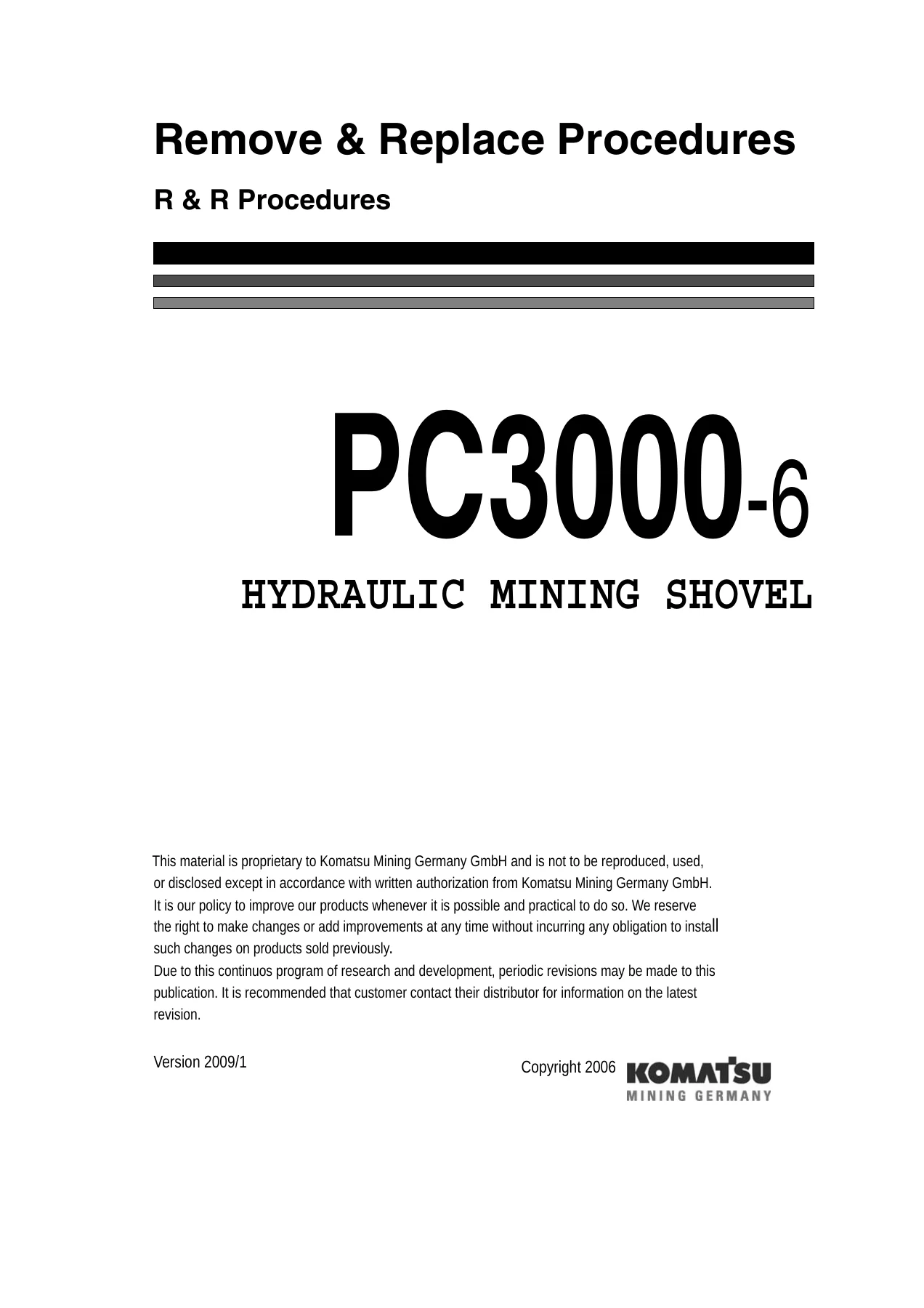
Komatsu PC3000-6 D Hydraulic Mining Shovel Remove & Replace Procedures Manual β€” PDF page 1 preview
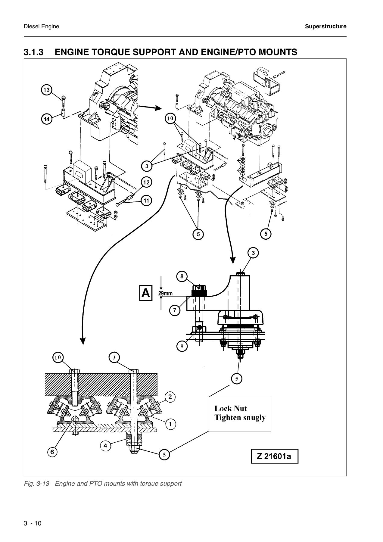
Komatsu PC3000-6 D Hydraulic Mining Shovel Remove & Replace Procedures Manual β€” PDF page 64 preview
Komatsu PC3000-6 D Hydraulic Mining Shovel Remove & Replace Procedures Manual β€” PDF page 124 preview

Reviews

There are no reviews yet.

Be the first to review “Komatsu PC3000-6 D Hydraulic Mining Shovel Remove & Replace Procedures Manual”

What Our Customers Say

β˜…β˜…β˜…β˜…β˜… Live reviews from customers
Loading customer reviews...
0
    0
    Your Cart
    Your cart is emptyReturn to Shop
    πŸ›’
    Recently Purchased
    πŸ•’ verified order