
Komatsu PW140-7 Shop Manual – Complete Repair & Service Guide
Original price was: $49.95.$29.95Current price is: $29.95.
Complete Komatsu PW140-7 shop manual (VEBM410100) covering the wheeled excavator from serial H55051 up with the SAA4D107E-1 engine. A 1106-page PDF workshop reference with repair, testing, and disassembly procedures for the whole machine.
Description
Komatsu PW140-7 Shop Manual – Complete Repair and Service Guide (VEBM410100)
This Komatsu PW140-7 Shop Manual is the complete workshop reference for the PW140-7 wheeled excavator from serial number H55051 and up, equipped with the SAA4D107E-1 engine. Published under document number VEBM410100, this 1106-page manual spans five major sections – General, Structure Function and Maintenance Standard, Testing and Adjusting, Disassembly and Assembly, and Others – giving technicians specification drawings, torque tables, hydraulic circuit diagrams, electrical wiring schematics, diagnostic procedures, and step-by-step component rebuild instructions for the entire machine.
File Details
- Manual type: Komatsu Shop Manual
- Machine model: PW140-7
- Serial number coverage: H55051 and up
- Engine: SAA4D107E-1
- Document number: VEBM410100
- Language: English
- Page count: 1106 pages
- File format: PDF
Chapters Covered in the PW140-7 Shop Manual
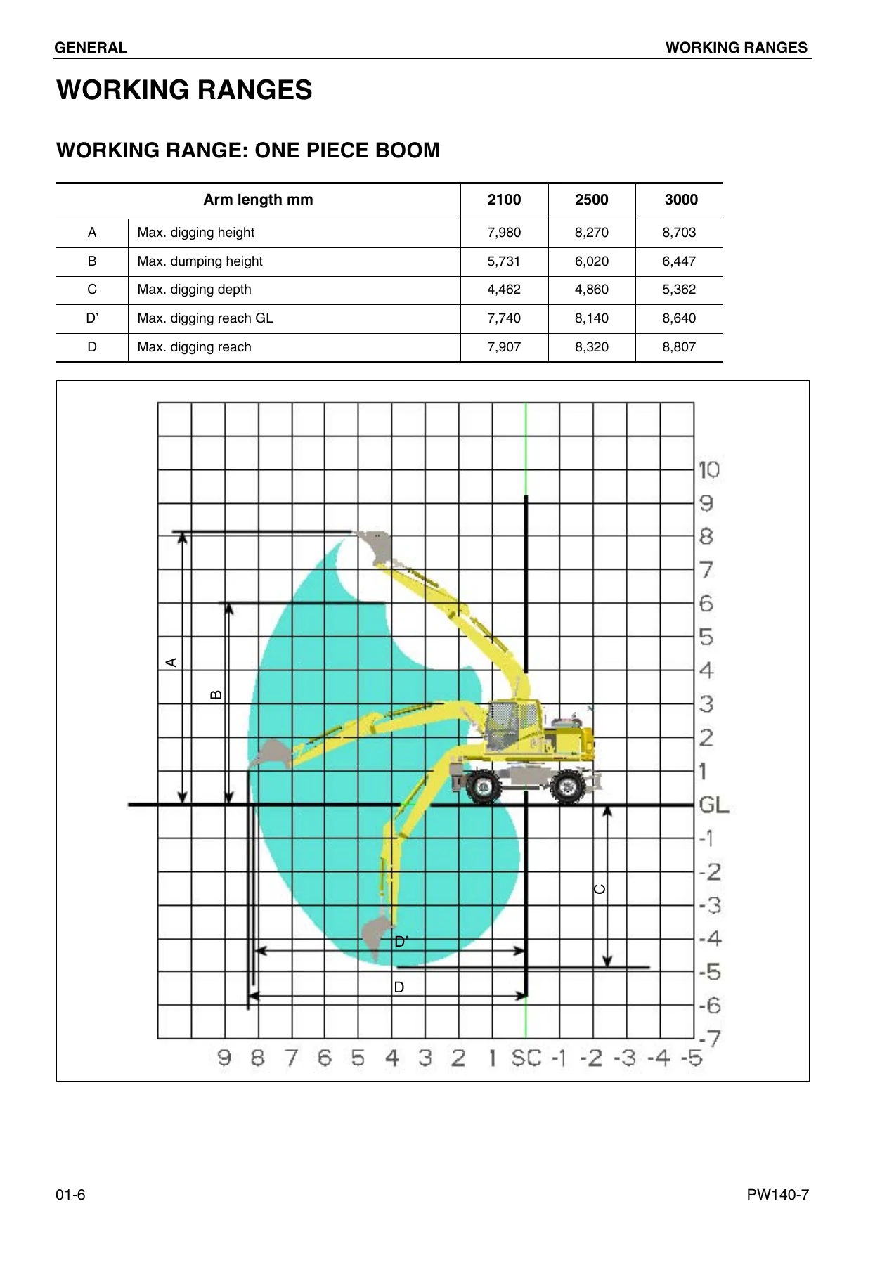
- 01 General – Specification Dimension Drawings (1 Piece Boom, 2 Piece Boom), Working Ranges, Specifications, Weight Table, Fuel, Coolant, and Lubricants
- 10 Structure, Function and Maintenance Standard – Engine Related Parts, Radiator / Oil Cooler / Charge Air Cooler, Power Train, Swing Circle, Swing Machinery, Swing Motor, Undercarriage, Transmission, Travel Motor, Clutch Control Circuit, Axle, Suspension Lock Cylinder, Braking System, Brake/Steer Pump, Priority Valve, Power Brake Valve, Brake Accumulator, Steering System, Steering Column, Orbitrol Valve, Hydraulic Layout Drawing, Hydraulic Circuit Diagram, Hydraulic Tank, Hydraulic Pump, Pilot Pressure Control System, Control Valve, CLSS, Centre Swivel Joint, Travel PPC Pedal, Work Equipment / Swing PPC Valve, Solenoid Valve Manifold, Boom Safety Valve, Hydraulic Cylinder (Boom, Arm, Bucket), Outrigger Cylinder, Dozer Cylinder, Work Equipment, Air Conditioner, Electrical Wiring Diagram, Engine Control System, Electronic Control System, Machine Monitor System, Overload Warning Device, Sensors, Travel System, Steering System, Service Brake and Suspension System
- 20 Testing and Adjusting – Standard Value Tables (Engine and Chassis), Troubleshooting, Troubleshooting When Failure Code is Indicated, Troubleshooting of Electrical System (E-Mode), Error Checking Without Monitor Codes, Troubleshooting of Hydraulic and Mechanical System (H-Mode)
- 30 Disassembly and Assembly – Fuel supply pump, fuel injector, front and rear oil seals, cylinder head, combination cooler, engine and hydraulic pump, engine hood, travel motor, swing motor and swing machinery, front axle, rear axle and transmission, propshaft, wheel, suspension lock cylinder, outrigger, dozer blade, swing circle, revolving frame, centre swivel joint, fuel tank, hydraulic tank, control valve, LS separation valve, pressure compensation valve, main relief valve, LS control EPC valve, PC EPC valve, PPC valve block, hydraulic pump input shaft oil seal, work equipment PPC valve, hydraulic cylinder, monoboom and 2-piece boom work equipment, air conditioner unit, counterweight, operator cab, monitor assembly, pump controller assembly
- 90 Others – Hydraulic Circuit Diagrams (3 sheets), Electrical Circuit Diagrams (multi-monitor)
Between them, these five sections cover the full working life of the machine – from specification checks and pre-delivery inspections through to full teardown, component inspection, rebuild, calibration, and electrical diagnosis. The manual treats the PW140-7 as a complete system, so a hydraulic fault on the boom circuit can be cross-referenced with the electrical control logic, the pressure compensation valves in the control block, the CLSS load-sensing behaviour of the pump, and the PPC pilot circuit – all documented in the same volume.
Structure, Function and Maintenance Standards
The Structure, Function and Maintenance Standard section is the heart of the Komatsu PW140-7 Shop Manual for understanding how the machine is built and how each system should behave. It walks through the engine and its related parts, the combined radiator / oil cooler / charge air cooler, the complete power train from the engine through to the axles, and the swing group – swing circle, swing machinery, swing motor, and the swing lock solenoid. It also details the undercarriage, the transmission and travel motor assemblies, the clutch control circuit, the axles, the suspension lock cylinder, the braking system including the brake/steer pump, priority valve, power brake valve, and brake accumulators, and the full steering system with the steering column and orbitrol valve.
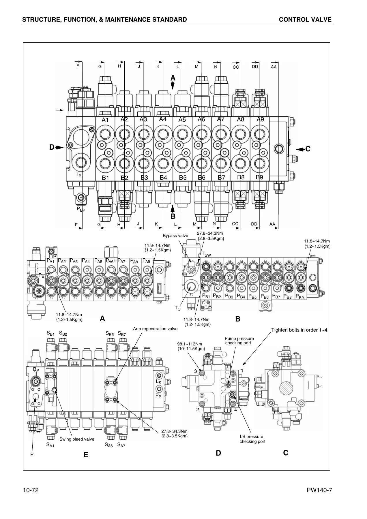
From there it moves through the hydraulic side: hydraulic tank, main hydraulic pump with its PC and LS valves, the pilot pressure control system, the main control valve with pressure compensation and CLSS load-sensing features, the centre swivel joint, travel PPC pedal, work equipment and swing PPC valves, the solenoid valve manifold, the boom safety valve, the hydraulic cylinders for boom, arm and bucket, the outrigger and dozer cylinders, and the full work equipment assembly. Air conditioning, the electrical wiring diagrams, the engine control system, the electronic control system, the machine monitor system, the overload warning device, and the full sensor list round out this section.
Testing, Adjusting and Troubleshooting
The Testing and Adjusting section starts with detailed standard value tables for both the engine and chassis, giving service limits and standard values for every measurable item – engine speed at high idle, low idle and rated speed, valve clearances, compression pressure, blow-by pressure, oil pressure, hydraulic circuit pressures, cylinder drift allowances, control lever strokes, travel speeds, swing times, and more. These tables are the reference point for every diagnosis and are the reason the Komatsu PW140-7 shop manual is used by professional technicians rather than generic repair guides.
From the standard value tables, the section moves into the actual measurement procedures: measuring engine speed, intake air pressure, exhaust gas colour, valve clearance, compression pressure, blow-by pressure, and engine oil pressure; handling and releasing pressure from the common-rail fuel system; measuring fuel pressure, return rate and leakage; bleeding air from the fuel circuit; checking air conditioner belt tension and replacing the fan belt; measuring swing circle bearing clearance; inspecting and adjusting hydraulic oil pressure in the work equipment, swing and travel circuits; control circuit oil pressure; pump PC and LS valve control circuit oil pressure; solenoid valve output pressure; PPC valve output pressure; travel motor relief pressure; propshaft speed; transmission clutch control circuit; locating hydraulic drift; releasing residual pressure; measuring oil leakage; and air bleeding of all major components.
A full troubleshooting chapter follows, split into failure-code troubleshooting, electrical (E-Mode) diagnosis, error checking without monitor codes, and hydraulic and mechanical (H-Mode) diagnosis. Failure codes are listed with symptom, cause, and corrective action. The monitor panel section includes the full special-function menu – monitoring, abnormality history, maintenance history, maintenance mode changes, phone number entry, default settings, adjustments, cylinder cut-out, and no-injection cranking – so the diagnostic capability of the machine can be used to its full extent.
Disassembly and Assembly Procedures
The Disassembly and Assembly section is the most detailed part of the manual. Every major assembly is covered with removal, disassembly, inspection, assembly, and installation procedures in the correct order. Torque values are given at the point of use, coatings and sealants are called out, and each special tool needed is named. The section covers:
- Engine work: fuel supply pump, fuel injectors, front and rear oil seals, cylinder head assembly, combination cooler assembly, engine and hydraulic pump assembly, and engine hood
- Drive train: travel motor, swing motor and swing machinery, front axle, rear axle and transmission, propshaft, and wheel
- Chassis and attachments: suspension lock cylinder, outrigger, and dozer blade
- Upper structure: swing circle, revolving frame, and centre swivel joint
- Tanks and valves: fuel tank, hydraulic tank, control valve, LS separation valve, pressure compensation valve, main relief valve, LS control EPC valve, PC EPC valve, and PPC valve block
- Hydraulics: hydraulic pump input shaft oil seal, work equipment PPC valve, and the hydraulic cylinders for boom, arm and bucket
- Work equipment: monoboom and 2-piece boom assemblies
- Cab and electronics: air conditioner unit, counterweight, operator cab, monitor assembly, and pump controller assembly
Hydraulic and Electrical Circuit Diagrams
The Other section at the end of the manual contains the full hydraulic circuit diagram across three sheets and the electrical circuit diagram across three sheets covering the multi-monitor. These schematics show every component, port, and connection, and they complement the system descriptions in the Structure and Function section to make fault tracing practical rather than guesswork.
Specifications at a Glance
For quick reference, the manual documents the PW140-7 with a 0.55 m3 bucket, operating weight of 14,055 kg, maximum digging force of 93.0 kN (9,483 kg) using the power max function, swing speed of 11.0 rpm, travel speeds of 2.5 km/h in creep, 8.5 km/h in Lo and 35 km/h in Hi, and standard tyre size 10.00-20. Fluid capacities include a 275 litre fuel tank, 166 litre hydraulic tank, 19.1 litre engine oil pan, 16 litre cooling system, 2.5 litre swing machinery case, 10.5 litre front axle, 9.5 litre rear axle, and 4.85 litre transmission.
Who This Komatsu PW140-7 Shop Manual Is For
This manual is written for the working technician, whether in an independent workshop, a fleet maintenance facility, or an owner-operator doing their own servicing. It assumes a professional level of mechanical knowledge but spells out every procedure and specification needed to complete a job correctly. The specification dimension drawings, working range diagrams and weight tables make it equally useful for planning lifts, transport, and site work.
Why the Right Manual Matters
Working on a Komatsu PW140-7 wheeled excavator without the correct specifications is an expensive gamble. Hydraulic pressures, torque values, and clearances are machine-specific; getting them wrong leads to premature failure, oil leaks, poor performance, and in the worst case, damaged components. The Komatsu PW140-7 Shop Manual gives the exact figures for this machine, serial H55051 and up, with the SAA4D107E-1 engine. It replaces guesswork with the reference values Komatsu technicians use.
IMAGES PREVIEW
Instant PDF Delivery
The Komatsu PW140-7 Shop Manual is supplied as a PDF download, ready to open on any computer, tablet, or smartphone. There is no shipping, no waiting, and no risk of a damaged physical book. Once you have it, you can print the pages you need for the job at hand – a pressure table for the shop wall, a wiring diagram for the cab, an assembly sequence for the bench – and keep the full document on file for the next job. Search for a component, jump to a torque value, print a schematic, and get back to work.

Reviews
There are no reviews yet.