★ TRUSTED BY 321,897+ PROFESSIONALS WORLDWIDE
🏒
Trusted Business
Verified & Licensed
πŸ›‘οΈ
Virus Free Files
100% Safe Downloads
πŸ”’
Secure Payment
SSL Protected
⚑
Instant Delivery
Available Immediately
Sale!

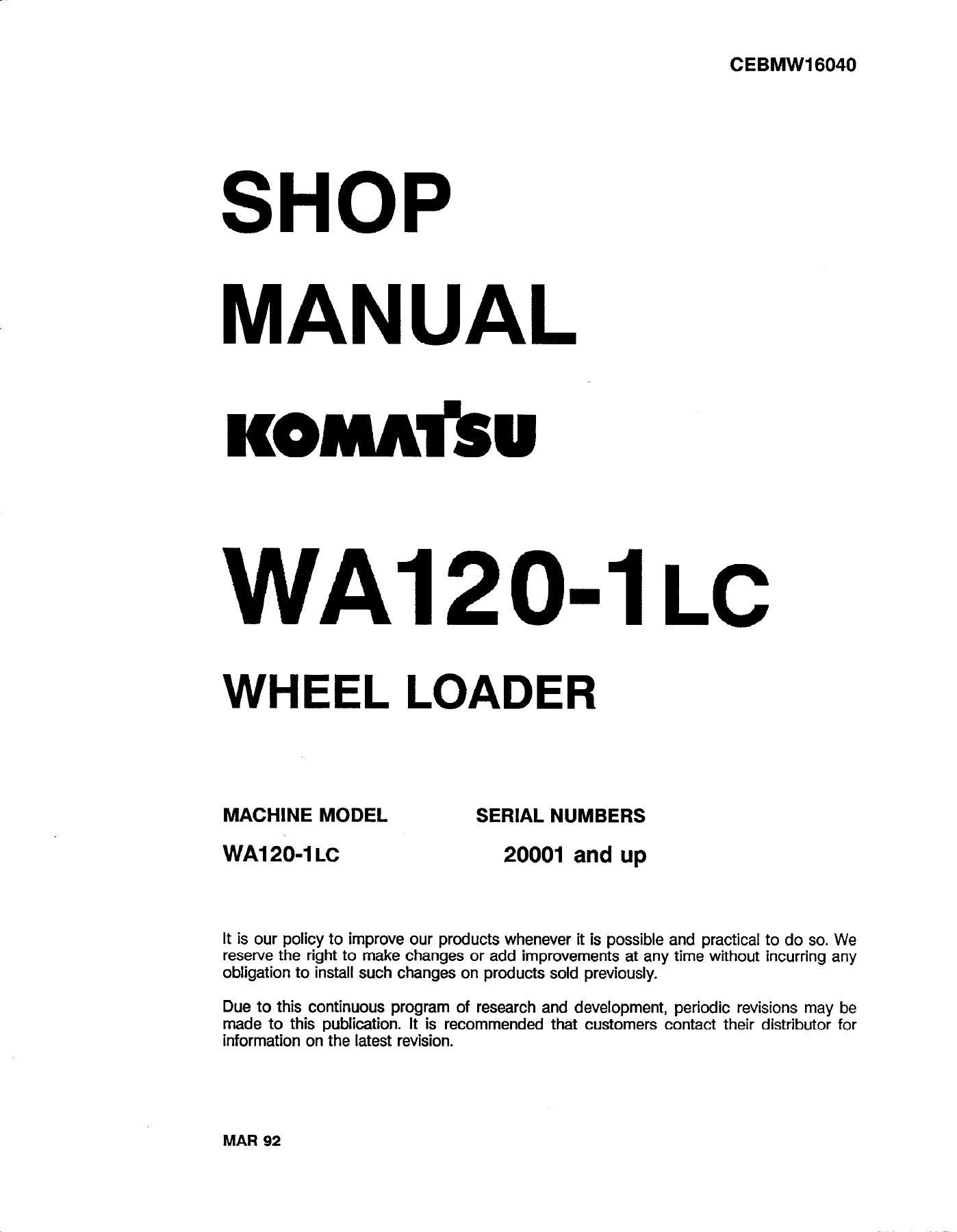
Komatsu WA120-1LC Wheel Loader Shop Manual – CEBMW16040 PDF Repair Guide

Original price was: $39.95.Current price is: $24.95.

Komatsu WA120-1LC Wheel Loader Shop Manual CEBMW16040 in PDF. Complete chassis service coverage for serial numbers 20001 and up: engine, power train, steering, brakes, work equipment and electrical systems with testing, adjusting, disassembly and assembly procedures.

⚑
Instant PDF Download
Available immediately
πŸ’Ύ
Save to Your Device
Download & keep forever
πŸ›‘οΈ
Antivirus Scanned
100% virus-free
🌍
Trusted Worldwide
175,000+ customers

Description

The Komatsu WA120-1LC Wheel Loader Shop Manual is publication CEBMW16040, the chassis service manual covering machines from serial number 20001 and up. It was written for the person doing the work β€” structure and function explanations, testing and adjusting routines, disassembly and assembly sequences, and the maintenance standards used to judge whether a removed part is still serviceable.

This is a full workshop reference rather than a quick-start guide. Every major group on the machine gets its own chapter, and each chapter is split into the same four working sections so you always know where to look: how the component is built and how it behaves, how to test and adjust it, how to take it apart and put it back together, and what the wear limits are.

File Details

  • Manual type: Shop Manual (Chassis)
  • Brand: Komatsu
  • Model: WA120-1LC Wheel Loader
  • Serial number range: WA120-1LC 20001 and up
  • Publication number: CEBMW16040
  • Language: English
  • File format: PDF
  • Page count: 569
  • Companion engine publication: Engine Shop Manual CEBM610SMO (Alternative Repair Manual CEBM610ARO)

Chapters Covered

  • 10 Engine β€” 11 Structure and Function, 12 Testing and Adjusting, 13 Disassembly and Assembly
  • 20 Power Train β€” 21 Structure and Function, 22 Testing and Adjusting, 23 Disassembly and Assembly, 24 Maintenance Standard
  • 40 Steering System β€” 41 Structure and Function, 42 Testing and Adjusting, 43 Disassembly and Assembly, 44 Maintenance Standard
  • 50 Brake System β€” 51 Structure and Function, 52 Testing and Adjusting, 53 Disassembly and Assembly, 54 Maintenance Standard
  • 60 Work Equipment System β€” 61 Structure and Function, 62 Testing and Adjusting, 63 Disassembly and Assembly, 64 Maintenance Standard
  • 80 Electric and Electronic System β€” 81 Structure and Function, 83 Disassembly and Assembly
  • 90 Miscellaneous β€” 97 Gear Pump, 99 Metric Conversions

Read together, these chapters take the WA120-1LC apart and put it back together in a logical order. The engine chapter handles the machine-side work around the power unit β€” cranking motor, alternator, oil cooler, water pump, fuel injectors, turbocharger, cylinder head, radiator, engine removal and installation, and the fuel tank. From there the power train chapter moves through the torque converter charging pump, the torque converter itself, the three-speed-forward three-speed-reverse transmission, the clutch packs, the transmission control valve, the drive shafts and both axles with their differentials and planetary final drives. Steering follows with the fully hydraulic steering valve, priority valve, steering cylinder and the centre hinge pin. Brakes are covered as a wet single-disc system with the master cylinder, calipers and parking brake. The work equipment chapter covers the main control valve, lift and dump cylinders, bucket linkage, hydraulic tank, filter and the hydraulic/steering pump. Electrical coverage includes the cluster gauge, proximity switches, starting and stop circuits, sensors, and the foldout wiring diagram and schematics.

How Each Chapter Is Built

The manual follows a fixed internal pattern, and that pattern is what makes it usable on a real repair rather than just as background reading.

Complete PDF Bookmark Tree

Complete Bookmarks

The complete bookmarks in the β€œKomatsu WA120-1LC Wheel Loader Shop Manual – CEBMW16040 PDF Repair Guide” are as follows:

MAIN MENU
CONTENTSp. 5
10 ENGINEp. 23
11 STRUCTURE AND FUNCTIONp. 23
ENGINE MOUNTINGp. 24
RADIATOR AND OIL COOLERp. 25
FUEL TANK AND PIPINGp. 26
ENGINE CONTROLp. 27
12 TESTING AND ADJUSTINGp. 29
STANDARD VALUE TABLEp. 30
SERVICE TOOL LISTp. 32
SAFETY PRECAUTIONSp. 33
EXHAUST GAS COLORp. 34
ACCELERATOR PEDAL OPERATING FORCE AND ANGLEp. 35
OPERATING FORCEp. 35
OPERATING ANGLEp. 36
13 DISASSEMBLY AND ASSEMBLYp. 39
CRANKING MOTORp. 40
REMOVALp. 40
INSTALLATIONp. 40
ALTERNATORp. 41
REMOVALp. 41
INSTALLATIONp. 41
OIL COOLERp. 42
REMOVALp. 42
INSTALLATIONp. 43
WATER PUMPp. 44
REMOVALp. 44
INSTALLATIONp. 45
FUEL INJECTORSp. 46
REMOVALp. 46
INSTALLATIONp. 48
TURBOCHARGERp. 50
REMOVALp. 50
INSTALLATIONp. 52
CYLINDER HEADp. 54
REMOVALp. 54
INSTALLATIONp. 57
RADIATORp. 60
REMOVALp. 60
INSTALLATIONp. 63
ENGINEp. 67
REMOVALp. 67
INSTALLATIONp. 74
FUEL TANKp. 82
REMOVALp. 82
INSTALLATIONp. 83
20 POWER TRAINp. 85
21 STRUCTURE AND FUNCTIONp. 85
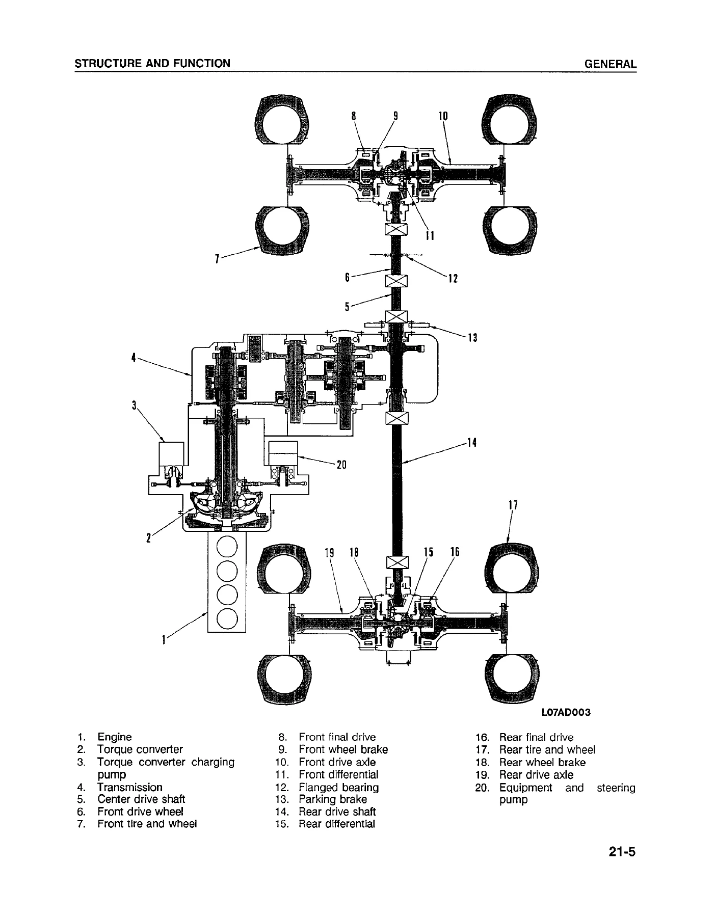
GENERALp. 88
HYDRAULIC CIRCUIT FOR POWER TRAINp. 90
HYDRAULIC CIRCUIT DIAGRAM FOR POWER TRAINp. 91
FORWARD FIRSTp. 92
TORQUE CONVERTER AND TRANSMISSION PIPINGp. 94
TORQUE CONVERTER CHARGING PUMPp. 95
OUTLINEp. 95
SPECIFICATIONSp. 95
TORQUE CONVERTERp. 96
SPECIFICATIONSp. 96
OUTLINEp. 97
FLOW OF MOTIVE FORCEp. 97
FLOW OF OILp. 97
TORQUE CONVERTER OIL FILTERp. 98
OPERATIONp. 98
TORQUE CONVERTER OIL COOLERp. 100
OUTLINEp. 100
TRANSMISSIONp. 101
OUTLINEp. 103
CLUTCH SHAFTSp. 103
FORWARD AND REVERSE CLUTCHESp. 103
FIRST GEAR CLUTCHp. 104
SECOND AND THIRD GEAR CLUTCHp. 104
OPERATION OF CLUTCHp. 105
WHEN ENGAGEDp. 105
WHEN DISENGAGEDp. 105
FORWARD FIRSTp. 106
OPERATIONp. 107
REVERSE FIRSTp. 108
OPERATIONp. 109
TRANSMISSION CONTROL VALVEp. 110
MAIN REGULATOR VALVEp. 112
FUNCTIONp. 112
OPERATIONp. 112
TORQUE CONVERTER OIL OUTLET VALVEp. 113
FUNCTIONp. 113
OPERATIONp. 113
QUICK RETURN VALVE AND ACCUMULATORp. 114
FUNCTIONp. 114
Quick Return Valvep. 114
Accumulatorp. 114
OPERATIONp. 114
When Clutch Is Engagedp. 114
Immediately After Gear Shiftingp. 114
POWER MODULATING FUNCTIONp. 116
FUNCTIONp. 116
CLUTCH CUT-OFF VALVEp. 120
OPERATIONp. 120
DRIVE SHAFTSp. 122
OUTLINEp. 122
AXLESp. 124
FRONTp. 124
REARp. 125
DIFFERENTIALSp. 126
FRONTp. 126
REARp. 127
TORQUE PROPORTIONING DIFFERENTIALp. 128
OUTLINEp. 128
FUNCTIONp. 129
OPERATIONp. 129
FINAL DRIVESp. 130
OUTLINEp. 130
AXLE MOUNTINGp. 132
FRONT AXLEp. 133
REAR AXLEp. 133
TIRES AND WHEELSp. 134
THREE PIECE WHEELp. 134
ONE PIECE WHEELp. 135
SPECIFICATIONSp. 136
22 TESTING AND ADJUSTINGp. 137
STANDARD VALUE TABLEp. 138
SERVICE TOOL LISTp. 140
SAFETY PRECAUTIONSp. 140
ENGINE STALL SPEEDSp. 142
TORQUE CONVERTER AND TRANSMISSION OIL PRESSURESp. 144
TRANSMISSION SHIFT LEVERSp. 146
TRANSMISSION CONTROL VALVE SPOOLSp. 147
TROUBLESHOOTINGp. 149
PRECAUTIONSp. 150
METHOD OF READING TROUBLESHOOTING TABLEp. 152
PREVENTING RECURRENCE OF TROUBLEp. 154
CHECKS BEFORE TROUBLESHOOTINGp. 155
TROUBLESHOOTING TABLEp. 156
TORQUE CONVERTER AND TRANSMISSIONp. 156
1. Machine does not move off.p. 156
2. Machine speed is low, thrust is weak, gradeability falls off.p. 158
3. Large shock when moving off or changing gear.p. 160
4. Large time lag when moving off or changing gear.p. 161
5. Oil temperature in torque converter is high.p. 162
23 DISASSEMBLY AND ASSEMBLYp. 163
TORQUE CONVERTER CHARGING PUMPp. 165
REMOVALp. 165
INSTALLATIONp. 165
TORQUE CONVERTER TRANSMISSIONp. 166
REMOVALp. 166
INSTALLATIONp. 173
TORQUE CONVERTERp. 180
DISASSEMBLYp. 180
ASSEMBLYp. 183
TRANSMISSIONp. 186
DISASSEMBLYp. 186
ASSEMBLYp. 193
FORWARD REVERSE CLUTCH PACKSp. 204
DISASSEMBLYp. 204
ASSEMBLYp. 207
FIRST SPEED CLUTCH PACKp. 212
DISASSEMBLYp. 212
ASSEMBLYp. 214
SECOND AND THIRD SPEED CLUTCH PACKSp. 217
DISASSEMBLYp. 217
ASSEMBLYp. 219
TRANSMISSION CONTROL VALVEp. 224
REMOVALp. 224
INSTALLATIONp. 226
DISASSEMBLYp. 230
ASSEMBLYp. 234
DRIVE SHAFTp. 240
DISASSEMBLYp. 240
ASSEMBLYp. 242
FRONT AXLEp. 244
REMOVALp. 244
INSTALLATIONp. 246
REAR AXLEp. 248
REMOVALp. 248
INSTALLATIONp. 252
DIFFERENTIALp. 257
DISASSEMBLYp. 257
ASSEMBLYp. 261
AXLE HOUSINGp. 271
DISASSEMBLYp. 271
ASSEMBLYp. 277
24 MAINTENANCE STANDARDp. 285
TRANSMISSION AND ENGINE MOUNTp. 286
TORQUE CONVERTER CHARGING PUMPp. 288
TORQUE CONVERTERp. 289
TRANSMISSIONp. 290
TRANSMISSION CLUTCH ASSEMBLYp. 292
FORWARD-REVERSE CLUTCH ASSEMBLYp. 292
1ST CLUTCH ASSEMBLYp. 292
2ND, 3RD CLUTCH ASSEMBLYp. 292
TRANSMISSION CONTROL VALVEp. 294
AXLEp. 296
DIFFERENTIALp. 298
FINAL DRIVEp. 300
DRIVE SHAFTp. 301
AXLE MOUNTp. 302
40 STEERING SYSTEMp. 305
41 STRUCTURE AND FUNCTIONp. 305
GENERALp. 306
HYDRAULIC CIRCUIT FOR STEERINGp. 307
HYDRAULIC CIRCUIT DIAGRAM FOR STEERINGp. 308
STEERING VALVEp. 309
CONNECTION OF HAND PUMP AND SLEEVEp. 315
FUNCTION OF CENTER PINp. 316
PRIORITY VALVEp. 317
STEERING CYLINDERp. 320
CENTER HINGE PINp. 321
42 TESTING AND ADJUSTINGp. 323
STANDARD VALUE TABLEp. 324
SERVICE TOOL LISTp. 324
STEERING WHEEL PLAYp. 325
OPERATING FORCE OF STEERING WHEELp. 326
OPERATING TIME OF STEERING WHEELp. 327
STEERING OIL PRESSUREp. 328
TROUBLESHOOTINGp. 329
TROUBLESHOOTING TABLEp. 330
STEERING CIRCUITp. 330
1. Steering wheel does not turn.p. 330
2. Steering wheel is sluggish.p. 331
3. Steering wheel moves unsteadily or is subjected to large shock.p. 332
4. Machine tends to turn naturally in one particular direction when traveling.p. 332
5. Left and right turning radii are different.p. 332
43 DISASSEMBLY AND ASSEMBLYp. 333
STEERING VALVEp. 334
REMOVALp. 334
INSTALLATIONp. 335
DISASSEMBLYp. 336
ASSEMBLYp. 339
STEERING RELIEF VALVEp. 344
REMOVAL AND DISASSEMBLYp. 344
ASSEMBLY AND INSTALLATIONp. 345
PRIORITY VALVEp. 346
REMOVALp. 346
INSTALLATIONp. 347
STEERING CYLINDERp. 348
REMOVALp. 348
INSTALLATIONp. 348
DISASSEMBLYp. 349
ASSEMBLYp. 351
CENTER HINGE PINp. 354
REMOVALp. 354
INSTALLATIONp. 362
44 MAINTENANCE STANDARDp. 371
STEERING CYLINDER MOUNTp. 372
STEERING CYLINDERp. 373
CENTER HINGE PINp. 374
STEERING COLUMNp. 376
PRIORITY VALVEp. 377
50 BRAKESp. 379
51 STRUCTURE AND FUNCTIONp. 379
GENERALp. 380
BRAKE MASTER CYLINDERp. 381
BRAKEp. 383
PARKING BRAKEp. 385
BRAKE CALIPERp. 386
52 TESTING AND ADJUSTINGp. 387
STANDARD VALUE TABLEp. 388
TOOL LISTp. 389
MEASURING BRAKE PEDALp. 390
BRAKE PEDAL LINKAGEp. 391
BRAKE PERFORMANCEp. 393
BRAKE PISTON LEAKAGEp. 394
BRAKE DISC WEARp. 395
AIR BLEEDING FROM BRAKE CIRCUITp. 396
PARKING BRAKE PERFORMANCEp. 397
PARKING BRAKEp. 398
CHECKINGp. 398
ADJUSTINGp. 399
MEASURING CLEARANCEp. 400
TROUBLESHOOTINGp. 401
TROUBLESHOOTING TABLESp. 402
1. Brake is ineffective or not very effective.p. 402
2. Brake cannot be released or drags.p. 403
53 DISASSEMBLY AND ASSEMBLYp. 405
MASTER CYLINDERp. 406
REMOVALp. 406
INSTALLATIONp. 407
DISASSEMBLYp. 408
ASSEMBLYp. 409
PARKING BRAKEp. 410
REMOVALp. 410
INSTALLATIONp. 412
PARKING BRAKE PADp. 414
REMOVALp. 414
INSTALLATIONp. 415
54 MAINTENANCE STANDARDp. 417
MASTER CYLINDERp. 418
BRAKEp. 419
60 WORK EQUIPMENT SYSTEMp. 421
61 STRUCTURE AND FUNCTIONp. 421
GENERALp. 422
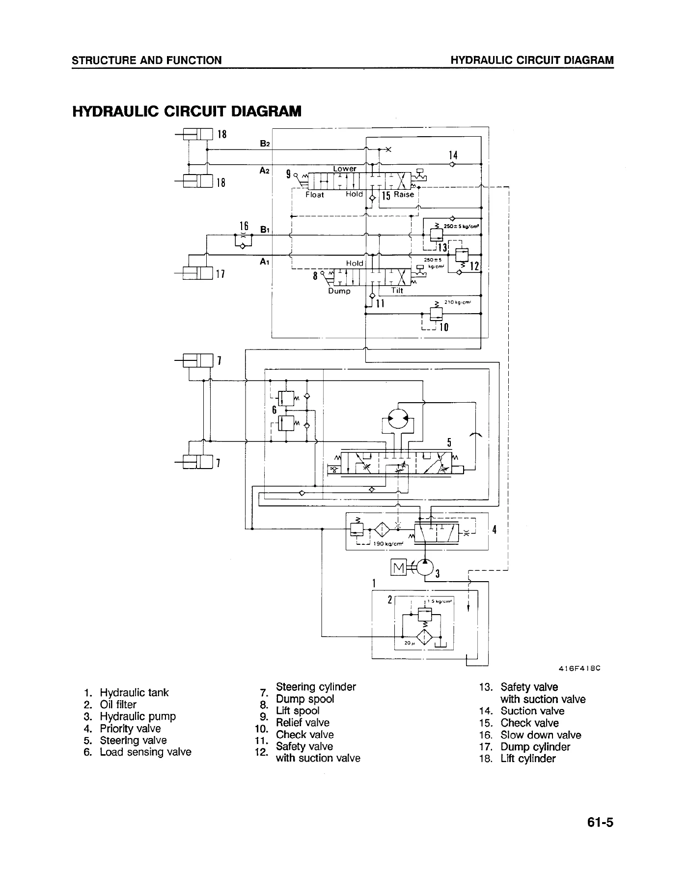
HYDRAULIC CIRCUITp. 424
HYDRAULIC CIRCUIT DIAGRAMp. 425
DUMP AND LIFT CONTROL LEVER LINKAGEp. 426
BUCKET LINKAGEp. 427
BUCKET POSITIONER AND BOOM KICK-OUTp. 429
HYDRAULIC TANKp. 430
OIL FILTER BYPASS VALVEp. 431
BREATHERp. 431
HYDRAULIC AND STEERING PUMPp. 432
MAIN CONTROL VALVEp. 433
RELIEF VALVEp. 435
SAFETY VALVE (WITH SUCTION VALVE)p. 436
SUCTION VALVEp. 437
LIFT AND DUMP SPOOLS AT β€œHOLD POSITION”p. 438
LIFT SPOOL AT β€œRAISE POSITION”p. 439
LIFT SPOOL AT β€œLOWER POSITION”p. 440
DUMP SPOOL AT β€œFLOAT POSITION”p. 441
DUMP SPOOL AT β€œTILT BACK POSITION”p. 442
DUMP SPOOL AT β€œDUMP POSITION”p. 443
HYDRAULIC CYLINDERp. 444
LIFT CYLINDERp. 444
DUMP CYLINDERp. 444
62 TESTING AND ADJUSTINGp. 445
STANDARD VALUE TABLEp. 447
TOOL LISTp. 448
DUMP AND LIFT CONTROL LEVERSp. 449
MEASURING PROCEDUREp. 449
ADJUSTING PROCEDUREp. 450
DUMP AND LIFT CONTROL VALVE SPOOL TRAVELp. 451
MEASURING PROCEDUREp. 451
HYDRAULIC CIRCUIT FLUSHINGp. 452
BEFORE FLUSHINGp. 452
WORK STEPS FOR FLUSHINGp. 453
HYDRAULIC PRESSUREp. 455
MEASURING PROCEDURE (Main relief valve)p. 455
ADJUSTING PROCEDURE (Main relief valve)p. 456
LIFT ARM AND BUCKETp. 457
MEASURING PROCEDUREp. 457
Lifting time of lift armp. 457
Lowering time of lift armp. 457
Dumping time of bucketp. 458
Tilt back time of bucketp. 458
HYDRAULIC DRIFTp. 459
Measuring procedurep. 459
BUCKET POSITIONERp. 460
INSPECTION PROCEDUREp. 460
ADJUSTING PROCEDUREp. 460
BOOM KICK-OUTp. 461
INSPECTION PROCEDUREp. 461
ADJUSTING PROCEDUREp. 461
TROUBLESHOOTINGp. 463
LOADER CIRCUITp. 464
1. Lift arm does not rise.p. 464
2. Lift arm moves slowly or does not have sufficient lifting power.p. 465
3. Lift arm movement becomes slow after it reaches a certain height.p. 466
4. Bucket cannot be held down with lift cylinder.p. 466
5. Lift arm has large hydraulic drift.p. 466
6. Lift arm movement is unsteady during work.p. 466
7. Lift arm descends momentarily when the control lever is shifted from "Hold" to "Raise".p. 466
8. Bucket does not tilt back.p. 467
9. Bucket moves slowly or has insufficient tilt back power.p. 468
10. Bucket movement becomes slow during tilt back.p. 469
11. Bucket cannot be held down by the dump cylinder.p. 469
12. Bucket has large hydraulic drift.p. 469
13. Bucket moves unsteadily when machine travels under load. (Main control valve in "Hold").p. 469
14. Bucket dumps momentarily when control lever is shifted from "Hold" to "Tilt back".p. 469
15. Control levers of lift arm and bucket move stiffly and sluggishly.p. 470
63 DISASSEMBLY AND ASSEMBLYp. 471
HYDRAULIC TANKp. 473
REMOVALp. 473
INSTALLATIONp. 474
HYDRAULIC FILTERp. 475
REMOVALp. 475
INSTALLATIONp. 475
HYDRAULIC-STEERING PUMPp. 476
REMOVALp. 476
INSTALLATlONp. 476
MAIN CONTROL VALVEp. 477
REMOVALp. 477
INSTALLATIONp. 479
DISASSEMBLYp. 483
ASSEMBLYp. 485
DUMP CYLINDERp. 486
REMOVALp. 486
INSTALLATIONp. 488
LIFT CYLINDERp. 489
REMOVALp. 489
INSTALIATIONp. 490
LIFT AND DUMP CYLINDERp. 491
DISASSEMBLYp. 491
ASSEMBLYp. 493
WORK EQUIPMENTp. 496
REMOVALp. 496
INSTALLATIONp. 499
COUNTERWEIGHTp. 502
REMOVALp. 502
INSTALLATIONp. 502
64 STRUCTURE AND FUNCTIONp. 503
MAIN CONTROL VALVEp. 504
PARKING BRAKEp. 506
DUMP CYLINDERp. 507
LIFT CYLINDERp. 508
WORK EQUIPMENTp. 510
BUCKET POSITIONER AND BOOM KICK-OUTp. 512
BUCKETp. 513
HYDRAULIC AND STEERING PUMPp. 514
80 ELECTRIC AND ELECTRONIC SYSTEMp. 515
81 STRUCTURE AND FUNCTIONp. 515
CLUSTER GUAGEp. 516
PROXIMITY SWITCHp. 517
OPERATIONp. 518
ENGINE STARTING CIRCUITp. 519
ENGINE STOP CIRCUITp. 520
ELECTRICAL WIRING DIAGRAMp. 521
ELECTRICAL WIRING SCHEMATICp. 521
SENSORp. 522
BRAKE OIL LEVEL SENSORp. 523
TORQUE CONVERTER OIL TEMPERATURE SENSORp. 523
FUEL GAUGE SENSORp. 524
COOLANT TEMPERATURE SENSORp. 525
ENGINE OIL PRESSURE SENSORp. 525
83 DISASSEMBLY AND ASSEMBLYp. 527
INSTRUMENT PANELp. 528
REMOVALp. 528
INSTALLATIONp. 529
90 MISCELLANEOUSp. 531
97 GEAR PUMPp. 531
GENERALp. 532
PRINCIPLE OF OPERATIONp. 533
MECHANISM FOR DELIVERING OILp. 533
INTERNAL OIL LEAKAGEp. 534
FORCES ACTING ON THE GEARp. 534
"TRAPPING” PHENOMENON OF THE OILp. 535
PRESSURE LOADED TYPE GEAR PUMPp. 536
GENERAL DESCRIPTIONp. 536
STRUCTURE AND OPERATIONp. 537
FIXED SIDE PLATE TYPE GEAR PUMPp. 538
SA SERIESp. 539
STRUCTUREp. 539
FEATURESp. 539
SA-1p. 540
SA-2p. 540
SA-3p. 541
SA-4p. 542
TESTING AND ADJUSTINGp. 543
DISASSEMBLYp. 546
Single pumpp. 546
Tandem pumpp. 549
Triple pumpp. 549
ASSEMBLYp. 550
Single pumpp. 550
Tandem pumpp. 553
Triple pumpp. 554
MAINTENANCE STANDARDp. 555
99 METRIC CONVERSIONSp. 557

Structure and Function explains how a component is assembled and what it does, which doubles as reference material when you are chasing a fault and need to know which internal passage or clutch does what.

Testing and Adjusting gives the checks to make before and after a repair, the adjustments to make once the checks are done, and troubleshooting charts that link a symptom to its likely causes.

Disassembly and Assembly sets out the order in which parts come off and go back on, with the precautions that apply at each step β€” the bolts to leave in place before releasing spring or internal pressure, the parts that must not be pried, the match marks to make before separating housings, the seal rings and O-rings to renew rather than reuse.

Maintenance Standard closes each group with the judgement values used when inspecting disassembled parts, so you are measuring against a published number instead of guessing.

Service Data, Torque Values and Wear Limits

The front of the manual carries the general reference material that gets used on almost every job: standard tightening torques for bolts and nuts by thread diameter, separate tables for split flange bolts and for the nut portion of flared fittings, the coating materials and their applications, the electric wire colour and thickness code used throughout the wiring diagrams, and a weight table for transporting or hoisting individual components such as the engine assembly, transmission with torque converter, axles, lift arm and cylinders.

Lubricants, fuel and coolant selection are covered in the same opening section, including oil viscosity recommendations for normal and arctic operation, the recommended axle oil and substitutes, diesel fuel requirements, and the coolant mixture and water quality standards for the cooling system. Torque converter and transmission oil capacities, coolant capacity and fuel tank capacity are listed alongside.

The maintenance standard chapters then give the measurable limits β€” clearances between shafts, holes and bearings, seal ring groove and width wear, rotating torque figures for shafts, shim thickness selections, back lash values for the differential, and the end play limits for the axle shaft and planetary carrier. Service tool lists appear with each chapter so you know what is needed before starting.

Machine Coverage

Everything in this book is written around one machine: the WA120-1LC wheel loader from serial number 20001 onward. The engine fitted is the KDC Model 410T diesel, and the manual points to the separate engine service manual for internal engine work that falls outside the chassis scope β€” that split is worth knowing before you buy, because this publication covers the machine-side engine work (removal, installation, and the components listed above) rather than a full engine teardown.

Machine-specific detail runs through the whole document. Transmission coverage describes the three forward and three reverse speed arrangement and the hydraulic clutch actuation through the directional and range spools. The torque converter section identifies the TCA30-3A three-element, single stage, single phase unit and explains the oil flow in and out through the cooler. Axle coverage explains the torque proportioning differential and how the odd-tooth pinion changes the reaction between left and right tyres on soft ground. Steering covers the fully hydraulic system with its built-in hand pump function. Electrical coverage explains the starting circuit interlock with the transmission neutral switch, the engine stop circuit through the fuel cut solenoid, and the proximity switches used for the bucket positioner and boom kick-out.

Safety Content

General precautions are given up front: reading the decals on the machine before greasing or repairs, wearing the right protective equipment, blocking the machine and lowering the work equipment before starting, releasing pressure from circuits before opening them, and the handling rules for lifting heavy components. The manual also carries a specific warning about VITON fluorine rubber seals and the hydrofluoric acid they produce when exposed to open flame or extreme temperatures, together with the recommended decontamination procedure.

Each disassembly procedure repeats the relevant warning for that job β€” where to leave bolts in place, where a component is under spring tension, where fingers must not be used to align pin holes, and where a hoist rather than a person should take the weight.

Get the Komatsu WA120-1LC Shop Manual Today

With this Komatsu WA120-1LC Wheel Loader Shop Manual on hand you can diagnose a transmission that will not pull, measure clutch apply pressures at the test ports, adjust the main regulator or torque converter outlet valve, set the accelerator linkage and stopper bolt height, pull and reseal a lift or dump cylinder, work through the steering valve and priority valve, rebuild a differential and set the backlash and tooth contact, bleed the brakes, and torque every fastener to the figure Komatsu published for it.

Having the correct procedures and the correct numbers matters more on a machine like this than on almost anything else. A clutch pack assembled with the wrong clearance, a differential set to the wrong preload, or a hydraulic circuit closed up with a twisted hose will come back β€” and it will cost more the second time. Working from the manufacturer’s own sequence and judgement values is how you avoid that.

IMAGES PREVIEW

Komatsu WA120-1LC Wheel Loader Shop Manual - CEBMW16040 PDF Repair Guide β€” PDF page 1 preview
Komatsu WA120-1LC Wheel Loader Shop Manual - CEBMW16040 PDF Repair Guide β€” PDF page 89 preview
Komatsu WA120-1LC Wheel Loader Shop Manual - CEBMW16040 PDF Repair Guide β€” PDF page 425 preview

The manual is delivered as an instant PDF download. There is nothing to ship and nothing to wait for. Open it on a laptop in the workshop, a tablet on the machine, or a phone beside the bench, and print whichever pages you want to take under the machine with you.

Reviews

There are no reviews yet.

Be the first to review “Komatsu WA120-1LC Wheel Loader Shop Manual – CEBMW16040 PDF Repair Guide”

What Our Customers Say

β˜…β˜…β˜…β˜…β˜… Live reviews from customers
Loading customer reviews...
0
    0
    Your Cart
    Your cart is emptyReturn to Shop
    πŸ›’
    Recently Purchased
    πŸ•’ verified order