
Komatsu WA250-6 Wheel Loader Shop Manual SEN02829-00 – Full PDF Download
Original price was: $44.95.$34.95Current price is: $34.95.
Complete Komatsu WA250-6 Wheel Loader Shop Manual (SEN02829-00) for serial 75001 and up. 352-page PDF covering engine, power train, hydraulics, electrical, brakes and steering with full maintenance standards, diagrams and tightening torque tables. Instant download.
Description
Komatsu WA250-6 Wheel Loader Shop Manual — Complete Service Reference
This is the complete Komatsu WA250-6 wheel loader shop manual, document number SEN02829-00, published in 2007 for machines from serial number 75001 and up. It covers the engine and cooling system, power train, steering, brakes, undercarriage and frame, hydraulic system, work equipment, cab and attachments, and the full electrical system, plus the hydraulic and electrical circuit diagrams. Everything is in English and delivered as a single PDF.
File Details
- Manual type: Shop Manual
- Brand: Komatsu
- Model: WA250-6
- Serial range: 75001 and up
- Document number: SEN02829-00
- Published: 2007 (06-07)
- Language: English
- Page count: 352
- File format: PDF
Chapters Covered
- 00 Index and foreword
- 01 Specification
- 10 Structure, function and maintenance standard
- 90 Diagrams and drawings
01 Specification
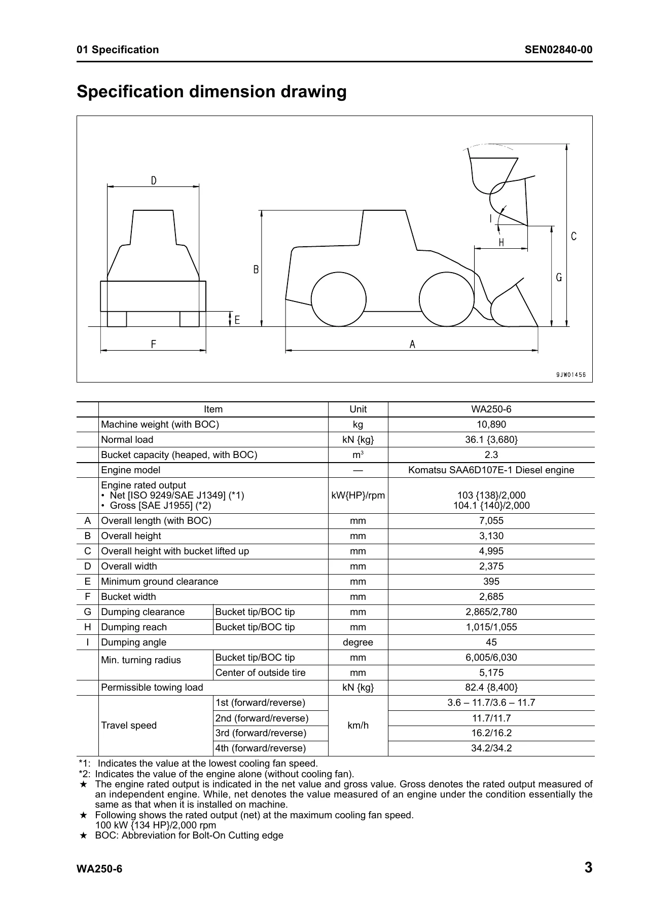
Machine specification dimension drawing, full specification tables, component weight table, and the fuel, coolant and lubricant table with ambient temperature ranges. Use this section to confirm capacities, weights and approved fluids before a service job.
10 Structure, Function and Maintenance Standard
The core technical section, split across ten sub-systems. Each sub-section explains how the system works, gives the maintenance standard values, and lists the tightening torques and clearances you need when inspecting, adjusting or rebuilding components.
Engine and Cooling System, Power Train
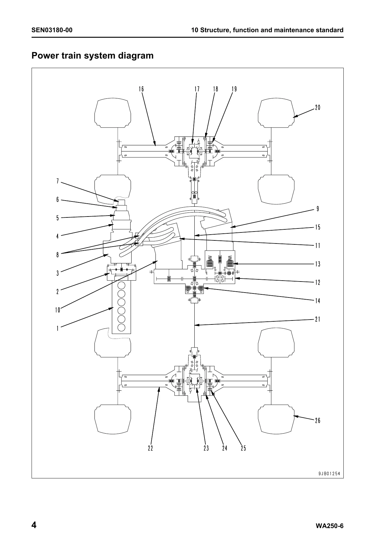
Engine mount and transfer mount, damper with standard size, repair limit and torque, cooling system layout and hydraulic piping diagram, cooling fan motor construction and its valves. Power train schematic, drive shafts, HST hydraulic piping diagram, HST pump A4VG90DA, HST motor 1 A6VM107EP, HST motor 2 A6VM107HA, transfer and transfer clutch, clutch solenoid valve, axle, differential, torque proportioning differential, limited slip differential, and final drive.
Steering, Brake, Undercarriage and Frame
Steering piping diagram, steering column, priority valve, Orbit-roll valve with porting and centering spring explanation, 2-way restrictor valve, cushion valve, steering cylinder, emergency steering piping diagram, emergency steering valve and steering relief valve. Brake piping diagram, charge valve, brake valve, inching valve, accumulator, slack adjuster, front and rear wet multiple disc brakes, parking brake control and parking brake. Axle mount and center hinge pin with clearance, shim and torque tables, plus radial vs bias tire construction.
Hydraulic System and Work Equipment
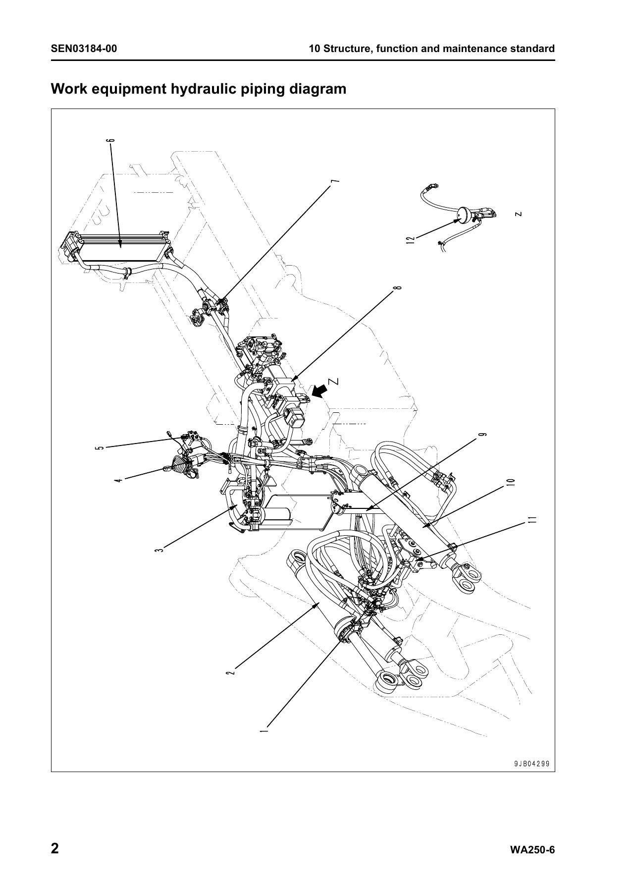
Work equipment hydraulic piping diagram, control lever linkage, hydraulic tank, 4-gear pump covering steering, work equipment, brake and cooling fan and transfer lubrication, work equipment control valve in 2-spool and 3-spool variants, PPC valve in mono-lever and 2-lever configurations, lock valve, PPC accumulator, ECSS valve and ECSS accumulator. Relief valve, suction safety valve and suction valve explanations. Work equipment linkage, bucket, bucket positioner and boom kick-out proximity switch logic, and work equipment cylinder clearances and torque values.
Cab and Electrical Systems
Cab layout, air conditioner piping and refrigerant circuit diagrams, air conditioner unit, blower and intake unit, compressor, condenser, receiver, air conditioner panel with display and switch tables. Electrical Part 1 covers the machine monitor system — displayed items, operating condition tables, lamp, buzzer and priority logic, switches and I/O pinouts. Electrical Part 2 covers the HST controller system including gear shifting, transfer clutch, traction control, S mode, max traction, protection functions, cooling fan control, fan reverse rotation and the economy lamp, plus ECSS, KOMTRAX, engine starting and stopping circuits, preheating, engine output derating, automatic warm-up, parking brake circuit, max traction switch and the full sensor section.
90 Diagrams and Drawings
The hydraulic circuit diagram and the complete electrical circuit diagram, split across nine sheets in the PDF. Print these and pin them to the workshop wall when chasing a wire or tracing an oil path.
What This Komatsu WA250-6 Manual Lets You Do
This is the reference for the jobs that actually come up on a working WA250-6: engine and cooling system diagnosis, HST pump and motor work, transfer clutch service, differential rebuilds, axle and final drive repair, brake valve and slack adjuster service, steering priority valve and Orbit-roll valve troubleshooting, work equipment control valve and PPC valve work, hydraulic cylinder rebuilds, and the electrical side from the machine monitor and HST controller to the starting, stopping, preheating and parking brake circuits.
Because the standard values sit alongside the procedures — tightening torques, clearance limits, spring free lengths, installed loads and repair limits — you can measure, compare and make a proper call instead of replacing parts and hoping. The torque tables cover metric bolts and nuts, split flange bolts, O-ring boss piping joints and plugs, taper and face seal hoses, and the 102, 107 and 114 engine series-specific values.
The electrical section includes connector handling for the slide-lock, pull-lock, push-lock and turn-housing connector types used on Komatsu engines, so you do not damage a harness while chasing a fault. The hydraulic section walks through the suction safety valve, flow control valve, high-pressure cutoff valve and speed-related valve — the parts behind most complaints that the machine will not pull.
IMAGES PREVIEW
Instant PDF Delivery
The Komatsu WA250-6 shop manual is delivered as an instant PDF download after checkout — no shipping, no waiting, no physical binder to lose. Open it on a laptop in the workshop, a tablet at the machine or a phone in the field. Print the pages you need for the job or the full electrical circuit diagram set for the wall. It opens on any device with a PDF reader and can be printed as many times as you need for personal use.
Whether you are a shop technician, a fleet maintenance manager, an independent mechanic or an owner-operator doing your own service, having the complete Komatsu WA250-6 shop manual means every job starts with the correct procedure and the correct specification — the first time.


Reviews
There are no reviews yet.