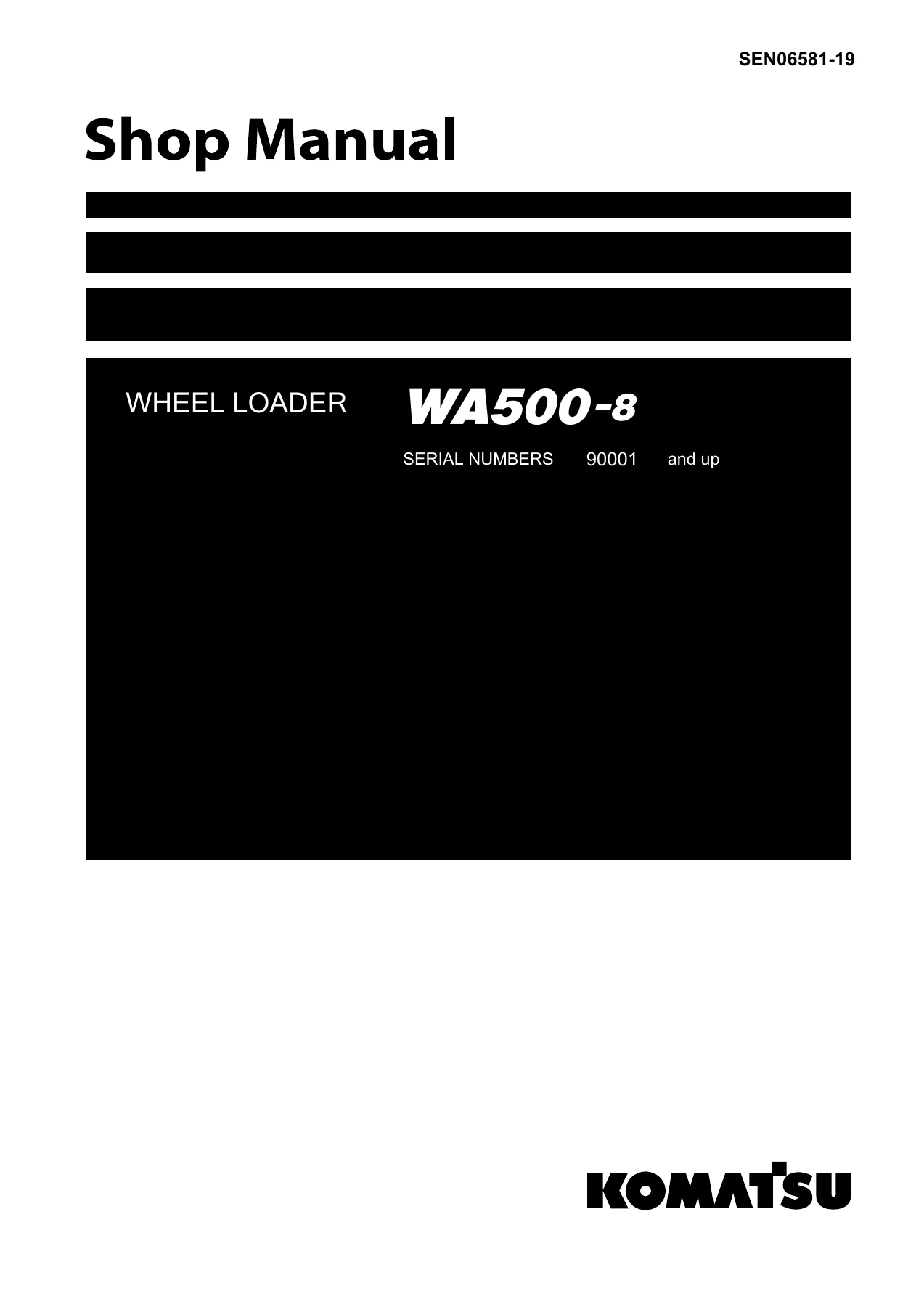
Komatsu WA500-8 Wheel Loader Shop Manual SEN06581-19
$39.95 Original price was: $39.95.$24.95Current price is: $24.95.
Complete Komatsu WA500-8 wheel loader shop manual covering engine, powertrain, hydraulics, steering, brakes, work equipment, electrical systems, troubleshooting, disassembly and assembly, plus full circuit diagrams.
Description
Komatsu WA500-8 Wheel Loader Shop Manual
This is the complete Komatsu WA500-8 wheel loader shop manual, document number SEN06581-19. It is the comprehensive workshop reference used by technicians for servicing, diagnosing, repairing, and rebuilding the WA500-8 wheel loader. The manual covers every major system on the machine, from the SAA6D140E-7 diesel engine and its aftertreatment components through the transmission, axles, hydraulic circuits, steering, brake system, work equipment, and the full electrical architecture. Whether you are performing routine maintenance, tracking down a persistent fault code, or pulling a major component for overhaul, this manual provides the procedures and specifications required to do the job correctly.
The document is organised into clearly separated chapters covering specifications, structure and function, standard value tables, testing and adjusting, troubleshooting, disassembly and assembly, maintenance standards, and circuit diagrams. Each chapter builds on the others, so a technician can move from a symptom to a diagnostic procedure, from a diagnostic result to a repair procedure, and from a repair back to the correct assembly torque and clearance values. This integrated approach is what makes the shop manual essential for anyone maintaining or repairing the WA500-8.
File Details
- Manual type: Shop Manual (Workshop Manual)
- Brand: Komatsu
- Model: WA500-8 Wheel Loader
- Engine: SAA6D140E-7
- Document number: SEN06581-19
- Language: English
- Page count: 4510 pages (original PDF)
- File format: PDF
- Serial number coverage: 90001 and up (with specific variations noted for 90001 to 90960, 90961 and up, 90001 to 91167, and 91168 and up)
Chapters Covered
The manual is divided into major chapters that mirror the way a technician actually works on the machine. The chapter list below gives the top-level structure; each chapter contains detailed sub-sections that are fully searchable within the PDF.
Complete Bookmarks
The complete bookmarks in the βKomatsu WA500-8 Wheel Loader Shop Manual SEN06581-19β are as follows:
+00 Index and Forewordp. 3
+Foreword, Safety, Basic Informationp. 38
+Precautions for DEFp. 53
+Disconnect and Connect Push-Pull Type Couplerp. 70
+01 Specificationsp. 111
+Specificationsp. 119
+Specification Drawingp. 119
+Specificationsp. 121
+Weight Tablep. 126
+10 Structure and Functionp. 131
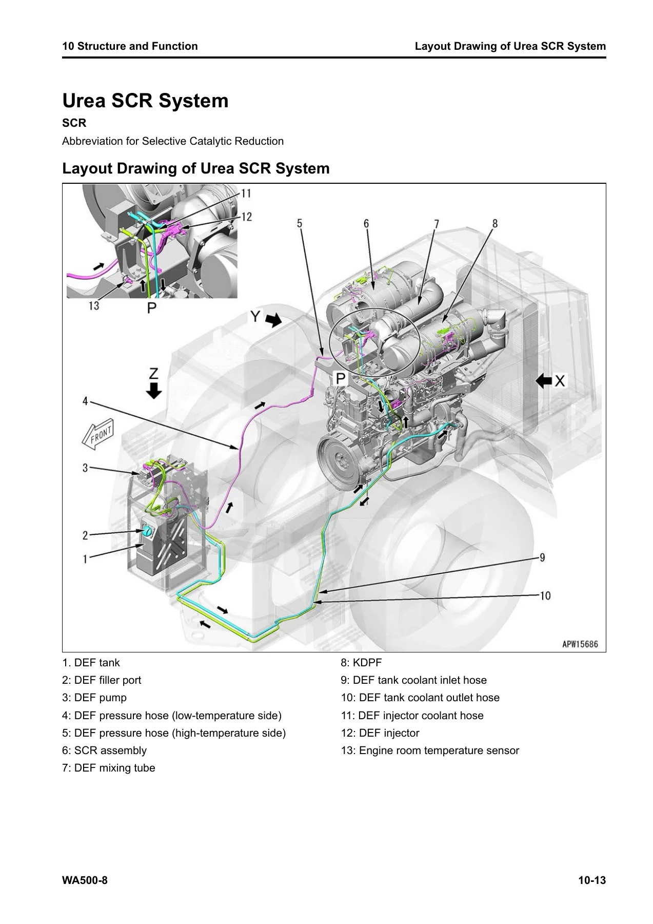
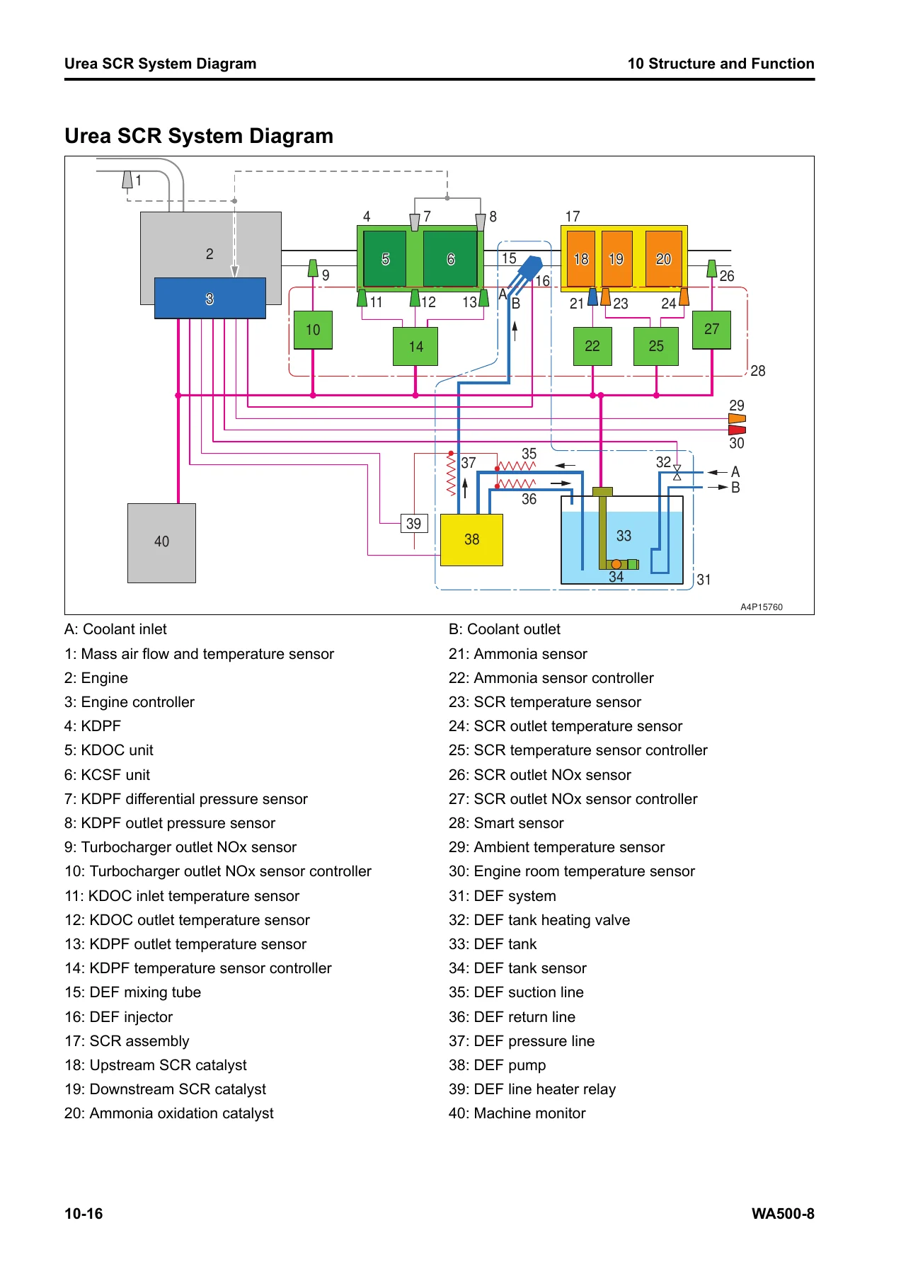
+Urea SCR Systemp. 143
+Function of Urea SCR Systemp. 147
+Component Parts of Urea SCR Systemp. 166
+Boot-up Systemp. 175
+System Operating Lamp Systemp. 184
+Battery Disconnect Switchp. 187
+Preheating Systemp. 190
+Engine Shutdown Secondary Switchp. 192
+Engine Systemp. 194
+Layout Drawing of Engine Systemp. 194
+Engine Control Systemp. 196
+Engine Power Mode Selector Systemp. 203
+Automatic Idle Stop Systemp. 204
+RPM Setp. 205
+Component Parts of Engine Systemp. 209
+Cooling Systemp. 230
+Layout Drawing of Cooling Systemp. 230
+Cooling Fan Control Systemp. 232
+Component Parts of Cooling Systemp. 237
+Control Systemp. 251
+Machine Monitor Systemp. 255
+Rearview Monitor Systemp. 257
+KOMTRAX Systemp. 258
+Load Meter Systemp. 260
+Component Parts of Control Systemp. 267
+Hydraulic Systemp. 324
+CLSSp. 325
+Work Equipment Pump Control Systemp. 329
+Component Parts of Hydraulic Systemp. 330
+Power Train Systemp. 400
+Transmission Control Systemp. 407
+Transmission Gear Shift Control Systemp. 409
+Transmission Protection Functionp. 415
+Component Parts of Power Train Systemp. 422
+Work Equipment Systemp. 486
+Work Equipment Control Systemp. 492
+Work Equipment Neutral Lock Systemp. 497
+Remote Positioner Systemp. 499
+Bucket Positioner and Boom Positionerp. 504
+Auto-Digging Systemp. 505
+ECSSp. 507
+Component Parts of Work Equipment Systemp. 509
+Steering Systemp. 520
+Secondary Steering Systemp. 522
+Joystick Steering Systemp. 523
+AJSSp. 529
+Steering Columnp. 536
+Component Parts of Steering Systemp. 537
+Brake Systemp. 567
+Parking Brake Control Systemp. 570
+Component Parts of Brake Systemp. 572
+Auto-Greasing Systemp. 591
+Auto-Greasing Systemp. 595
+Undercarriage and Framep. 596
+Frame, Axle Mount and Center Hinge Pinp. 596
+Tiresp. 598
+Work Equipmentp. 600
+CAB Related Partsp. 605
+ROPS CABp. 605
+20 Standard Value Tablep. 607
+Standard Value Table for Enginep. 615
+Standard Value Table for Machinep. 618
+30 Testing and Adjustingp. 643
+Related Information on Testing and Adjustingp. 655
+Engine and Cooling Systemp. 668
+Examine Engine Speedp. 668
+Examine Boost Pressurep. 675
+Examine Exhaust Gas Temperaturep. 679
+Examine Exhaust Gas Colorp. 681
+Examine Mass Air Flow and Temperature Sensorp. 684
+Examine and Adjust Valve Clearancep. 686
+Examine Compression Pressurep. 688
+Examine Blowby Pressurep. 691
+Examine Engine Oil Pressurep. 694
+Examine EGR Valve and VGT Oil Pressurep. 696
+Examine Fuel Pressurep. 698
+Examine Fuel Return Rate and Leakagep. 700
+Bleed Air from Fuel Systemp. 704
+Examine Fuel Circuit for Leakagep. 706
+Examine KDPF, SCR and Muffler Stack for Looseness and Damagep. 710
+Examine Installed Condition of Cylinder Heads and Manifoldsp. 711
+Examine Engine Piping for Damage and Loosenessp. 712
+Clean Fuel Doserp. 713
+Write Injector Compensation Value to Engine Controllerp. 716
+Correct Soot Accumulation Correction Value by Ash Influencep. 723
+Examine SCR Related Functionsp. 724
+Clean DEF Tankp. 756
+Clean DEF Pumpp. 760
+Power Trainp. 766
+Examine and Adjust Power Train Oil Pressurep. 766
+Adjust Transmission Input Shaft Speed Sensorp. 784
+Adjust Transmission Output Shaft Speed Sensorp. 786
+Flush Torque Converter and Transmission Hydraulic Circuitp. 788
+Move Disabled Machine Due to Transmission Valve Failurep. 790
+Examine Drive Shaft for Looseness, Backlash, and Damagep. 792
+Steering Systemp. 793
+Examine Steering Wheelp. 793
+Examine and Adjust Steering Circuit Oil Pressurep. 795
+Bleed Air from Steering Cylinder Circuitp. 801
+Examine and Adjust Steering Stop Valvep. 802
+Brake Systemp. 804
+Release Remained Pressure in Brake Accumulator Circuitp. 804
+Examine Wheel Brake Oil Pressurep. 805
+Examine and Adjust Brake Accumulator Charge Pressurep. 807
+Examine Nitrogen Gas Pressure in Brake Accumulator and Charge Gasp. 809
+Bleed Air from Brake Circuitp. 818
+Examine Brake Performancep. 821
+Examine Brake Pedalp. 822
+Examine and Adjust Brake Pedal and Linkagep. 823
+Adjust Left Brake Pedal Operation Switchp. 824
+Examine Pressure Decrease of Wheel Brakep. 825
+Examine Wear of Wheel Brake Discp. 828
+Examine Parking Brake Oil Pressurep. 830
+Examine Parking Brake Performancep. 832
+Release Parking Brake Manuallyp. 833
+Examine Wear Volume of Parking Brake Discp. 836
+Hydraulic Systemp. 838
+Release Remained Pressure from Work Equipment Circuitp. 838
+Examine and Adjust Work Equipment Oil Pressurep. 840
+Examine and Adjust Work Equipment EPC Oil Pressurep. 846
+Bleed Air from Work Equipment Circuitp. 849
+Examine Cooling Fan Speedp. 851
+Examine Cooling Fan Circuit Oil Pressurep. 852
+Bleed Air from Cooling Fan Circuitp. 856
+Examine ECSS Accumulator Nitrogen Gas Pressure and Charge Accumulator with Nitrogen Gasp. 858
+Work Equipmentp. 872
+Examine and Adjust Bucket Potentiometer Leverp. 872
+Examine and Adjust Boom Potentiometer Leverp. 874
+CAB Related Partsp. 875
+Examine Directional Leverp. 875
+Examine Work Equipment Control Leverp. 876
+Examine Multifunction Mono-Leverp. 877
+Examine AJSS Lever (For AJSS Spec)p. 879
+Examine Steering Lock Lever (AJSS Specification)p. 882
+Examine and Adjust AJSS Lever Angle Sensor and AJSS Frame Angle Sensor (AJSS Specifications)p. 883
+Examine and Adjust Steering Stopper Bolt (For AJSS Spec)p. 885
+Adjust Play of Operator Seatp. 887
+Electrical Systemp. 888
+Set and Operate Machine Monitorp. 893
+Adjust Rearview Camera Anglep. 1047
+Set Region of Bluetooth(R) Compatible Radiop. 1048
+Examine Diodesp. 1053
+Auto-Greasing Devicep. 1054
+Bleed the Air in Auto-Greasing Systemp. 1054
+Change Lubrication Time and Lubrication Intervalp. 1057
+Examine and Fill Auto-Greasingp. 1060
+Pm Clinicp. 1062
+Pm Clinic Servicep. 1062
+40 Troubleshootingp. 1075
+Related Information to Troubleshootingp. 1099
+Inspection Procedure Before Troubleshootingp. 1118
+Test in Accordance with Testing Procedurep. 1120
+Troubleshooting by Failure Code (Display of Code)p. 1350
+Failure Code [CA2387]p. 1686
+Troubleshooting of Electrical System (E-Mode)p. 2786
+Troubleshooting for Hydraulic and Mechanical Systems (H Mode)p. 3087
+Troubleshooting of Engine (S-Mode)p. 3178
+Troubleshooting for Auto-Greasing Systemp. 3213
+50 Disassembly and Assemblyp. 3223
+Related Information on Disassembly and Assemblyp. 3236
+Engine and Cooling Systemp. 3277
+Remove and Install Supply Pump Assemblyp. 3277
+Remove and Install Injector Assemblyp. 3287
+Remove and Install Fuel Doser Assemblyp. 3313
+Remove and Install Cylinder Head Assemblyp. 3317
+Remove and Install EGR Valve Assemblyp. 3344
+Remove and Install EGR Cooler Assemblyp. 3346
+Remove and Install Starter Assemblyp. 3354
+Remove and Install Alternator Beltp. 3357
+Remove and Install Radiator Assemblyp. 3359
+Remove and Install Cooling Fan and Fan Motor Assemblyp. 3371
+Remove and Install Hydraulic Oil Cooler Assemblyp. 3377
+Remove and Install Aftercooler Assemblyp. 3389
+Remove and Install Power Train Oil Cooler Assemblyp. 3400
+Remove and Install Engine, Torque Converter, and Transmission Assemblyp. 3405
+Disconnect and Connect Engine, Torque Converter, and Transmission Assemblyp. 3440
+Remove and Install Engine Front Oil Sealp. 3442
+Remove and Install Engine Rear Oil Sealp. 3447
+Remove and Install Engine Hood Assemblyp. 3455
+Remove and Install KDPF Assemblyp. 3463
+Disassemble and Assemble KDPF Assemblyp. 3471
+Remove and Install KDPF and SCR Assemblyp. 3481
+Remove and Install Fuel Tank Assemblyp. 3488
+Remove and Install DEF Tank Assemblyp. 3494
+Remove and Install DEF Tank Sensor Flange Assemblyp. 3510
+Remove and Install DEF Tank Sensorp. 3514
+Remove and Install DEF Tank Strainerp. 3522
+Remove and Install SCR Assemblyp. 3524
+Remove and Install KCCV Assemblyp. 3532
+Remove and Install VGT Assemblyp. 3537
+Remove and Install DEF Mixing Tubep. 3544
+Remove and Install DEF Injectorp. 3551
+Remove and Install DEF Pumpp. 3557
+Remove and Install DEF Hosep. 3563
+Remove and Install Air Cleaner Assemblyp. 3578
+Remove and Install Air Conditioner Compressor Assemblyp. 3584
+Remove and Install Air Conditioner Condenser Assemblyp. 3588
+Power Trainp. 3591
+Disconnect and Connect Torque Converter and Transmission Assemblyp. 3591
+Remove and Install Front Differential Assemblyp. 3603
+Disassemble and Assemble Differential Assembly (Specification with LSD)p. 3607
+Disassemble and Assemble Differential Assembly (Specification Without LSD)p. 3627
+Disassemble and Assemble Torque Converter Assemblyp. 3643
+Disassemble and Assemble Input Transfer Assemblyp. 3663
+Disassemble and Assemble Transmission Assemblyp. 3673
+Disassemble and Assemble Transfer and Parking Brake Assemblyp. 3716
+Remove and Install Front Axle Assemblyp. 3743
+Remove and Install Rear Axle Assemblyp. 3747
+Disassemble and Assemble Final Drive Assembly (Front, Rear)p. 3752
+Steering Systemp. 3761
+Remove and Install Steering Valve Assemblyp. 3761
+Remove and Install Rotary Valve Assembly (For AJSS Spec)p. 3765
+Brake Systemp. 3782
+Disassemble and Assemble Slack Adjuster Assemblyp. 3782
+Disassemble and Assemble Brake Accumulator Charge Valve Assemblyp. 3783
+Remove and Install Brake Assembly (Front, Rear)p. 3784
+Disassemble and Assemble Brake Assembly (Front, Rear)p. 3788
+Undercarriage and Framep. 3797
+Remove and Install Center Hinge Pinp. 3797
+Remove and Install Counterweight Assemblyp. 3813
+Remove and Install Full-Length Fender Assemblyp. 3818
+Hydraulic Systemp. 3821
+Remove and Install Hydraulic Tank Assemblyp. 3821
+Remove and Install Work Equipment Pump Assemblyp. 3833
+Remove and Install Steering Pump and Power Train Pump Assemblyp. 3841
+Remove and Install Diverter Valve Assemblyp. 3850
+Remove and Install Cooling Fan Pump Assemblyp. 3855
+Remove and Install Control Valve Assemblyp. 3860
+Disassemble and Assemble Steering Cylinder Assemblyp. 3866
+Disassemble and Assemble Work Equipment Cylinder Assemblyp. 3871
+Work Equipmentp. 3878
+Remove and Install Work Equipment Assemblyp. 3878
+CAB Related Partsp. 3886
+Remove and Install Operator Cab Assemblyp. 3886
+Remove and Install Operator Cab Glass (Adhered Glass)p. 3906
+Remove and Install Air Conditioner Unit Assemblyp. 3916
+Remove and Install Operator Seat Assemblyp. 3927
+How to Remove and Install Seat Beltp. 3931
+Remove and Install Switch Assembly of AJSS Leverp. 3933
+Electrical Systemp. 3939
+Remove and Install Engine Controller Assemblyp. 3939
+Remove and Install Work Equipment Controller Assemblyp. 3945
+Remove and Install Transmission Controller Assemblyp. 3949
+Remove and Install Monitor Controller Assemblyp. 3951
+Remove and Install Machine Monitor Assemblyp. 3955
+Remove and Install Mass Air Flow and Temperature Sensorp. 3958
+Remove and Install KCCV Crankcase Pressure Sensorp. 3961
+Remove and Install SCR Temperature Sensorp. 3964
+Remove and Install KOMTRAX Terminal Assemblyp. 3968
+Remove and Install Gateway Function Controller Assemblyp. 3970
+Remove and Install Communication Terminalp. 3972
+60 Maintenance Standardp. 3983
+Engine and Cooling Systemp. 3991
+Maintenance Standard for Brake and Cooling Fan Pumpp. 3994
+Power Trainp. 3999
+Maintenance Standard for Drive Shaftp. 3999
+Steering Systemp. 4031
+Maintenance Standard for Steering Pumpp. 4032
+Brake Systemp. 4041
+Undercarriage and Framep. 4051
+Hydraulic Systemp. 4056
+Work Equipmentp. 4071
+80 Appendixp. 4079
+Air Conditioner Systemp. 4089
+Component Parts of Air Conditioner Systemp. 4096
+Air Conditioner Unitp. 4096
+Component Parts of Air Conditioner Unitp. 4098
+Air Conditioner Controllerp. 4101
+Compressorp. 4102
+Condenserp. 4103
+Receiver Drierp. 4104
+Air Conditioner Related Sensorsp. 4105
+System Diagram of Air Conditionerp. 4112
+Input and Output Signals of Air Conditioner Controllerp. 4114
+Examine Temperature Control Functionp. 4125
+Examine Vent (Mode) Changeoverp. 4127
+Examine Fresh/Recirc Air Changeoverp. 4129
+Examine Relayp. 4133
+Connect Service Toolp. 4180
+90 Circuit Diagramsp. 4187
+Hydraulic Circuit Diagramp. 4199
+Electrical Circuit Diagramp. 4213
- 00 Index and Foreword β Abbreviation list, foreword, safety notices, basic information, how to read the shop manual, standard tightening torque tables, conversion tables, and precautions for handling hydraulic, electrical, fuel, intake, and DEF systems. Includes connector disconnection and connection procedures for Deutsch, slide lock, push-pull, and housing-to-rotate connectors.
- 01 Specifications β Specification drawing, machine specifications for the WA500-8, weight table, and the table of fuel, coolant, and lubricants.
- 10 Structure and Function β Detailed explanation of the Urea SCR system, boot-up system, system operating lamp, battery disconnect switch, preheating system, engine shutdown secondary switch, engine control system, engine power mode selector, automatic idle stop, RPM set, cooling system, control system, machine monitor, rearview monitor, KOMTRAX system, load meter system, hydraulic system (CLSS), power train system, transmission control, work equipment system, steering system (including AJSS, joystick steering, and secondary steering), brake system, auto-greasing system, undercarriage and frame, work equipment structure, and ROPS cab.
- 20 Standard Value Table β Standard value tables for the engine and machine, including performance, air intake and exhaust, main body, fuel system, lubrication system, engine speed, SCR related items, pedal and linkage, directional lever, gear speed switch, work equipment control lever, power train oil pressure, travel speed, tires, accumulator, wheel brake, parking brake, steering, work equipment oil pressure, work equipment speed, hydraulic drift, potentiometers, cooling fan, and machine posture and procedures to measure performance.
- 30 Testing and Adjusting β Precautions before work, related information, tools for testing and adjusting, engine and cooling system testing, power train testing and adjustment, steering system testing, brake system testing, hydraulic system testing, work equipment, CAB related parts, electrical system, and auto-greasing device. Includes detailed procedures for examining engine speed, boost pressure, exhaust gas temperature and color, mass air flow sensor, valve clearance, compression pressure, blowby pressure, engine oil pressure, EGR valve and VGT oil pressure, fuel pressure, fuel return rate, and for bleeding air from fuel, steering, brake, work equipment, and cooling fan circuits. Also covers setting and operating the machine monitor, including service mode, diagnostic tests menu, adjustment menu, KOMTRAX settings, and PM clinic check sheets.
- 40 Troubleshooting β Precautions before work, general troubleshooting points, troubleshooting points for the Urea SCR system, sequence of events in troubleshooting, checks before troubleshooting, inspection procedure before troubleshooting, test in accordance with testing procedure, preparation for troubleshooting of the electrical system, procedure for troubleshooting, symptom and troubleshooting numbers, connector list and layout, connector contact connection table, T-branch box and T-branch adapter table, fuse location table, precautions when cleaning and replacing KDPF, preparation for troubleshooting on the machine monitor, procedure to make harness checker on machine monitor LCD unit, prepare short circuit electrical connector, failure code table, and troubleshooting by failure code for a very large number of specific codes. Also includes troubleshooting of the electrical system in E-mode, hydraulic and mechanical systems in H-mode, engine in S-mode, and the auto-greasing system.
- 50 Disassembly and Assembly β Precautions before work, related information, how to read this manual, coating materials list, special tool list and sketches, engine and cooling system, power train, steering system, brake system, undercarriage and frame, hydraulic system, work equipment, CAB related parts, and electrical system. Provides step-by-step removal, installation, disassembly, and assembly procedures with tightening torques, quantities, and weights.
- 60 Maintenance Standard β Maintenance standards for the engine and cooling system, power train, steering system, brake system, undercarriage and frame, hydraulic system, and work equipment. Gives the criteria and remedies for disassembly and assembly decisions.
- 80 Appendix β Air conditioner system, including precautions for refrigerant, component parts, specifications, structure and function of the refrigeration cycle, air conditioner unit, controller, compressor, condenser, receiver drier, sensors, and a full troubleshooting chart with failure codes and procedures.
- 90 Circuit Diagrams β Hydraulic circuit diagrams for steering wheel, joystick steering, and AJSS specifications; power train hydraulic circuit diagram; brake system hydraulic circuit diagram; hydraulic auto-greasing diagram; electrical circuit diagrams for machines with KOMTRAX terminal, machines with gateway function controller (with and without DEF purge relay), floor circuits for steering wheel and joystick steering, and emergency engine stop switch specifications.
This is a workshop manual in the truest sense. It does not stop at describing what the machine is; it goes into exactly how to test it, how to interpret the results, how to take it apart, how to put it back together, and what the correct values are at every stage. The troubleshooting chapter alone is effectively a diagnostic encyclopaedia for the WA500-8, with failure code tables and step-by-step flows that reference the connector layouts, fuse locations, and circuit diagrams included in the same document.
What This Manual Enables You to Do
With the Komatsu WA500-8 shop manual on hand, you can confidently carry out the full range of maintenance and repair work on this machine. That includes engine diagnostics and top-end repairs, fuel system testing, aftertreatment system servicing (KDPF, SCR, DEF), transmission clutch pressure testing and ECMV adjustment, torque converter lockup diagnostics, axle and final drive repair, hydraulic pump and valve testing and overhaul, steering system diagnosis and repair including AJSS and joystick steering variants, brake system bleeding and accumulator charging, work equipment cylinder and linkage service, and the complete electrical system diagnosis using the connector and circuit diagram chapters.
Having the correct procedures and specifications matters more than anything on a machine of this size and complexity. A transmission clutch pressure that is slightly out of tolerance, a hydraulic relief valve that is set incorrectly, a sensor gap that is not adjusted to the specified value, or a torque that is not applied to the correct figure can lead to premature failure, poor performance, or an unsafe machine. The standard value tables and testing and adjusting procedures in this manual give you the actual figures, with the measurement conditions clearly stated, so you are not working from memory or guesswork.
This manual also covers serial-number-specific variations, which is important because Komatsu made running changes across the WA500-8 production range. Procedures, part numbers, and even some system layouts differ between early and later machines, and the manual calls out those differences where they exist. That level of detail is what separates a genuine workshop reference from a generic service guide.
Delivery and Use
IMAGES PREVIEW
The manual is delivered as an instant PDF download. There is no shipping, no waiting for a physical book, and no risk of a printed copy arriving damaged or incomplete. Once downloaded, you can open it on any device β desktop computer, laptop, tablet, or smartphone β and you can print as many pages as you need for use in the workshop. Print the section you are working on, take it to the machine, and keep the full manual on file for future reference. The PDF format keeps every page, diagram, table, and procedure intact, so you get the complete original document in a form that is far easier to search and navigate than a paper copy.
What Our Customers Say
π Related Products
Discover more professional manuals for your equipment

Kobelco SK35SR-6 Hydraulic Excavator Shop Manual - Full PDF Service & Repair Guide

Bobcat A770 All-Wheel Steer Loader Service Manual 7253836 January 2019 PDF

Komatsu PC228US-8 PC228USLC-8 Hydraulic Excavator Shop Manual (SEN05331-05)


Reviews
There are no reviews yet.